OD1650
8
SUBCOURSE NO. OD1650 Edition 8
United States Army Combined Arms Support Command Ordnance Missile and Munitions
Fort Lee, Virginia 23801-1809 6 Credit Hours
GENERAL
The purpose of this subcourse is to increase your knowledge of welding symbols and their use on shop drawings.
Six credit hours are awarded for successful completion of this subcourse
Lesson 1: WELDING SYMBOLS
TASK 1: Interpret welding symbols and describe the use of welding symbols on shop drawings.
TABLE OF CONTENTS
Section Page
TITLE... i
TABLE OF CONTENTS... ii
Lesson 1: WELDING SYMBOLS... 1
Task 1: Interpret welding symbols and describe the use of welding symbols on shop drawings... 1
Practical Exercise 1... 41
Answers to Practical Exercise 1... 43
REFERENCES... 45
*** IMPORTANT NOTICE ***
THE PASSING SCORE FOR ALL ACCP MATERIAL IS NOW 70%.
LESSON 1 WELDING SYMBOLS
TASK 1. Interpret welding symbols and describe the use of welding symbols on shop drawings.
CONDITIONS
Within a self-study environment and given the subcourse text, without assistance.
STANDARDS Within five hours
REFERENCES
No supplementary references are needed for this task.
1. Introduction
Welding is one of the most important functions performed within a metalworking shop. Many broken parts may be welded and put back into service, saving the expense of fabricating or purchasing a new piece of equipment, and downtime is reduced. This task will describe the welding process, to include the interpretation and identification of welding symbols used in shop drawings.
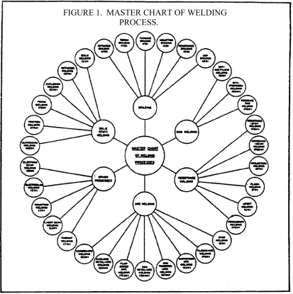
2. Welding Process
FIGURE 1. MASTER CHART OF WELDING PROCESS.
Brazing, the only welding process in which the melting of the base metal is not necessary for coalescence, is similar to soldering, except that higher temperatures are used. The term soldering is used to describe a joining process using nonferrous filler alloys melting below 800°F (427°C). Soldering is not considered a welding process. Brazing is a welding process using nonferrous filler alloys that have a melting point above 800°F (427°C) but below that of the base metal. c. Intimacy of Contact. The second basic requirement for coalescence, intimacy of contact, may be divided into two groups: pressure processes and nonpressure processes. In pressure processes, intimacy of contact is achieved by applying pressure while the contact surfaces are at a high enough temperature to allow plastic flow of the metal. In nonpressure processes, a space remains between the surfaces to be joined. This space is then filled, either progressively or all at once, with molten metal. The molten metal may be obtained from a filler metal (welding rod or electrode) by melting the surfaces to be joined, or by combining a filler metal and melted base metal.
All nonpressure processes involve fusion, and they are often referred to as fusion processes. However, this term is somewhat misleading since some pressure processes also involve fusion. The various welding processes differ not only in the way coalescence is achieved, but also in their ability to produce a satisfactory joint in a given kind of metal under the conditions in which the weld must be made. Many factors influence the selection of a welding process for a particular application. These factors include the relative cost, the amount of welding required, the location and position of welds, the service conditions the welded structure must withstand, and the qualifications of the person who does the welding. Probably the most important single factor, however, is the weldability of the metal.
welds with properties that are equal to or better than the properties of the base material. For example, mild steel can be welded by most welding processes, but the welds produced are not equally satisfactory, and one method may be more complicated or more expensive than another. While it is possible to weld mild steel through the use of a variety of welding processes, some metals such as aluminum and its alloys can be welded satisfactorily through only a few welding processes. Mild steel does not require elaborate preparations, fluxes, and special techniques because its characteristics are such that the welding operation can be easily performed. Other metals require special preparatory steps, complex welding sequences, skillful use of a specific welding technique, and extensive heat treatments after welding.
Many factors influence the weldability of a metal. Some important ones that must be taken into account and, so far as possible, controlled are:
(1) the chemical composition of the metals involved (that is, the kind and percentage of elements present) and the effect of radical temperature changes on the various elements;
(2) the expansion and contraction characteristics of the base metals; (3) the filler metal (welding rod or electrode);
(4) the joint design; and (5) the welding procedure.
When the percentage of carbon is less than 0.25 percent, its effect in producing hardness is slight. But when the carbon content exceeds 0.25 percent, or when such elements as manganese, vanadium, chromium, molybdenum, or titanium are present, together with a carbon percentage of less than 0.25 percent, the weldability of the steel is decreased. Special steps should be taken to control preheat, interpass temperature, postheat, and welding sequence. Otherwise a satisfactory weld is likely to crack and to have reduced toughness and less strength than is required. For this reason, tool steels and certain alloys like carbon-molybdenum steel are less weldable than many other steels.
Steels contain certain impurities such as sulfur, phosphorus, hydrogen, nitrogen, and oxygen. If present in large enough quantities, these impurities may decrease weldability. For example, a steel to which about 0.10 percent sulfur has been added to improve machineability is difficult to weld because the weld has a tendency to crack. An excessive amount of phosphorus decreases the ductility of the steel and thus decreases the weldability of the metal. The presence of hydrogen in a steel, filler material, or flux may lead to cracks in the welds.
Stainless steels, high-chromium steels, and other special steels are less weldable than plain low-carbon steels. The elements that give these special steels their desirable properties for specific applications also have the effect of decreasing the weldability of the metals. To make these special steels weldable, the welding procedures, the filler metal, the fluxes, the preheat and postheat temperatures, and the welding sequence must be carefully selected. This is also true for many nickel, copper, and aluminum alloys.
The weldability of a metal is also affected by its thermal conductivity. In general, metals with high thermal conductivity are difficult to weld because they transfer the heat away from the weld so rapidly that the required temperature cannot be maintained at the joint.
Changes in temperature cause a metal to expand or contract and this also affects weldability. When metals expand and contract at different rates, the internal stresses set up by these changes can cause the joint to crack immediately, or to crack later under load.
Even when the weld joins identical metals, or metals having approximately the same coefficient of expansion, the expansion and contraction may not be uniform throughout all parts of the metal. These differences lead to internal stresses, distortion, and warping. Metal parts must be free to move or a special weld sequence must be used. When heat is applied or withdrawn, expansion and contraction set up high stresses, which may cause trouble in the weld itself or in the adjacent base metal. In thin materials, uneven expansion and contraction may cause the metal to warp. In heavy material, the stresses set up may exceed the ultimate strength of the metal and cause cracking to occur in the weld, or in the metal next to the weld which is called the heat-affected zone.
Even if the ultimate strength of the material is not exceeded by the stresses developed during welding, the combination of welding stresses plus the stresses developed when the material is placed in service may-be enough to cause failure of-the weld. It is for this reason that many materials are stress-relieved after welding.
In some processes, the flux selected for use with a welding rod has important effects on weldability. Also, the electrode covering influences the weld obtained in certain steels. Molten steels have a tendency to absorb hydrogen from the surrounding atmosphere and to expel it when they solidify. Some types of electrode coverings send a lot of hydrogen into the atmosphere surrounding the arc and the molten puddle. This hydrogen is enough to cause microscopic cracks in the heat-affected zone of some steels. To eliminate this problem, low-hydrogen electrodes have been developed to weld the newer high-tensile steels.
Joint design also influences the weldability of a metal. Several factors must be considered when selecting a joint design. They include the welding process, the thickness of the material to be welded, and the purpose the joint is to serve.
Thin sheets of metal can be butted together without special preparation other than cleaning; but heavy plates must be beveled or grooved to make a satisfactory joint. Again, the design used is related to the purpose; that is, the way the load or stress is applied, the erosive or corrosive conditions it must resist, and the joint efficiency. The term "joint efficiency" is used to indicate the strength of a welded joint as compared with the strength of the unwelded base metal.
Each of the welding processes has a technique or procedure peculiar to that process. Often the technique varies with the kind or size of the filler metal used, or the kind of weld being made. The incorrect use of a technique, or the use of the wrong technique, may lead to defects that make the joint unsatisfactory.
3. Weld and Welding Symbols
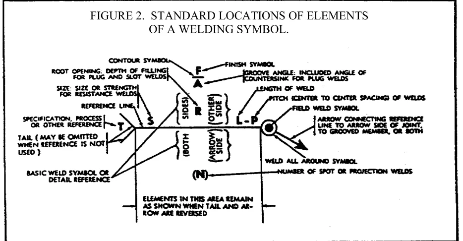
[image:14.612.75.542.255.498.2]a. General. Welding symbols provide the means for placing complete and concise welding information on drawings. The reference line of the welding symbol (figure 2) is used to designate the type of weld to be made, its location, dimensions, extent, contour, and other supplementary information. When necessary, a tail is attached to the reference line which provides specific notations. When such notations are not required the tail is omitted.
FIGURE 2. STANDARD LOCATIONS OF ELEMENTS OF A WELDING SYMBOL.
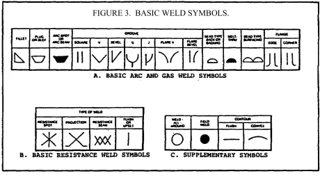
FIGURE 3. BASIC WELD SYMBOLS.
c. Basic Weld Symbols.
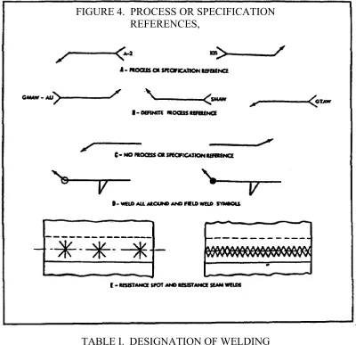
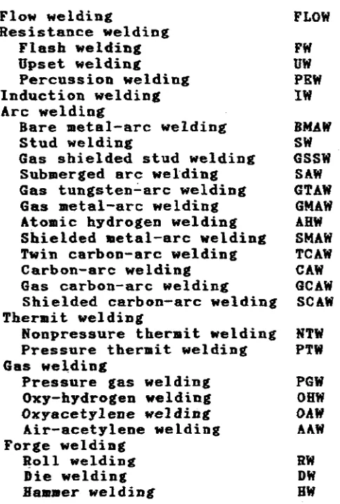
(1) General. Weld symbols are used to indicate the following welding processes used in metal joining operations; whether the weld is localized or "all around"; shop or field welds; and the contour of welds. These basic weld symbols are summarized in paragraphs (2) through (5) below and are illustrated in figure 4 on the following page.
FIGURE 4. PROCESS OR SPECIFICATION REFERENCES,
TABLE I. DESIGNATION OF WELDING
PROCESSES BY LETTERS* (CONTINUED)
*The following suffixes may be used to indicate the method of applying the above processes:
Automatic welding AU
Machine welding ME
Manual welding MA
Semi-automatic welding SA
NOTE
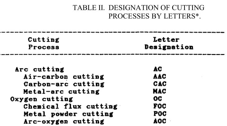
TABLE II. DESIGNATION OF CUTTING PROCESSES BY LETTERS*.
*The following suffixes may be used to indicate the methods of applying the above processes:
Automatic cutting AU
Machine cutting ME
Manual cutting MA
Semi-automatic cutting SA
(5) Supplementary Symbols. These symbols are used in many welding processes and will be used as shown in figure 3, view C, on page 9.
d. Location Significance of Arrow.
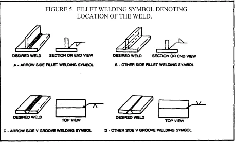
(1) In fillet, groove, flange, and flash or upset welding symbols, the arrow will connect the welding symbol reference line to one side of the joint, and this side will be considered the arrow side of the joint (figure 5, view A, on the following page). The side opposite the arrow side of the joint is considered the other side of the joint (figure 5, view B).
FIGURE 5. FILLET WELDING SYMBOL DENOTING LOCATION OF THE WELD.
The other member of the joint will be considered the other side member (figure 6, views A and B, on the following page).
(3) When a joint is depicted by a single line on the drawing and the arrow of a welding symbol is directed to this line, the arrow side of the joint will be considered as the near side of the joint, in accordance with the usual conventions of drafting (figure 5, views C and D).
(4) When a joint is depicted as an area parallel to the plane of projection in a drawing and the arrow of a welding symbol is directed to that area, the arrow side member of the joint will be considered as the near member of the joint, in accordance with the usual conventions of drafting (figure 6, views A and B).
e. Location of the Weld With Respect to the Joint.
FIGURE 6. PLUG AND SLOT WELDING SYMBOLS INDICATING LOCATION AND
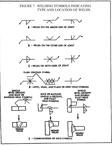
FIGURE 7. WELDING SYMBOLS INDICATING TYPE AND LOCATION OF WELDS.
(3) Welds on both sides of the joint will be shown by placing weld symbols on both sides of the reference line, toward and away from the viewer (figure 7, view C, on the previous page).
(4) Resistance spot, resistance seam, flash .and upset weld symbols have no arrow side or other side significance in themselves, although supplementary symbols used in conjunction with these symbols may have such significance. For example: the flush contour symbol (refer to figure 3, view C, on page 9) is used in conjunction with the spot and seam symbols (figure 7, view D) to show that the exposed surface of one member of the joint is to be flush. Resistance spot, resistance seam, flash and upset weld symbols will be centered on the reference line (figure 7, view D).
f. References and General Notes.
(1) Symbols may be used without specification, process or other references in the following circumstances:
(a) A note such as the following appears on the drawing: "Unless otherwise designated, all welds are to be made in accordance with Specification No ..."
(b) The welding procedure to be used is prescribed elsewhere.
(2) General notes, such as the following, may be placed on a drawing to provide detailed information pertaining to the predominating welds, and this information need not be repeated on the symbols:
(a) "Unless otherwise indicated, all fillet welds are 5/16 inch size."
(b) "Unless otherwise indicated, root openings for all groove welds are 3/16 inch." g. Weld-All-Around and Field Weld Symbols.
(2) Field welds are welds not made in a shop or at the place of initial construction and will be indicated by means of the field weld symbol (figure 4, view D, on page 10).
h. Extent of Welding Denoted by Symbols.
(1) Symbols apply between abrupt changes in the direction of the welding, or to the extent of hatching or dimension lines, except when the weld-all-around symbol is used.
(2) The welding on hidden joints may be covered when the welding is the same as that of the visible joint. The drawing will indicate the presence of hidden members. If the welding on the hidden joint is different from that of the visible joint, specific information for the welding of both will be given.
i. Location of Weld Symbols.
(1) Weld symbols, except resistance spot and resistance seam, will be shown only on the welding symbol reference line and not on the lines of the drawing.
(2) Resistance spot and resistance seam weld symbols may be placed directly at the locations of the desired welds (refer to figure 4, view E).
j. Use of Inch, Degree and Pound Marks. Inch, degree, and pound marks may or may not be used on welding symbols, as desired, except that inch marks will be used for indicating the diameter of arc spot, resistance spot and circular projection welds, and the width of arc seam and resistance seam welds, when such welds are specified by decimal dimensions.
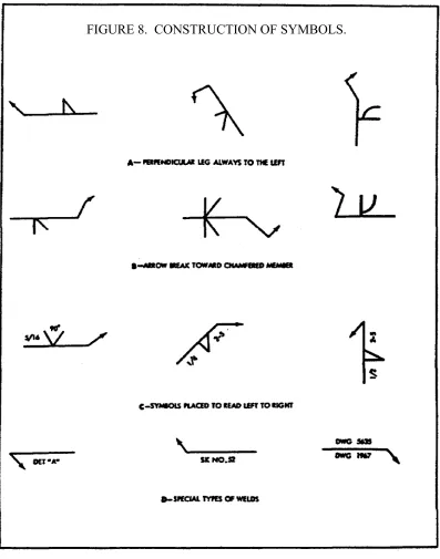
k. Construction of Symbols.
(1) Fillet, bevel and J groove, flare bevel groove, and corner flange symbols will be shown with the perpendicular leg always to the left (figure 8, view A, on the following page).
(3) Information on welding symbols will be placed to read from left to right along the reference line, in accordance with the usual conventions of drafting (figure 8, view C).
(4) For joints having more than one weld, a symbol will be shown for each weld (refer to figure 7, view E, on page 15).
(5) When the basic weld symbols are inadequate to indicate the desired weld, the weld will be shown by a cross section, detail or other data, with a reference on the welding symbol, observing the usual location significance (figure 8, view D, on the previous page).
l. Fillet Welds.
(1) Dimensions of fillet welds will be shown on the same side of the reference line as the weld symbol (figure 9, view A, on the following page).
(2) When fillet welds are indicated on both sides of a joint and no general note governing the dimensions of the welds appears on the drawing, the dimensions will be indicated as follows:
(a) When both welds have the same dimensions, one or both may be dimensioned (figure 8, views B and C).
(b) When the welds differ in dimensions, both will be dimensioned (figure 9, view D).
(3) When fillet welds are indicated on both sides of a joint and a general note governing the dimensions of the welds appears on the drawing, neither weld need be dimensioned. But if the dimensions of one or both welds differ from the dimensions given in the general note, both welds shall be dimensioned (figure 9, views C or D).
m. Size of Fillet Welds.
(1) The size of a fillet weld will be shown to the left of the weld symbol (figure 9, view A).
FIGURE 9. FILLET WELDS.
(2) When fillet welding extends for the full distance between abrupt changes in the direction of the welding, no length dimension need be shown on the welding symbol.
(3) Specific lengths of fillet welding may be indicated by symbols in conjunction with dimension lines (figure 9, view I, on the previous page).
o. Extent of Fillet Welding.
(1) When it is desired to show the extent of fillet welding graphically, one type of hatching, with or without definite lines, shall be used.
(2) Fillet welding extending beyond abrupt changes in direction of the welding will be indicated by means of additional arrows pointing to each section of the joint to be welded (figure 9, view H), except when the weld-all-around symbol is used.
p. Dimensioning of Intermittent Fillet Welding.
(1) The pitch (center-to-center spacing) of intermittent fillet welding will be shown as the distance between centers of increments on one side of the joint.
(2) The pitch of intermittent fillet welding will be shown to the right of the length dimension (figure 9, view A).
(3) Chain intermittent fillet welding will be shown in figure 9, view F.
(4) Staggered intermittent fillet welding will be shown in figure 9, view G. q. Termination of Intermittent Fillet Welding.
(1) When intermittent fillet welding is used by itself, the symbol indicates that increments will be located at the ends of the dimensional length.
be used for intermittent and continuous fillet welding when the two are used in combination (figure 9, view I, on page 20).
r. Surface Contour of Fillet Welds.
(1) Fillet welds that are to be welded approximately flat faced, without recourse to any method of finishing, will be shown by adding the flush contour symbol to the weld symbol, observing the usual location significance (figure 9, view J).
(2) Fillet welds that are to be made flat faced by mechanical means will be shown by adding both the flush contour symbol and the user's standard finish symbol, observing the usual location significance (figure 9, view K).
(3) Fillet welds that are to be mechanically finished to a convex contour will be shown by adding both the convex contour symbol and the user's standard finish symbol to the weld symbol, observing the usual location significance (figure 9, view D).
NOTE
The finish symbols referred to in (2) and (3) above indicate the method of finishing ("C" = chipping; "G" = grinding; "H" = hammering; "M" = machining) and not the degree of finish.
s. Plug and Slot Welding Symbols.
(1) General. Neither the plug weld symbol nor the slot weld symbol will be used to designate fillet welds in holes.
(3) Plug Weld Dimensions. Dimensions of plug welds will be shown on the same side of the reference line as the weld symbol. The size of a weld will be shown to the left of the weld symbol. Included angle of countersink of plug welds shall be the user's standard, unless otherwise indicated. Included angle of countersink, when not the user's standard, will be shown either above or below the weld symbol (refer to figure 6, views C and E, on page 14). The pitch (center-to-center spacing) of plug welds will be shown to the right of the weld symbol.
(4) Depth of Filling of Plug and Slot Welds. Depth of filling of plug and slot welds will be complete unless otherwise indicated. When the depth is less than complete the depth of the filling will be shown in inches inside the weld symbol (refer to figure 6, view D).
(5) Details of Slot Welds. Length, width, spacing, included angle of countersink, orientation and location of slot welds cannot be shown on the welding symbols. These data will be shown on the drawing, or by a detail with a reference to it on the welding symbol, observing the usual location significance (refer to figure 6, view F).
(6) Surface Contour of Plug and Slot Welds. The surface contour (figure 6, view G) shall be indicated in the same manner as that for fillet welds.
t. Arc Spot and Arc Seam Welds.
(1) General. Dimensions for arc spot and arc seam welds will be shown on the same side of the reference line is the weld symbol.
(2) Size of Arc Spot and Arc Seam Welds.
(a) These welds may be dimensioned by either size or strength.
FIGURE 10. ARC SPOT AND ARC SEAM WELDS.
(c) The strength of arc spot welds will be designated as the minimum acceptable shear strength in pounds per spot. In arc seam welds strength is designated in pounds per linear inch. Strength is shown to the left of the weld symbol (figure 10, view B).
(3) Spacing Arc Spot and Arc Seam Welds.
(a) The pitch of arc spot welds and, when indicated, the length of arc seam welds will be shown to the right of the weld symbol (figure 10, view C).
(4) Extent and Number of Arc Spot Welds.
(a) When arc spot welding extends less than the distance between abrupt changes in the direction of the welding, or less than the full length of the joint, the extent will be dimensioned (figure 10, view D, on the previous page).
(b) When a definite number of arc spot welds is desired in a certain joint, the number will be shown in parentheses either above or below the weld symbol (figure 10, view E).
(5) Details of Arc Seam Welds. Spacing, extent, orientation, and location of arc seam welds cannot be shown on the welding symbols. These data will be shown on the drawing.
(6) Flush Arc Spot and Arc Seam Welded Joints. When the exposed surface of one member of an arc spot or arc seam welded joint is to be flush, that surface will be indicated by adding the flush contour symbol (figure 10, view F), in the same manner as that for fillet welds. u. Groove Welds.
(1) General.
(a) Dimensions of groove welds will be shown on the same side of the reference line as the weld symbol.
(b) When no general note governing the dimensions of groove welds appears on the drawing, the dimensions for double groove welds will be shown as follows:
1 When both welds have the same dimensions, one or both may be dimensioned (figure 11, view A, on the following page).
2 When the welds differ in dimensions, both welds will be dimensioned (figure 11, view B).
2 When the dimensions of one or both welds differ from the dimensions given in the general note both welds will be dimensioned (figure 11, view B, on the previous page).
(2) Size of Groove Welds.
(a) The size of groove welds will be shown to the left of the weld symbol (figure 11, view B).
(b) The size of groove welds with no specified root penetration will be shown as follows:
[image:33.612.102.510.330.613.2]1 The size of single groove and symmetrical double groove welds which extend completely through the member or members being joined need not be shown on the welding symbol (figure 12, views A and B).
FIGURE 12. DIMENSIONS OF GROOVE WELDS.
(c) The size of groove welds with specified root penetration, except square groove welds, will be indicated by showing both the depth of chamfering and the root penetration, separated by a plus mark and placed to the left of the weld symbol. The depth of chamfering and the root penetration will read in that order from left to right along the reference line (figure 12, views E and F, on the previous page). The size of square groove welds will be indicated by showing only the root penetration.
(d) The size of flare groove welds is considered as extending only to the tangent points as indicated by dimension lines (refer to figure 11, view C, on page 26).
(3) Groove Dimensions.
(a) Root opening, groove angle, groove radii, and root faces of the U and J groove welds will be the user's standard, unless otherwise indicated.
(b) When the user's standard is not used the weld symbols are as follows:
1 Root opening will he shown inside the weld symbol (refer to figure 11, view D).
2 Groove angle of groove welds will be shown in figure 11, view E.
3 Groove radii and root faces of U and J groove welds will be shown by a cross section, detail or other data, with a reference to it on the welding symbol, observing the usual location significance (refer to figure 8, view D, on page 18).
(4) Back and Backing Welds. Bead type back and backing welds of single groove welds will be shown by means of the back or backing weld symbol (figure 13, view A, on the following page).
FIGURE 13. BACK OR BACKING WELD SYMBOLS.
v. Back or Backing Welds. (1) General.
(a) The back or backing weld symbol on page 9 will be used to indicate bead type back or backing welds of single groove welds.
(b) Back or backing welds of single groove welds will be shown by placing a back or backing weld symbol on the side of the reference line opposite the groove weld symbol (figure 13, view A).
(2) Surface Contour of Back or Backing Welds. The contour symbols (figure 13, view C, on the previous page) for back or backing welds (figure 12, view B, on page 27) are indicated in the same manner as that for fillet welds.
w. Melt-Thru Welds. (1) General.
(a) The melt-thru symbol will be used where at least 100 percent joint penetration of the weld through the material is required in welds made from one side only (figure 13, view C).
(b) Melt-thru welds will be shown by placing the melt-thru weld symbol (figure 13, view A) on the side of the reference line opposite the groove weld, flange, tee, or corner weld symbol (figure 13, view C).
(c) Dimensions of melt-thru welds will not be shown on the welding symbol. If it is desired to specify these dimensions they will be shown on the drawing.
(2) Surface Contour of Melt-Thru Welds. The contour symbols (refer to figure 3, view C, on page 9) for melt-thru welds are indicated (figure 13, view D) in the same manner as that for fillet welds.
x. Surfacing Welds. (1) General.
(a) The surfacing weld symbol (refer to figure 3, view A, on page 9) will be used to indicate surfaces built up by welding (figure 14, view A, on the following page), whether built up by single or multiple pass surfacing welds.
FIGURE 14. WELD SYMBOLS.
(3) Extent, Location, and Orientation of Surfaces Built Up by Welding. When the entire area of a plane or curved surface is to be built up by welding, no dimension other than size need be shown on the welding symbol. If only a portion of the area of a plane or curved surface is to be built up by welding, the extent, location, and orientation of the area to be built up will be indicated on the drawing.
y. Flange Welds. (1) General.
(a) The following welding symbols are intended to be used for light gage metal joints involving the flaring or flanging of the edges to be joined. These symbols have no arrow or other side significance.
(b) Edge flange welds will be shown by the edge flange weld symbol (figure 14, view B, on the previous page).
(c) Corner flange welds will be shown by the corner flange weld symbol (figure 14, view C).
(2) Dimensions of Flange Welds.
(a) Dimensions of flange welds will be shown on the same side of the reference line as the weld symbol.
(b) The radius and the height above the point of tangency will be indicated by showing both the radius and the height separated by a plus mark and placed to the left of the weld symbol. The radius and the height shall read in that order from left to right along the reference line (figure 14, view D).
(c) The size of flange welds will be shown by a dimension placed outward of the flange dimensions (figure 14, view D).
(3) Multiple Joint Flange Welds. For flange welds in which one or more pieces are inserted between the two outer pieces, the same symbol as for the two outer pieces will be used regardless of the number of pieces inserted.
z. Resistance Spot Welds.
(1) General. Resistance spot weld symbols (refer to figure 3, view B, on page 9) have no arrow or other side significance in themselves, although supplementary symbols used in conjunction with them may have such significance. Resistance spot weld symbols will be centered on the reference line. Dimensions may be shown on either side of the reference line.
(2) Size of Resistance Spot Welds. Resistance spot welds will be dimensioned, by either size or strength, as follows:
(a) The size of resistance spot welds will be designated as the diameter of the weld expressed in fractions or decimally in hundredths of an inch, and will be shown, with or without inch marks, to the left of the weld symbol (figure 15, view A, on the following page).
(b) The strength of resistance spot welds will be designated as the minimum acceptable shear strength in pounds per spot, and will be shown to the left of the weld symbol (figure 15, view B).
(3) Spacing of Resistance Spot Welds.
(a) The pitch of resistance spot welds will be shown to the right of the weld symbol (figure 15, view C).
(b) When the symbols are shown directly on the drawing, the spacing will be shown by using dimension lines.
(5) Flush Resistance Spot Welding Joints. When the exposed surface of one member of a resistance spot welded joint is to be flush, that surface will be indicated by adding the flush contour symbol (refer to figure 3, view C, on page 9) to the weld symbol, observing the usual location significance (figure 15, view F, on the previous page).
aa. Projection Welds. (1) General.
(a) Embossments on the arrow side member of a joint for projection welding will be indicated by placing the weld symbol on the side of the reference line toward the viewer (figure 16, view A, on the following page).
(b) Embossments on the other side member of a joint for projection welding will be indicated by placing the weld symbol on the side of the reference line away from the viewer (figure 16, view B).
(c) Proportions of projections will be shown by a detail or other suitable means. (d) Dimensions of projection welds will be shown on the same side of the reference line as the weld symbol.
(2) Size of Projection Welds.
(a) Projection welds will be dimensioned by strength. Circular projection welds may be dimensioned by size.
(b) The size of circular projection welds will be designated as the diameter of the weld, expressed in fractions or decimally in hundredths of an inch, and will be shown with or without inch marks to the left of the weld symbol (figure 16, view C).
(4) Number of Projection Welds. When a definite number of projection welds is desired in a certain joint, the number will be shown in parentheses (figure 16, view F, on the previous page).
(5) Extent of Projection Welding. When the projection welding extends less than the distance between abrupt changes in the direction of the welding, or less than the full length of the joint, the extent will be dimensioned (figure 16, view G).
(6) Flush Projection Welded Joints. When the exposed surface of one member of a projection welded joint is to be made flush, that surface will be indicated by adding the flush contour symbol (refer to figure 3, view C, on page 9) to the weld symbol, observing the usual location significance (figure 16, view H).
bb. Resistance Seam Welds. (1) General.
(a) Resistance seam weld symbols have no arrow or other side significance in themselves, although supplementary symbols used in conjunction with them may have such significance. Resistance seam weld symbols will be centered on the reference line.
(b) Dimensions of resistance seam welds may be shown on either side of the reference line.
(2) Size of Resistance Seam Welds. Resistance seam welds will be dimensioned by either size or strength as follows:
(a) The size of the resistance seam welds will be designated as the width of the weld, expressed in fraction, or decimally in hundredths of an inch, and shall be shown with or without inch marks to the left of the weld symbol (figure 17, view A, on the following page).
FIGURE 17. RESISTANCE SEAM WELD SYMBOLS.
(b) When resistance seam welding extends for the full distance between abrupt changes in the direction of the welding, no length dimension need by shown on the welding symbol.
(c) When resistance seam welding extends less than the distance between abrupt changes in the direction of the welding, or less than the full length of the joint, the extent will be dimensioned (figure 17, view D, on the previous page).
(4) Pitch of Resistance Seam Welds. The pitch of intermittent resistance seam welding will be shown as the distance between centers of the weld increments. It will be shown to the right of the length dimension (figure 17, view E).
(5) Termination of Intermittent Resistance Seam Welding. When intermittent resistance seam welding is used by itself, the symbol indicates that increments will be located at the ends of the dimensioned length. When used between continuous resistance seam welding the symbol indicates that spaces equal to the pitch minus the length of one increment will be left at the ends of the dimensional length. Separate symbols will be used for intermittent and continuous resistance seam welding when the two are used in combination.
(6) Flush Resistance Seem Welded Joints. When the exposed surface of one member of a resistance seam welded joint is to be flush, that surface will be indicated by adding the flush contour symbol (figure 17, view F).
cc. Flash or Upset Welds.
(1) General. Flash or upset weld symbols have no arrow side or other side significance in themselves, although supplementary symbols used in conjunction with them may have such significance. The weld symbols for flash or upset welding will be centered on the reference line. Dimensions will not be shown on welding symbol.
4. Conclusion
PRACTICAL EXERCISE 1
On a plain sheet of paper, write down the answers to the following questions. When you have answered them, turn the page and check your answers.
1. Define the term weldability.
2. Why are metals with high thermal conductivity difficult to weld? 3. What is the function of a welding symbol?
4. The reference line of a welding symbol is used to
---.
5. What are the eight elements of a welding symbol? 6. Draw and name the four basic resistance weld symbols. 7. What is the letter designation for flow welding?
8. Name the four methods of applying welding processes.
9. What type of symbol is used for welds that extend completely around a joint? 10. Where is the size of a fillet weld placed in respect to the weld symbol? 11. How is the strength of arc spot welds designated?
12. What is the purpose of the back or backing weld symbol?
13. What type of weld is intended to be used for light gage metal joints involving the flaring of the edges to be joined?
LESSON 1. PRACTICAL EXERCISE - ANSWERS Requirement
1. The term weldability means the capacity of a metal to be fabricated by a welding process into a structure that will perform its purpose satisfactorily.
2. Metals with high thermal conductivity are difficult to weld because they transfer the heat away from the weld so rapidly that the required temperature cannot be maintained at the joint.
3. The function of a welding symbol is to provide the means for placing complete and concise welding information on drawings.
4. designate the type of weld to be made, its location, dimensions, extent, contour, and other supplementary information.
5. The eight elements of a welding symbol are: reference line; arrow; basic weld symbols; dimensions and other data; supplementary symbols; finish symbols; tail; and the specification, process, or other reference.
6.
7. FLOW
10. The size of the fillet weld shall be shown to the left of the weld symbol.
11. The strength of arc spot welds shall be designated as the minimum acceptable shear strength in pounds per spot.
12. The back or backing weld symbol is used to indicate bead type back or backing welds of single groove welds.
13. Flange welds
REFERENCES