Figure 1 Organic}aqueous interface immobilized in a micro-porous hydrophobic membrane.Paq, aqueous-phase pressure; Porg, organic-phase pressure.
Leutert T and Von Arx E (1984) PraKparative Mitteldruck-FluKssigkeitschromatographie.Journal of Chromatogra-phy292: 333}344.
Nyiredy S, Dallenbach-Toelke K, Zogg GC and Sticher O (1990) Strategies of mobile phase transfer from thin-layer to medium-pressure liquid chromatography with silica as the stationary phase.Journal of Chromatogra-phy499: 453}462.
Porsch B (1994) Some speciRc problems in the practice of preparative high-performance liquid chromatography.
Journal of Chromatography A658: 179}194.
Rodriguez S, Wolfender J-L, Odontuya G, Purev O and Hostettmann K (1995) Xanthones, secoiridoids and
Savonoids from Halenia corniculata. Phytochemistry
40: 1265}1272.
Verzele M and Geeraert E (1980) Preparative liquid chromatography.Journal of Chromatographic Science
18, 559}570.
Zogg GC, Nyiredy S and Sticher O (1989a) Operating conditions in preparative medium pressure liquid chromatography (MPLC). II. InSuence of solvent strength andSow rate of the mobile phase, capacity and dimensions of the column. Journal of Liquid Chromatography12, 2049}2065.
Zogg GC, Nyiredy S and Sticher O (1989b) Operating conditions in preparative medium pressure liquid chromatography (MPLC). I. InSuence of column prep-aration and particle size of silica. Journal of Liquid Chromatography12, 2031}2048.
MEMBRANE CONTACTORS: MEMBRANE
SEPARATIONS
J. G. Crespo, I. M. Coelhoso and R. M. C. Viegas, Universidade Nova de Lisboa, Monte de Caparica, Portugal
Copyright^ 2000 Academic Press
Membrane-based processes are receiving recognition for their Sexibility and efRciency. Processes like reverse osmosis, ultraRltration and dialysis are al-ready well developed and recently, membrane application to other separation processes, such as absorption and liquid}liquid extraction, have been gaining considerable attention.
In these latter processes, the porous membrane acts as contacting media for gas}liquid or liquid}liquid phases with comparable advantages to the traditional continuous contact equipment. While in conventional two-phase processes, dispersion of one phase into another immiscible phase is used in order to promote an efRcient contact and increase the transport rate, membrane extraction is accomplished without dispersion of the two phases.
Consider a liquid}liquid extraction process and a microporous hydrophobic membrane with the aqueous}organic interface stabilized inside the membrane pores (Figure 1). Since the membrane is hydrophobic, the organic phase spontaneously wets the membrane and may permeate through the pores to the aqueous phase. This breakthrough problem can be controlled by applying a higher pressure on the phase that does not wet the pores. This higher pressure must not exceed a critical value, pcr, otherwise the nonwetting Suid will
penetrate the pores and contaminate the otherSuid phase.
If a hydrophilic membrane is used, the procedure is analogous, but in this case it is necessary to impose an organic phase pressure which is higher than that of the aqueous phase.
The associated advantages of this conRguration, which will be discussed in detail in the next section, have led to the development of an enormous range of processes, either with liquid}liquid phases or with gas}liquid phases.
Comparison between Membrane
Contactors and Conventional
Equipment
Advantages of Membrane Contactors
High contact area per unit volume Using a suitable module conRguration such as a hollow Rbre, mem-brane contactors can provide a contact area per unit volume which is 20}100 times higher than conven-tional equipment. The higher the interfacial area pro-vided, the more efRcient the contactor becomes and the smaller its size required for a given separation.
No loading andWooding constraints As theSuids to be contactedSow on the opposite sides of the mem-brane, bothSow rates can be set independently. The available contact area remains constant even at very low or very high Sow rates. This feature is parti-cularly useful in applications where the required sol-vent/feed ratio is very low or very high, in contrast to conventional equipment, which is subjected toS ood-ing at highSow rates and unloading at low ones.
Reduction of phase back-mixing When using mem-brane contactors, the mass transfer between the two phases occurs at theSuid}Suid interface immobilized at the mouth of the pores. This nondispersive contact minimizes emulsion formation and the occurrence of mixing is also reduced. By reducing back-mixing, a higher number of transfer units (NTU) can be achieved.
No need for density between the phases Unlike con-ventional dispersed-phase contactors, no density dif-ference is required between Suids in liquid}liquid extraction because coalescence and separation of the dispersed phase are not necessary when using mem-brane contactors.
Reduced solvent hold-up Solvent hold-up is rather low when using membrane contactors; this may be important when using expensive solvents.
Modular design}direct scale-up The modular char-acter of this equipment allows an easy straightfor-ward scale-up procedure. Membrane operations
usually scale linearly and thus, when an application requires several contactors in series or parallel, this modular design allows a given process to be easily tested on a reduced scale.
Easy process integration As membrane contactors do not involve the dispersion of the twoSuid streams, it is easy to combine them with other operation units. These hybrid processes can be highly advantageous from a technical and economic point of view. For example, a combined extraction/stripping process can be designed by coupling two membrane contac-tors in series, without the need for an intermediate coalescence step.
Limitations of Membrane Contactors
Additional membrane resistance Besides the mass transfer resistances associated with the boundary layers of the twoSuid phases, the membrane provides a third resistance. While this additional resistance is often negligible it may, under some conditions, con-tribute signiRcantly to the overall mass transfer resist-ance. It will be discussed later in this chapter a few heuristic rules to minimize this effect.
Fluid distribution in the shell side In hollow-Rbre contactors the spatial distribution of theRbres is not perfectly uniform. This uneven distribution can in-duceSuidSow maldistribution in the shell side and, eventually, bypassing, especially when highSow rates are used. This problem may become particularly im-portant when large scale modules are used.
Transmembrane pressure constraints The trans-membrane pressure can become quite important in porous membrane contactors, because it may induce
Sow across the membrane (breakthrough), causing unwanted froth, foam and dispersion between the two phases. For this reason, the option between op-eration with co- or counter-current mode and the setting of the Suid Sow velocity has to take into consideration the pressure drop proRle developed along the module. This explains why laminar Sow conditions are usually used.
Construction materials Membrane contactors em-ploy polymeric membranes and potting adhesive resins to bond theRbre bundle to the module casing. These materials may have a limited compatibility with certain organic solvents, especially with aro-matic compounds.
contac-tors is rather simple and linear. On the other hand, this linearity is a serious drawback when comparing with traditional contacting equipment where the fac-tor for scale-up cost is typically 0.6. This means that, if we want to double the capacity of a membrane contactor, the cost will be twice the original one, while for conventional equipment the cost will be 20.6of the original cost.
Membranes and Modules
Membrane Selection
Unlike most membrane operations, in membrane contactors the chemistry of the membrane is rela-tively unimportant, as it imparts no selectivity to the separation. The goal is to choose a membrane whose effect is not negative, i.e. that has no inSuence on mass transfer. Thus, the success of membrane contac-tors greatly depends on minimizing the membrane resistance to mass transfer. As a general rule, choose the membrane that is wet by the Suid to which the solute has more afRnity (higher partition): if the solute partitions favourably to the solvent (or-ganic), a hydrophobic membrane should be used; if it partitions favourably to the aqueous phase, then a hy-drophilic membrane would be the best choice.
For gas}liquid contact two modes of operation are possible: wetted mode and dry mode. The wetted mode occurs when the pores areRlled with liquid and the dry is when the pores are Rlled with gas: a hy-drophilic membrane operates in wetted mode if the liquid phase is aqueous and in dry mode if it is organic, whilst a hydrophobicRbre will operate the inverse way. The dry mode is usually preferred to take advantage of the higher diffusivity of the solute in the gas phase, except in systems with an instantaneous interfacial reaction where the gas-phase resistance controls.
Still concerning the maximization of mass transfer, microporous membranes, typically with pore sizes between 0.05 and 1.0m and 20}100m thick have been used, in order to hinder solute diffusions as little as possible.
Hydrophobic membranes present the following advantages:
1. Higher pH and chemical stability 2. Reduced fouling with whole cells 3. Easier sterilizability
On the other hand, hydrophilic membranes are advantageous in the following conditions:
1. Systems with lysed cells or proteins, as they are likely to foul the membrane’s surface to a lesser extent
2. Systems with very low interfacial tension. As hy-drophilic membranes are commercially available with smaller pore sizes than the hydrophobic ones it can be easier to stabilize the interface (higher
pcr).
Module and Operating Mode Selection
Due to its high packing density (providing interfacial areas of contact up to 7000 m2m\3), the hollow-Rbre
modules are the most attractive conRguration. Any design should be preceded by some prelimi-nary considerations regarding the operating mode:
1. Should the feed streamSow in the tube or in the shell side of the module?
2. Should the extraction be carried out co- or counter-currently?
3. Should the operation be carried out in unsteady-state batch mode or in continuous mode?
As a general rule, the feed stream should circulate in the tube side whilst the extract shouldSow in the shell side. This observation stems from the fact that commercially available hollow-Rbre modules still present deRcient mass transfer in the shell side due to uneven distribution of the Rbres, that can produce effects of channelling, bypassing and back-mix-ing on the shell side. With the aim of minimizback-mix-ing these problems, new modules have recently been marketed with bafSes and better distribution of theRbres.
However, exception may be considered when deal-ing with feeds containdeal-ing solids or a high degree of particles. Although cost considerations should be taken into consideration, a prior Rltration is suggested.
Regarding co- or counter-current operation mode, although an attractive higher driving force could be attained with the latter, the stability of interface must be taken into consideration: when operating counter-currently, the transmembrane pressure differ-ence along the module presents a higher variation which can interfere with the interface stability and even lead to breakthrough. The breakthrough pres-sure,pcr, is determined by the pore size of the
mem-brane, the interfacial tension between the twoSuids and the contact angle, according to the Laplace equation:
pcr"
2cos rp
[1]
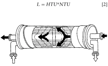
Figure 2 Schematic representation of a Liqui-Cel Extra-Flow membrane contactor.
single-pass continuous counter-current operation can reach further extraction, depending on the Rbre length andSow rates. For not such a high degree of extraction, the design equations must be looked at so as to choose the mode that minimizes the costs in-herent in the desired extraction.
Commercially Available Membrane Contactors
The best known module is the Liqui-Cel威 Extra-Flow, marketed by Celgard LLC (Figure 2). This module uses Celgard microporous polypropylene
Rbres, up to 22 500, that are woven into a fabric and wrapped around a central tube feeder that supplies the shell side Suid. It also contains a central shell side bafSe that improves efRciency by minim-izing shell side bypassing and provides a component of normal velocity to the membrane surface, which results in higher mass transfer coefRcients than those achieved with strictly parallelSow. The larger modules can operate with liquid Sow rates up to several thousand litres per minute.
Also, commercial hollow-Rbre microRltration and ultraRltration modules with hydrophilic membranes, generally with parallelSow, can also be used as mem-brane contactors.
For bubble-free gas}liquid mass transfer applica-tions, Membrane Corporation and W.L. Gore market modules with different nonporous membrane ar-rangements: theRrst with theRbres potted at one end only and individually sealed at the other end, so that all entering gas permeates the membrane; the second has the Rbres arranged as a helix, offering higher shell side mass transfer coefRcients than the par-allel conRguration.
Equipment Design
A hollow-Rbre membrane contactor is a continuous contact equipment and so the well-known concept of mass transfer unit is also applied here:
L"HTUHNTU [2]
whereHTUis the height of the transfer unit andNTU is the number of transfer units necessary for a given separation. This equation allows the evaluation of the height or length of the contactor necessary to obtain the required extent of mass transfer.
The mathematical description of this design equa-tion can be illustrated for an extracequa-tion process where the aqueous phase circulates in the tube side. In this case, a differential mass balance to the
hollow-Rbre module can be used to determine the change in solute concentration during a single pass:
!Qaq)dCt"Kt)dAm)(Ct!CHt) [3]
where Kt is the overall mass transfer coefRcient,
Qaq represents the aqueous-phaseSow rate, Am the
membrane transfer area, equal to.di.L.nf, wherenfis
the number ofRbres, andCtis the solute
concentra-tion in the tube side phase. The superscriptHrefers to the solute concentration in the tube side (aqueous phase) in equilibrium with the solute concentration in the shell side (organic phase).
Eqn [3] can be integrated for theRbre length. For the module inlet (z"0) Ct"Cint and for the outlet
(z"L) Ct"Coutt , where Cint and Coutt are the solute
concentrations entering and exiting the module, respectively:
L"HTUHNTU"vaq Ktai
Coutt
Cin t
dCt
CHt!Ct
[4]
wherevaqis the Suid velocity circulating in the tube
side,Ktis the module-averaged overall mass transfer
coefRcient and ai is the interfacial area per unit
module volume.
If a constant partition coefRcient, P, can be assumed during the extraction process, integration of eqn [4] usingCHt"Cs/PwhereCs, the solute
concen-tration in the shell side phase, is obtained by mass balance, yields an analytical expression for the con-tactor length. TheNTUexpressions for a hydropho-bic membrane with aqueous phase inRbre lumen and organic phase in the shell side, respectively for co-current Sow and counter-current Sow are the following:
NTU" 1
1# Qaq QorgP
lnC
out
t !Couts /P
Cin
t!Cins/P
[5]
NTU" 1
1! Qaq QorgP
lnC
in
t!Couts /P
Cout
t !Cins/P
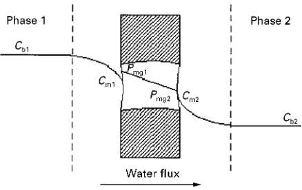
Figure 3 Concentration profiles and overall mass transfer resistance expressions for a chemical system with a solute partition coefficient favourable to the aqueous phase (P(1).
For gas}liquid separations the partition coefR c-ient may be replaced byH, Henry’s law constant, and the aqueous and organicSow rates replaced by liquid and gasSow rates.
For systems with a variable partition coefR c-ient it is necessary to introduce the equilibrium rela-tion betweenCHt andCsand a numerical integration is
required.
Evaluation of Mass Transfer Coef\cients
Three individual mass transfer resistances may be considered in membrane contactor extraction processes:
1. the inside tube boundary layer resistance
2. the membrane resistance to the solute diffu-sion through the pores
3. the shell side boundary layer resistance
The resistances are inversely proportional to the local mass transfer coefRcients and a function of the system’s geometry. Thus, for a hollow-Rbre system when the membrane is wetted by the shell side phase, we obtain:
1 Kt)Ai"
1 kt)Ai#
1 P)km)Alm#
1 P)ks)Ao
[7]
where Kt represents the overall mass transfer coef-Rcient (based on the tube side phase),kt,kmandksare
the local mass transfer coefRcients on the tube side, membrane and shell side, respectively, and Ai,
AoandAlmare theRbres’ internal, external and
logar-ithmic mean areas, respectively.
As the membrane may be hydrophobic or hy-drophilic and the aqueous phase may circulate either in the Rbre lumen or in the shell side, four differ-ent expressions for the overall mass transfer resist-ance for liquid}liquid extraction can be determined. Figure 3 shows the concentration proRles and the overall mass transfer resistances.
The tube side and the shell side mass transfer
coef-Rcients can be obtained experimentally and several correlations may be found in the literature.
Mass Transfer Correlations
Since laminar Sux is predominant in hollow-Rbre membrane contactors, a LeHve`que type equation can be used to correlate both the tube side and the shell side mass transfer coefRcients:
Sht")Scbtt )Rectt )
di
1
1/3
[8]
Shs")Scbss )Recss )
dh
1
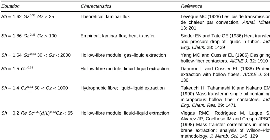
[9]Table 1 Mass transfer correlations for the tube side
Equation Characteristics Reference
Sh"1.62Gz0.33Gz'25 Theoretical; laminar flux LeHve`que MC (1928) Les Iois de transmission
de chaleur par convection. Annal. Mines 13: 201
Sh"1.86Gz0.33Gz'100 Empirical; laminar flux, heat transfer Sieder EN and Tate GE (1936) Heat transfer
and pressure drop of liquids in tubes.Ind. Eng. Chem. 28: 1429
Sh"1.64Gz0.3330(Gz(2000 Hollow-fibre module; gas}liquid extraction Yang MC and Cussler EL (1986) Designing
hollow-fiber contactors.AIChE J. 32: 1910
Sh"1.5Gz0.33 Hollow-fibre module; liquid}liquid extraction Dahuron L and Cussler EL (1988) Protein
extraction with hollow fibers. AIChE J. 34: 130
Sh"1.4Gz0.3350(Gz(1000 Hydrophobic fibre; liquid}liquid extraction Takeuchi H, Tahamashi K and Nakano EM
(1990) Mass transfer in single oil containing microporous hollow fiber contactors. Ind. Eng. Chem. Res. 29: 1471
Sh"0.2Re Sc0.33(d
[image:6.568.51.514.412.699.2]i/L)0.33Gz(65 Hollow-fibre module; liquid}liquid extraction Viegas RMC, RodrmHguez M, Luque S, Alvarez JR, Coelhoso IM and Crespo JPSG (1998) Mass transfer correlations in mem-brane extraction: analysis of Wilson}Plot methodology.J. Memb. Sci. 145: 129 Gz: Graetz number"Re Sc(di/L).
Table 2 Mass transfer correlations for the shell side
Equation Characteristics Reference
Sh"1.25(Redh/L)0.93Sc0.33 Hollow-fibre module; gas}liquid extraction Yang MC and Cussler EL (1986) Designing
hollow-fiber contactors.AIChE J. 32: 1910
Sh"8.8(dh/L)ReSc0.33Re(100 Hollow-fibre module; liquid}liquid extraction Dahuron L and Cussler EL (1988) Protein
extraction with hollow fibers. AIChE L. 34: 130
Sh"5.85(1!)dh/L)Re0.6Sc0.33 (0.2Re(500
Hollow-fibre module; liquid}liquid extraction Prasad R and Sirkar KK (1988) Dispersion-free solvent extraction with microporous hol-low fiber modules.AIChE J. 34: 177 Sh"0.85(dh/L)0.25
(de/ds)0.45Re0.33Sc0.33Re(700
Hydrophobic fibre; liquid}liquid extraction Takeuchi H, Tahamashi K and Nakano EM (1990) Mass transfer in single oil containing microporous hollow fiber contactors. Ind. Eng. Chem. Res. 29: 1471
Sh"0.017
(de/ds)0.57Re0.8Sc0.33700(Re(2000
Hydrophobic fibre; liquid}liquid extraction Takeuchiet al. (1990)
Sh"(0.53!0.58?)Re0.53Sc0.33 Hollow-fibre module; gas}liquid extraction Costello MJ, Fane AG, Hogan PA and
Scho-field RW (1993) The effect of shell side hy-drodynamics on the performance of axial flow in hollow fibre modules.J. Memb. Sci. 80: 1
Sh"8.7Re0.74(d
h/L) Sc0.33Re(50 Hollow-fibre module; liquid}liquid extraction Viegas RMC, RodrOHguez M, Luque S, Alvarez JR, Coelhoso IM and Crespo JPSG (1998) Mass transfer correlations in membrane ex-traction: analysis of Wilson}Plot methodo-logy.J. Memb. Sci. 145: 129
de, external fibre diameter;dsshell diameter;dhhydraulic diameter;packing factor"nfd2e/d2s. exponents of the Schmidt numbers (Sc),btandbs, are
usually 0.33; however, the exponents of the Reynolds numbers (Re), ct and cs, may be different from
that value.
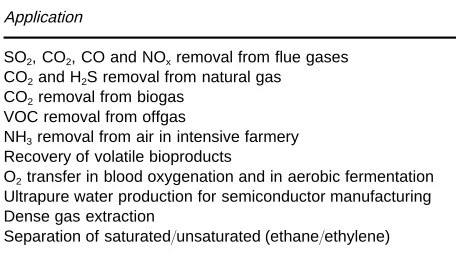
Table 3 Applications of membrane contactors on gas absorp-tion/stripping processes
Application
SO2, CO2, CO and NOxremoval from flue gases CO2and H2S removal from natural gas CO2removal from biogas
VOC removal from offgas
NH3removal from air in intensive farmery Recovery of volatile bioproducts
O2transfer in blood oxygenation and in aerobic fermentation Ultrapure water production for semiconductor manufacturing Dense gas extraction
Separation of saturated/unsaturated (ethane/ethylene)
Concerning the tube side, in most published works an exponent ofct"1/3 is usually obtained for a
high-er tube side Reynolds numbhigh-ers range. Howevhigh-er, using tube side Reynolds numbers in a low range (Re(50 andGz(100), values ofct"1 were reported.
For the shell side, the values of the exponent of the Reynolds number are 0.5(cs(1. Values of 0.5 for
laminarSow and 0.6 for turbulentSow on the shell side of a shell and tube heat exchanger are reported. Deviation from these values may be due to the nonuniform distribution of theRbres and their defor-mation by action of organic solvents, both inducing an irregular Sow due to the formation of stagnant zones, preferential pathways and deRcient mixing.
Applications
Liquid^Liquid Extraction
Liquid}liquid extraction cover quite a broad range of applications, including metal extraction, wastewater treatment and extraction of pharmaceutical and other products of biotechnological interest, such as organic acids and proteins.
Recovery of metals from industrial process waste-water is important, not only because metals are valu-able, but also because of environmental legislation restrictions. Several examples of metal extraction (Cu, Zn, Ni, Cr(VI), Cd) using membrane contactors, have been reported. Reactive extraction is usually employed and extractants such as organophosphor-ous compounds (TOPO, D2EHPA), tertiary amines
(tri-n-octylamine) and liquid ion exchangers (Aliquat 336) are used.
Extraction of pollutants from wastewater such as phenol, toluene and volatile organic compounds (VOCs) using methyl isobutyl ketone (MIBK), hexane and kerosene as solvents and also reactive extraction with several extractants were reported. A pilot-scale plant for extraction of chlorinated and aromatic com-pounds from industrial wastewaters in the Nether-lands was in operation for periods up to 3 months, reducing contaminant levels to 10g L\1.
Reactive extraction of organic acids produced by fermentation, such as acetic, citric, lactic and succinic acid, were also reported. Extraction of amino acids using reversed micelles was also studied.
Protein extraction can be accomplished either by two-phase aqueous extraction or by reversed micelles. Problems of interface stabilization caused by emulsions due to the adsorption of surfactant to the membrane surface, thus lowering the interfacial ten-sion, were reported. Careful control of the pressure difference across the membrane was required for a stable operation.
Gas}Liquid Contactors
In gas}liquid extraction with membrane contactors, most efforts have been conducted in the areas of gas absorption/stripping and of wastewater treat-ment. Other Relds like dense gas extraction and semiconductor cleaning water have been the object of study more recently.
Commercial applications include the Pepsi bottling plant in West Virginia that has been operating a bubble-free membrane-based carbonation line since 1993, showing reduced foaming, improved yield, lower CO2 pressures and increased Rlling speed at
high temperatures. Also, several beer production plants are using this technology for CO2 removal to
obtain a dense foam head, while others remove oxy-gen from beer to preserve itsSavour; the stripping of oxygen from water, which is then used to dilute beer, is also being applied. Other commercial applications include the treatment of boiler feedwater, stripping of CO2from anion exchange feed streams and ultrapure
water production for semiconductor manufacture. In wastewater treatment, air stripping of VOC has been studied using polypropylene hollow Rbres to remove chloroform, tetrachloroethylene, carbon tetrachloride, 1,1,2-trichloroethane and trich-loroethylene from aqueous streams. Also, several studies have reported the use of membrane contactors for bubble-free aeration in wastewater treatment. Ad-vantages include the absence of foaming, higher aer-ation rates, lower power input and ability to handle solids.
A list of applications is summarized inTable 3.
Membrane Distillation
Figure 4 Schematic representation of water transport in osmo-tic distillation.
solutions corresponding to a difference in vapour pressure at both ends of the membrane. It may also be due to the different nature and concentration of the solute components of both phases, thus causing a different osmotic pressure of the two liquids. Since the osmotic pressure of an electrolyte solution is about 10 times higher than an equimolar solution of electrically uncharged particles, salt solutions (NaCl, CaCl2, KH2PO4) are efRcient and relatively cheap
systems to create high osmotic pressure differ-ences. In both cases, water evaporates in the solution of higher chemical potential and the water vapour formed is transported across the membrane pores before being condensed in the solution of the lower water potential (Figure 4).
Solutions whose vapour pressure is relatively unaf-fected by the presence of the solute are ideal candi-dates for concentration using osmotic distillation. This includes solutions consisting primarily of sugars, such as fruit juices.
Two pilot-plant facilities located in Melbourne and Mildura (Australia) are successfully operating for concentration of fruit juices. Colour, Savour and aroma retention is good due to the lower operating temperature and stresses.
Grape juice concentrates used for production of high quality wines may also be concentrated by mem-brane distillation. Since these concentrates are stable for long periods of storage they can be shipped over long distances and high priced wines can be produced in regions where these grapes are not available or are too expensive.
Opportunities also exist for the concentration of pharmaceutical products, which are susceptible to thermal degradation.
Biphasic Membrane Bioreactors
Multilayer membrane bioreactors can readily be constructed from several membrane Rlms to which different biocatalysts have been attached or from
combinations of permselective and catalytic membranes.
The use of permselective membranes in conjunc-tion with catalyticRlms (or catalytic compartments) makes possible a high degree of control over the
Suxes of the reaction participants, and hence over the course of reaction, that is impossible to achieve with catalyst particles. By using an adequate permselective membrane theSuids on either side of a membrane can be segregated, thus providing an additional degree of freedom in reactor design.
Most research work has been oriented to the devel-opment of biphasic membrane bioreactors where a microporous (hydrophobic or hydrophilic) mem-brane is used to separate an aqueous from an organic compartment. In this way, two immiscible liquid phases can be contacted across a membrane without one of the phases having to be dispersed in the other, as is required in most conventional multiphase reac-tion systems. In this type of reactor the biocatalyst may be linked to the membrane (Figure 5) or dis-persed in one of the bulk phases.
The opportunity for development of biphasic mem-brane bioreactors is quite clear: the demand for selec-tive removal of deRned pollutants and the need for enantioselective transport and reaction for chiral syn-thesis in the pharmaceutical and food industries re-quire new approaches in thisReld. Special attention has been devoted to the development of biphasic membrane bioreactors for enzymatic esteriRcation and hydrolysis reactions.
Future Developments
Membrane contactors are unique equipment for pro-moting mass transfer while avoiding the dispersion of theSuid phases involved. This article has brieSy re-viewed the potential of membrane contactors in dif-ferent areas of application and the problems which are still to be solved.
The industrial future of membrane contactors for liquid}liquid extraction processes, and in some
de-Rned situations for gas absorption, will depend very strongly on the ability to synthesize speciRc carriers or receptors with the potential to achieve recognition of individual solutes. Therefore, the trend will be the development of very selective carriers, in some cases with the ability for chiral recognition.
Membrane stability, in the sense of avoiding con-tamination between the two contacting Suids, is of major importance for the penetration of membrane contactors in some industrial markets. In particular, in the food and the pharmaceutical industries, trace contamination between the twoSuid phases is a
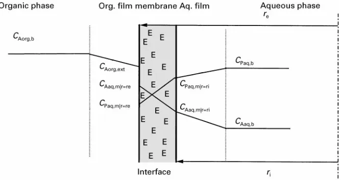
Figure 5 Representation of the enzymatic conversion of a substrate (subscript A) soluble in the organic phase to a product (subscript P) soluble in the aqueous phase. The enzyme is entrapped inside the porous structure of a hydrophilic membrane.
Development of organic solvents which are insoluble in water, nonvolatile and without the tendency to form emulsion would be highly desirable. Recently, the development of ionic liquids has been reported in the literature. These are entirely comprised of ions (complete absence of water), and are nonvolatile and insoluble in water. This type of solvent opens a world of new opportunities for liquid}liquid extraction and gas absorption using membrane contactors, without the risk ofSuid cross-contamination. Also the use of dense gases and supercritical Suids has been sugges-ted in membrane contactors. Again, the problem of contamination with the solvent phase could be eliminated.
Finally, new module design and new manu-facturing materials will be welcome for certain type of applications, especially when viscous Suids and aggressive solvents are used. Further increases in membrane contactor performance are expected with the use of hollow-Rbre fabrics and bafSed modules.
Further Reading
Cussler EL (1994) HollowRber contactors. In: Crespo JG and Boddeker KW (eds)Membrane Processes in Separ-ation and PuriTcation. Dordrecht: Kluwer Academic Publishers.
Gabelman A and Hwang S-T (1999) Hollow Rber mem-brane contactors. Journal of Membrane Science 159: 61}106.
Hogan PA, Canning RP, Petersen PAet al. (1998) A new option: osmotic distillation. Chemical Engineering Progress49}61.
Kunz W, Behabiles A and Ben-Aim R (1996) Osmotic evaporation through macroporous hydrophobic membranes: a survey of current research and ap-plications. Journal of Membrane Science 121: 25}36.
Matson SL and Quinn JA (1992) Membrane reactors. In: Ho WSW and Sirkar KK (eds)Membrane Handbook. New York: Chapman&Hall.
Mulder M (1996) Basic Principles of Membrane
Technology, 2nd edn. Dordrecht: Kluwer Academic
Publishers.
Prasad K and Sirkar KK (1992) Membrane-based solvent extraction. In: Ho WSW and Sirkar KK (eds)Membrane Handbook. New York: Chapman & Hall.
Reed BW, Semmens MJ and Cussler EL (1995) Membrane contactors. In: Noble RD and Stern SA (eds)Membrane Separations Technology. Principles and Applications. Dordrecht: Kluwer Academic Publishers.
Viegas RMC, Rodriguez M, Luque Set al. (1998) Mass transfer correlations in membrane extraction: analysis of Wilson-plot methodology.Journal of Membrane Science