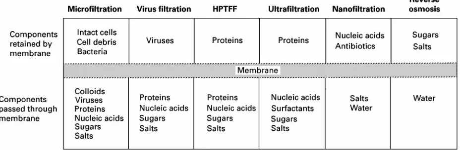
Figure 1 Classification of pressure-driven membrane processes showing typical bioprocessing applications. Boyadzhiev L (1990) Liquid pertraction or liquid
mem-branes}state of the art.Separation Science and Techno-logy25: 187.
Boyadzhiev L and Lazarova Z (1994) Liquid membranes (liquid pertraction). In: Noble RD and Stren SA (eds) Membrane Separation Technology. Principles and Applications, pp. 283}352. Amsterdam: Elsevier. Drioli E and Nakagaki M (1986)Membranes and
Mem-brane Processes. New York: Plenum.
Ho WSW and Sirkar KK (eds) (1993) Membrane Hand-book. New York: Van Nostrand Reinhold.
Li NN (1971) Permeation through liquid surfactant membranes.American Institute of Chemical Engineers Journal17: 459.
Noble RD and Douglas Way J (eds) (1996)Liquid Mem-branes. Theory and Application. American Chemical Society Symposium Series no 347. Washington, DC: American Chemistry Society .
Zhang R (ed.) (1984) Separation Techniques by Liquid Membranes (in Chinese). Nanchang: Jiangxi Renmin.
Membrane Bioseparations
A. L. Zydney, University of Delaware, Newark, DE, USA
Copyright^ 2000 Academic Press
Membrane processes are particularly well suited to the separation and puriRcation of biological mol-ecules since they operate at relatively low tempera-tures and pressures and involve no phase changes or chemical additives. Thus, these processes cause mini-mal denaturation, deactivation and/or degradation of highly labile biological cells or macromolecules. Al-though essentially all membrane processes (Figure 1) have been used for bioseparations, the greatest inter-est has been in the application of the pressure-driven processes of ultraRltration (UF) and microRltration (MF). UltraRltration membranes have pore sizes be-tween 1 and 50 nm and are used for protein concen-tration, buffer exchange, desalting, clariRcation of antibiotics and virus clearance. There is also growing interest in the use of ultraRltration for protein puriR -cation using high performance tangentialSowR ltra-tion (HPTFF). MicroRltration membranes have a pore size between 0.05 and 10m and are thus used
for initial clariRcation of protein solutions, cell harvesting and sterileRltration. In addition, ultraR l-tration and microRltration of blood are used for the treatment of a variety of metabolic and immunolo-gical disorders.
The development of membrane processes for bio-separations is very similar to the design of membrane systems for nonbiological applications. However, there are some important differences including:
1. increased concerns about deactivation or de-naturation of biological molecules and cells 2. very high value (on a per unit mass basis) of most
biological products (particularly recombinant therapeutic proteins)
3. tendency of biological macromolecules and cells to cause signiRcant fouling of both ultraRltration and microRltration membranes
4. critical importance of validation and integrity test-ing in bioprocesstest-ing applications
underlying principles governing the design of ultraR l-tration and microRltration systems, with particular emphasis on those factors that are most signiRcant for bioseparations. The reader is referred to the Encyclo-pedia articles on Membrane Separations}MicroR l-tration and Membrane Separations }UltraRltration for more detailed discussions of these membrane technologies.
Historical Development
TheRrst mention of the process now known as ultra-Rltration appears to have been in an 1856 study by Schmidt on theRltration of protein and gum arabic through animal membranes. Thus, the idea of using ultraRltration for bioseparations dates back well over 100 years. Bechhold coined the term ultraRltration in 1906 during a systematic study of the behaviour of different pore size collodion membranes made by impregnatingRlter paper with acetic acid and cellu-lose nitrate. Zsigmondy obtained one of the Rrst patents in membrane technology in 1922 for the prep-aration of Sat collodion membranes from ether} alcohol solutions. TheRrst efforts to develop micro-porous membranes in the USA were motivated by the need for rapid detection and analysis of biological warfare agents. This technology was subsequently transferred to the Lovell Chemical Company, which ultimately led to the establishment of Millipore Cor-poration.
The early historical development of ultraRltration and microRltration is described in an excellent review article by Ferry in 1936. The primary applications of membrane technology in the early 1900s were for a variety of biological, analytical and bacteriological assays. Ferry also described the use of membranes for enzyme concentration, analysis of bacteriophages and viruses, blood ultraRltration to prepare cell- and protein-free ultraRltrates, sterile Rltration of bio-logical solutions and the partial separation of al-bumin from globulins in blood serum. All of these bioseparations remain areas of active commercial in-terest even today.
Although many of the potential uses of membrane systems in bioprocessing were identiRed well over 60 years ago, the collodion (cellulose nitrate) mem-branes available at that time had inadequate chem-ical, mechanical and mass transport properties for the effective use of ultraRltration on an industrial scale. The key breakthrough was the development of the asymmetric cellulose acetate reverse osmosis mem-brane by Loeb and Sourirajan in the early 1960s and the subsequent extension of this technique to produce asymmetric ultraRltration membranes. These asym-metric membranes have a very thin skin
(approxim-ately 0.5m thick), which provides the membrane with its selectivity, and a more macroporous sub-structure, which provides the required mechanical and structural integrity. The thin skin results in much higher permeation rates than are obtainable with homogeneous membranes, signiRcantly reducing the required membrane area and/or process time.
UltraRltration is now used throughout the down-stream separation process for the puriRcation of therapeutic recombinant proteins, blood compo-nents, natural protein products and industrial enzymes. SpeciRc applications include protein con-centration (i.e. volume reduction), desalting and buf-fer exchange, all of which are used to condition the product prior to, or immediately after, other separ-ation processes or as part of theRnal product formu-lation. In addition, ultraRltration is used extensively for the clariRcation of antibiotics, amino acids and other small biological molecules. Recent work has demonstrated that ultraRltration membranes are also capable of effecting protein}protein separations using a process known as HPTFF. MicroRltration mem-branes are used for cell harvesting, initial clariRcation of cell culture media and fermentation broths, and for sterileRltration of products that are directly added to pre-sterilized containers. SterileRlters are also used to remove bacteria and particles from feedstock solu-tions and to reduce the overall bioburden in processes where the product will be subjected to a terminal sterilization step. Virus removal membranes are used as part of the overall viral clearance required for the production of therapeutic proteins and blood prod-ucts. VirusRlters can also provide a protective barrier for bioreactors through the Rltration of media and buffer solutions.
Ultra
\
ltration and Micro
\
ltration
Principles
Membrane Selection
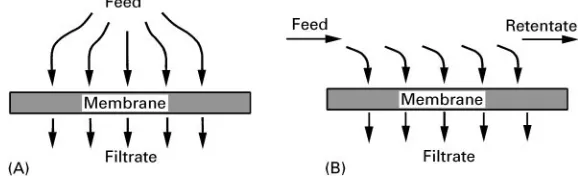
Figure 2 Comparison of (A) dead-end and (B) cross-flow configurations. render them more hydrophilic to reduce protein
ad-sorption and fouling. Membranes used for sterileR l-tration must be steam-sterilizable, have minimal par-ticle shedding, low extractables and must pass United States Pharmacopoeia (USP) Class VI toxicity testing. Most manufacturers rate ultraRltration membranes by their nominal molecular weight cutoff, which is deRned as the molecular weight of a solute with a particular retention coefRcient:
R"1!Cfiltrate/Cfeed [1]
whereCfiltrateandCfeedare the solute concentrations in the Rltrate solution and feed stream, respectively. Data are typically obtained with a range of model proteins or with polydisperse dextrans. Unfortun-ately, the procedures used for assigning molecular weight cutoffs, including the choice of solutes, the speciRc buffer and Sow conditions, and the chosen retention value (usually R"0.9) vary widely throughout the industry. In addition, ultraRltration systems used in bioprocessing generally require pro-tein retention of at least 99%, and often as high as 99.9%, to minimize loss of high value products through the membrane. Data obtained with solutes havingR"0.9 are often of little value in determining whether a given membrane can provide these high levels of protein retention due to differences in the details of the pore size distributions.
MicroRltration membranes are typically rated by their pore size or their particle retention character-istics using the log reduction value (LRV), deRned as the logarithm (base 10) of the ratio of the particle, cell or virus concentration in the feed to that in theRltrate solution. Sterilizing-grade (0.2m pore size) Rlters are currently deRned by the Health Industry Manu-facturing Association (HIMA) as a Rlter which pro-duces a sterileRltrate when challenged by 107 colony-forming units ofBrevundimonas diminuta(formerly classiRed asPseudomonas diminuta) per cm2of mem-brane area. This challenge uses the smallest bacteria at a concentration that exposes essentially every pore to the microorganisms. Sterile Rlters are often thought of as operating via a purely size-based
(siev-ing) mechanism, although bacteria can also be re-moved by adsorption on to the membrane surface.
The chemical compatibility of the membrane needs to be veriRed with the feed, regeneration chemicals and storage solutions. Sodium hypochlorite (NaOCl) is used most extensively for chemical disinfection of membrane systems in bioprocessing applications. Many membrane systems are designed for steam-in-place (SIP) sterilization, with the entire unit exposed toSowing steam as part of the completely assembled Rltration system. Minimum requirements for an effective steam sterilization are 15 min exposure to steam at 1213C and 1 atm pressure. Polysulfone membranes tend to have broader chemical and ther-mal stability than cellulosic membranes but also re-quire harsher chemical treatment for regeneration due to their greater fouling characteristics. Inorganic (ceramic) membranes have the greatest chemical compatibility, but they are much more expensive than polymeric membranes. The mechanical strength of the membrane is important since reverse-pressure spikes can cause membrane delamination and cata-strophic yield loss.
Module Design
Dead-end, or normal-Sow, Rltration (Figure 2A) is used primarily for laboratory-scale separations and for systems in which the retained species are present at very low concentration. For example, dead-end microRltration cartridges are used extensively for sterileRltration since the retained bacteria are present at very low concentration. Similar modules can be employed for virus removal applications. Almost all large scale commercial ultraRltration devices use tan-gentialSowRltration, also referred to as a cross-Sow conRguration, in which the feedSow is parallel to the membrane and thus perpendicular to theRltrateSow (Figure 2B). This allows retained species to be swept along the membrane surface and out of the device exit, signiRcantly increasing the process Sux com-pared to that obtained with dead-end operation.
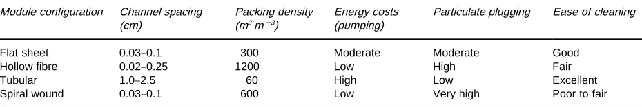
Table 1 Comparison of different module configurations Module configuration Channel spacing
(cm)
Packing density (m2m\3)
Energy costs (pumping)
Particulate plugging Ease of cleaning
Flat sheet 0.03}0.1 300 Moderate Moderate Good
Hollow fibre 0.02}0.25 1200 Low High Fair
Tubular 1.0}2.5 60 High Low Excellent
Spiral wound 0.03}0.1 600 Low Very high Poor to fair
processes, differing primarily in the size and shape of the feed andRltrateSow channels.Table 1provides a general summary of the physical characteristics of the most common modules. Detailed descriptions of these modules are available elsewhere.
The small channel spacing in Sat-sheet, hollow-Rbre and spiral-wound modules provides high mem-brane-packing densities. In addition, these modules have low hold-up volumes, which facilitates the re-covery of high value products. The screens used to deRne the Sow path in spiral-wound modules and many Sat-sheet cassettes are susceptible to particle plugging and this may make cleaning more difRcult. Hollow-Rbre membranes are self-supporting, so they can often be cleaned by simple backSushing. The large-bore tubular membranes can be cleaned by both physical and chemical methods. However, these mod-ules operate in the turbulentSow regime which can cause cell lysis, protein denaturation or aggregation. A variety of enhanced mass transfer modules which exploitSow instabilities have also been developed for bioprocessing applications. Rotating cylinder mod-ules which induce Taylor vortices have very high mass transfer rates, although there are concerns about the moving parts. Another attractive approach is to use helically coiled hollow Rbres wrapped around a central core to induce Dean vortices.
Process Con\gurations
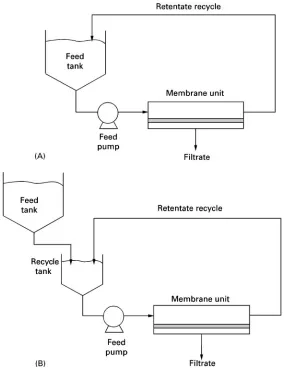
Protein concentration can be carried out using either batch or fed-batch operation (Figure 3). In a batch process, the entire feed volume is contained within the recycle tank. Tank design is critically important to ensure adequate mixing while avoiding air entrain-ment and excessive foaming. Batch operation uses a minimum of hardware and allows simple manual or automatic control. The Sux rates are also higher in batch processes since the bulk concentration follows a more dilute path in going from initial toRnal con-centration. Disadvantages of the batch conRguration include less Sexibility in using the same system for multiple processes, greater difRculty in designing a well-mixed system, and difRculties in obtaining high concentration factors.
The fed-batch conRguration utilizes an additional tank to feed into the recycle tank (Figure 3). Fed-batch conRgurations are commonly used to obtain high concentration factors and to provide well-mixed, low-hold-up, retentate reservoirs. These sys-tems also provideSexibility for use in multiple pro-cesses. The disadvantages of the fed-batch system include greater process time and greater number of passes of the retentate through the pumps and valves in the recycle line. The latter can lead to excessive cell lysis, protein denaturation or aggregation.
DiaRltration is commonly used for buffer exchange (for products in the retentate) and to enhance yield (for products in theRltrate). The diaRltration system looks similar to the fed-batch conRguration shown in Figure 3 except that the feed tank contains a buffer solution which is added to the recycle tank. The most common approach is constant retentate volume dia-Rltration in which the buffer is added at the same rate asRltrate removed.
The yield and puriRcation obtained in ultraR ltra-tion and microRltration processes can be evaluated from simple mass balances on the product and im-purity assuming constant rejection coefRcients. The Rnal product concentration (CF) at the end of a batch concentration process is given as:
CFC0
"
V0VF
1\S[2]
whereVFis theRnal retentate volume,V0is the initial retentate volume andSis the product sieving coefR c-ient (equal to one minus the rejection coefRcient). The analogous expression for a fed-batch process is:
CF
C0"
1
S#
1! 1S
exp!S V0VF!
1
[3]The Rnal concentration after a constant retentate volume diaRltration is:
CF
C0"
Figure 3 Comparison of (A) batch and (B) fed-batch processes for protein concentration.
where the number of diavolumes (N) is given by:
N"VD/V [5]
whereVDis the diaRltration buffer volume. Even very small sieving coefRcients may result in substantial product loss when a large number of diavolumes are required in diaRltration processes. For example, a diaRltration process with a product sieving coefR c-ient of S"0.01 will result in a 10% product loss during a 10 diavolume buffer exchange.
Concentration Polarization
One of the critical factors determining the overall performance of tangentialSowRltration devices is the rate of solute/particle transport in the bulk solution adjacent to the membrane. TheRltrateSow causes an accumulation of partially (or completely) retained components at the upstream surface of the mem-brane, a phenomenon referred to as concentration
polarization. The concentration thus varies from its maximum value at the membrane surface (Cw) to its bulk value (Cb) over the thickness of the concentra-tion boundary layer (). Most analyses of concentra-tion polarizaconcentra-tion have employed the simple stagnant Rlm model in which:
J"kln
Cw!CfCb!Cf
[6]
protein solubility limit or the concentration at which the osmotic pressure of the retained solutes is essen-tially equal to the applied transmembrane pressure. The net result is that theSux attains a nearly constant pressure-independent value that increases with de-creasing bulk concentration and inde-creasing feed Sow rate. The dependence on feedSow rate is determined by the module characteristics: approximately 1/3 power for laminar Sow in hollow Rbres and open channels, 1/2 power for screened channels, and 0.8 power for turbulent Sow in tubular modules. The dependence on feedSow rate for cellular suspensions is typically greater than that for protein solutions due to shear-induced particle diffusion and inertial lift effects.
Process Control
UltraRltration and microRltration processes have tra-ditionally been performed at constant transmem-brane pressure. Constant-pressure processes are very simple to control. The feed rate is ramped up to the set point and the retentate valve is then partially closed to obtain the desired transmembrane pressure. The transmembrane pressure should be gradually in-creased to minimize fouling. In some applications it may not be possible to maintain constant transmem-brane pressure without severe reductions in Rltrate Sux over the course of the process due to membrane fouling. This is particularly true for cell microR ltra-tion where the high initial Sux leads to very rapid deposition of cells and cell debris on the membrane surface. Several studies have shown that higher over-all throughput can often be obtained in these applica-tions by operating at constantRltrateSux. TheSux is controlled by regulating the retentate pressure control valve or by using a pump on theRltrate line.
A third method of process control that is very attractive for bioprocessing applications is to vary the RltrateSux so that the wall concentration of retained species (evaluated from eqn [6]) remains constant during the process. Control is performed using a pro-portional-integral-derivative (PID) loop that mea-suresSux and controls the transmembrane pressure orRltrateSow rate to maintain a constant wall con-centration throughout the process. The beneRts of constant Cw control are that product yield is maxi-mized, product quality is ensured, membrane area is minimized and process time is consistent and inde-pendent of variations in membrane permeability.
High Performance Tangential Flow
Filtration
UltraRltration and microRltration have traditionally been limited to separating species that differ in size by
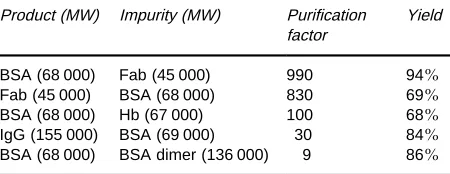
at least 10-fold. In contrast, HPTFF enables the sep-aration of solutes without limit to their relative size. HPTFF is able to obtain the high selectivity required for effective protein puriRcation by exploiting several recent developments. Firstly, HPTFF is operated in the pressure-dependent regime, with theRltrateSux and deviceSuid mechanics chosen to minimize foul-ing and exploit the effects of concentration polariza-tion. Since optimal separation in HPTFF is obtained at a speciRc Rltrate Sux, the membrane module should be designed to maintain a nearly uniformSux and transmembrane pressure throughout the module. This can be done using a co-currentRltrate Sow to balance the feed-side pressure drop through the mod-ule. Secondly, the buffer pH and ionic strength are adjusted to maximize differences in the effective vol-ume of the different species. The effective volvol-ume of a charged protein (as determined by size exclusion chromatography) accounts for the presence of the diffuse electrical double layer surrounding the pro-tein. Protein transmission through the membrane can be reduced by increasing the effective protein volume, e.g. by increasing the net protein charge (by adjusting the pH) or by increasing the double-layer thickness (by reducing the solution ionic strength). Thirdly, the electrical charge of the membrane is chosen to in-crease the electrostatic exclusion of all species with like charge. Thus, a positively charged membrane will provide much greater rejection of a positively charged protein than will a negatively charged membrane of the same pore size. Fourthly, protein separations in HPTFF are accomplished using a diaRltration mode to wash the impurity (or product) out of the retentate. The diaRltration maintains an appropriate protein concentration in the retentate throughout the separ-ation, and it allows one to obtain puriRcation factors for products collected in the retentate that are much greater than the membrane selectivity due to the con-tinual removal of impurities in theRltrate.
Table 2 Purification factors and yields for HPTFF processesa
Product (MW) Impurity (MW) Purification factor
Yield
BSA (68 000) Fab (45 000) 990 94%
Fab (45 000) BSA (68 000) 830 69%
BSA (68 000) Hb (67 000) 100 68%
IgG (155 000) BSA (69 000) 30 84%
BSA (68 000) BSA dimer (136 000) 9 86%
aBSA, Bovine serum albumin; Fab, antigen-binding fragment from
recombinant DNA antibody; Hb, bovine haemoglobin; IgG, human immunoglobin.
smaller monomer collected in theRltrate. However, electrostatic interactions are also important in this system due to the combined effects of size and charge on protein transmission and to possible differences in the charge}pH proRles for the monomer and dimer.
Validation and Integrity Testing
Membrane systems used in bioprocessing applica-tions need to be validated to demonstrate consistent puriRcation and yield with minimal alteration in the properties of the product. Food and Drug Adminis-tration regulations provide speciRc guidelines for vali-dation of sterileRlters and virus removal membranes. Validation should always be performed at the same pH, ionic strength and chemical environment as used in the actual process to ensure equivalent physical and chemical characteristics of the product and impu-rities. Viral clearance studies are typically performed by spiking high titre infectious viruses (with different physical characteristics) into scaled-down production systems.
Integrity testing is critical for all sterile and viral Rlters to ensure that the system operates at the re-quired level of performance. Integrity tests should be performed both prior to, and immediately after, the actual process wherever possible. Integrity tests per-formed prior toRltration must not affect the sterility of the connections downstream of theRlter. The real test for the sterileRlter would be to challenge withB. diminuta, but the Rlter could not be used after this test. Thus, a number of surrogate nondestructive in-tegrity tests have been developed. The industry stan-dards are forward Sow, pressure decay and bubble point. Each of these tests is based on the displacement of a Suid from the pores by a secondSuid (or gas), with the rate of displacement providing a measure of the membrane pore size characteristics. The gas or intrusion liquid expels the wetting liquid out of the pore when the feed pressure exceeds the capillary force within the pore. The bubble point is deRned as
the pressure at which the pore isRrst intruded by the gas. The bubble point for sterilizing gradeRlters can be correlated to the LRV ofB.diminuta. Filters with water bubble points of 55 psi or greater typically yield the necessary LRV to be qualiRed as sterilizing-gradeRlters. In the forwardSow test, one measures the total gasSow rate through the wetted membrane at aRxed pressure. HighSow rates indicate the pres-ence of pressure-driven Sow through gas-intruded (large) pores. The pressure decay test is performed in a similar fashion, with the gasSow calculated from the rate of pressure decay. A variety of automated integrity test instruments have been developed by the different membrane manufacturers.
Bubble point tests with water-wetted membranes cannot be used to verify virusRlter performance since the bubble points for these small pore size membranes would exceed the membrane pressure limits. Air dif-fusion and bubble point tests can be performed on these membranes using wetting Suids having lower surface tension (e.g. isopropyl alcohol). Liquid intru-sion tests using two immiscibleSuids (e.g. solutions of a sulfate salt and polyethyleneglycol) have been developed as integrity tests for virus Rlters and HPTFF membranes.
Summary
Membrane processes should continue to be of critical importance in bioprocessing applications, facilitating the cost-effective production of a wide range of biolo-gical products. UltraRltration has become the primary means for protein concentration and buffer exchange in the production of therapeutic proteins and indus-trial enzymes. SterileRltration is used throughout the bioprocessing industry, and viralRltration is of grow-ing importance in the production of blood products and therapeutic recombinant proteins.
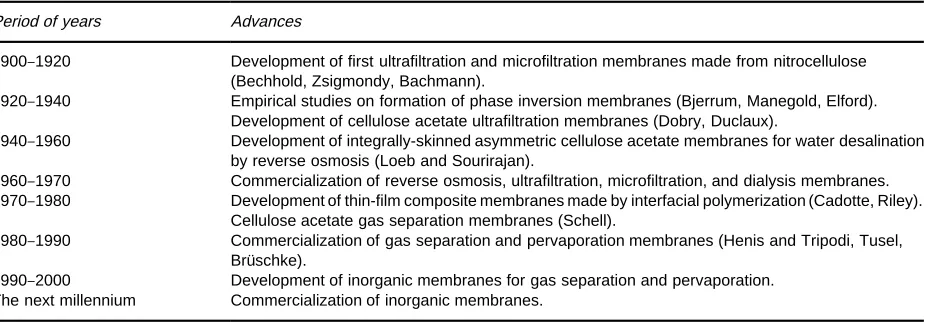
Table 1 Major milestones in the development of membranes for industrial separations
Period of years Advances
1900}1920 Development of first ultrafiltration and microfiltration membranes made from nitrocellulose (Bechhold, Zsigmondy, Bachmann).
1920}1940 Empirical studies on formation of phase inversion membranes (Bjerrum, Manegold, Elford). Development of cellulose acetate ultrafiltration membranes (Dobry, Duclaux).
1940}1960 Development of integrally-skinned asymmetric cellulose acetate membranes for water desalination by reverse osmosis (Loeb and Sourirajan).
1960}1970 Commercialization of reverse osmosis, ultrafiltration, microfiltration, and dialysis membranes. 1970}1980 Development of thin-film composite membranes made by interfacial polymerization (Cadotte, Riley).
Cellulose acetate gas separation membranes (Schell).
1980}1990 Commercialization of gas separation and pervaporation membranes (Henis and Tripodi, Tusel, BruKschke).
1990}2000 Development of inorganic membranes for gas separation and pervaporation. The next millennium Commercialization of inorganic membranes.
should lead to continued development of membrane systems for bioseparations.
See also: II / Membrane Separations: Microfiltration; Ultrafiltration.
Further Reading
Belfort G, Davis RH and Zydney AL (1994) The behavior of suspensions and macromolecular solutions in
cross-Sow microRltration.Journal of Membrane Science96: 1. Blatt WF, Dravid A, Michaels AS and Nelsen L (1970) Solute polarization and cake formation in membrane ultraRltration. Causes, consequences, and control tech-niques. In: Flinn JE (ed.)Membrane Science and Techno-logy, pp. 47}97. New York: Plenum Press.
Cheryan M (1997) UltraTltration and MicroTltration Handbook. Lancaster, PA: Technomic.
Ferry JD (1936) UltraRlter membranes and ultraRltration. Chemical Reviews18: 373.
Ho WSW and Sirkar KK (eds) (1992)Membrane Hand-book. New York: Chapman&Hall.
Lonsdale HK (1982) The growth of membrane technology. Journal of Membrane Science10: 81.
McGregor WC (ed.) (1986) Membrane Separations in Biotechnology. New York: Marcel Dekker.
van Reis R and Zydney AL (1999) Protein ultraRltration. In: Flickinger MC and Drew SW (eds)Encyclopedia of Bioprocess Technology:Fermentation,Biocatalysis,and Bioseparation, pp. 2197}2214. New York: John Wiley. Zeman LJ and Zydney AL (1996) MicroTltration and UltraTltration:Principles and Applications. New York: Marcel Dekker.
Membrane Preparation
I. Pinnau, Membrane Technology and Research,
Inc., Menlo Park, CA, USA
Copyright^ 2000 Academic Press
Background
A membrane (Latin,membrana, skin) is a thin barrier that permits selective mass transport. Between 1850 and 1900, membranes were used to derive basic phys-ical principles for gas and liquid transport across a barrier material (see the work of Mitchell, Fick and Graham). In these early studies it was already recog-nized that membranes could be used to separateSuid mixtures. Membranes used at that time included denseRlms of nitrocellulose, natural rubber, and pal-ladium. The Rrst commercial synthetic membranes