Burst-by-Burst Adaptive Multiuser Detection
CDMA: A Framework for Existing and Future
Wireless Standards
EE-LIN KUAN, MEMBER, IEEE AND
LAJOS HANZO, SENIOR MEMBER, IEEE
Contributed Paper
This paper provides a broad overview of the multiuser detection literature of the past few years in a nonmathematical, easily acces-sible approach. The treatment is then extended to the comparative study of channel-quality controlled burst-by-burst (BbB) adaptive code division multiple access (CDMA) detection such as parallel interference cancellation, successive interference cancellation, and joint detection (JD). It is demonstrated that the best complexity versus performance tradeoff is constituted by the JD receivers. Furthermore, the BbB-adaptive variable spreading factor-based schemes considered were outperformed by the adaptive quadrature amplitude modulation-based JD-CDMA schemes investigated. For example, at a channel signal-to-noise ratio per bit value of
Eb=N0 = 14 dB the latter scheme provides an average bit per symbol (BPS) throughput of 3.39, while the former provides an average BPS throughput of only 2.83, although the complexity of the latter is lower. In conclusion, BbB-adaptive CDMA schemes provide an attractive performance versus complexity tradeoff and are amenable to employment in both existing and future generations of wireless systems.
Keywords—Adaptive CMDA systems, adaptive transceivers,
in-terference cancellation, multiuser detection.
I. MOTIVATION
Mobile propagation channels exhibit time-variant propaga-tion properties [1]. Although, apart from simple cordless tele-phoneschemes, most mobileradiosystems employ powercon-trol for mitigating the effects of received power fluctuations, rapid channel quality fluctuations cannot be compensated by practical, finite reaction-time power control schemes. Further-more, the ubiquitous phenomenon of signal dispersion due to the multiplicity of scatering and reflecting objects cannot be mitigated by power control. Similarly, other performance
lim-Manuscript received November 1, 2001; revised October 7, 2002. This work was supported in part by the Engineering and Physical Sciences Re-search Council and in part by the European Commission.
E. L. Kuan and L. Hanzo are with the Department of Electronics and Computer Science, University of Southampton, Southampton SO17 1BJ, U.K. (e-mail: [email protected]; http://www-mobile.ecs.soton.ac.uk).
Digital Object Identifier 10.1109/JPROC.2002.808152
iting factors, such as adjacent-channel and cochannel interef-erence as well as multiuser interfinteref-erence (MUI) vary as a func-tion of time. The ultimate channel quality metric is the bit-error rate (BER), regardless of the specific channel impairments en-countered. The channel quality variations are typically higher near the fringes of the propagation cell or when moving from an indoor scenario to an outdoor cell due to the high standard deviation of the shadow fading and fast fading [1] encountered, even in conjunction with agile power control. Furthermore, the bit errors typically occur in bursts due to the time-variant channel quality fluctuations; hence, it is plausible that a fixed transceiver mode cannot achieve a high flexibility in such en-vironments.
The design of powerful and flexible transceivers [2]–[4] has to be based on finding the best compromise among a number of contradicting design factors [2]–[4]. Some of these factors are low power consumption, high robustness against transmis-sion errors among various channel conditions, high spectral efficiency, low- delay for the sake of supporting interactive real-time multimedia services, high-capacity networking, and so forth [5]. In this paper, we will address a few of these is-sues in the context of direct sequence code division multiple access [6] (DS-CDMA) systems,1 since CDMA is the solu-tion standardized in all three recently ratified global mobile
1The simple philosophy of DS-CDMA is that a binary bit of a user is
sig-naled to the receiver with the aid of a unique, user-specific signature sequence. The DS spreading sequences may be chosen such that they are orthogonal to each other; hence, the individual users’ signals do not interfere with each other, provided that the transmission channel does not destroy the orthog-onality of the DS spreading sequences. When the orthogorthog-onality of the DS spreading codes is retained at the receiver, no MUI is inflicted; hence, a simple correlator is capable of detecting the codes of the users conveying the infor-mation with the aid of the code’s polarity. By contrast, if the codes’ orthog-onality is destroyed by the fading channel, both multipath interference and MUI may be imposed; hence, multiuser detectors have to be invoked for mit-igating the detrimental effects of interference, as it will be argued throughout this paper. However, if orthogonal DS spreading sequences are used by the transmitter, the number of the orthogonal DS spreading codes is limited to the length of the sequence, which naturally limits the number of users that may be supported.
communications systems [6], namely in both the European and Japanese as well as in the Pan-American systems, although the latter one is a multicarrier CDMA arrangement [6]. It was ar-gued in [2]–[5], [7] that the time-variant optimization criteria of a flexible multimedia system can be met only by an adap-tive scheme, comprising the firmware of a suite of system com-ponents and activating that particular combination of speech codecs [8], video codecs [4], embedded unequal protection channel codecs [3], and adaptive transceiver modes [2], which fulfills the currently prevalent set of transceiver optimization requirements.2
These requirements lead to the concept of software ra-dios [9], [10], which is virtually synonymous to the so-called toolbox concept invoked in more or less sophisticated incar-nations in a range of existing systems at the time of this writing [11]. This concept appears attractive also for em-ployment in both third- and future fourth-generation wire-less transceivers.3 A few examples of such optimization cri-teria are maximizing the teletraffic carried or the robustness against channel errors, while in other cases minimization of the bandwidth occupancy or the power consumption is of prime concern. A catalogue of the potentially reconfigurable system components may be found, for example, in [7], each of which imposes different implementational complexities. Some of these reconfigurable parameters and components are as follows: the number of spreading codes and variable spreading factors (VSFs) [6]; variable-rate forward error cor-rection (FEC) codes [3]; different families of FEC schemes [3]; different iterative or turbo receivers [3]; variable nodula-tion constellanodula-tion sizes ranging, for example, from one to six bits per symbol (BPS) [2]; multiple time slots [6]; multiple frequency bands; multiple transmit antennas [3], etc.
Motivated by these requirements in the context of the CDMA-based third-generation wireless systems [1], [12], the outline of the paper is as follows. In Section II, we review the current state of the art in multiuser detection. Section III is dedicated to adaptive CDMA schemes, which endeavor to guarantee a better performance than their fixed-mode counterparts. Burst-by-burst (BbB) adaptive quadrature amplitude modulation [2], [13] (AQAM)4-based and VSF-assisted CDMA system proposals [6] are studied
2Mentioning all of these system components at this early stage of our
dis-course is vitally important, since this pervasive adaptive system design phi-losophy requires all system components to be near-instantaneously adap-tive. More explicitly, when for example the instantaneous throughput of the adaptive transceiver [2] is low as a consequence of the instantaneously high interference levels experienced, the system has to activate a low-rate, re-duced-quality speech- [8] or video-coding mode [4] in conjunction with a powerful, low-rate channel codec mode [3]. This allows the adaptive net-work [6] to maintain rather than drop the call in a more error-resilient, but lower speech- or video-quality mode.
3The third-generation systems have recently been standardized and
intro-duced into service in Japan. Future research is aimed at defining even more powerful systems, which are often referred to as fourth-generation systems.
4The philosophy of AQAM is that during instances of high channel
quality, a high number of bits are mapped to the modulated symbols, which results in a high effective system throughput. When the instantaneous channel quality is relatively low, for the sake of high transmission robust-ness the throughput is temporarily reduced for the sake of maintaining the target integrity.
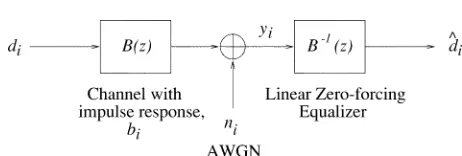
Fig. 1 Block diagram of a simple transmission scheme using a ZF equalizer.
comparatively in Section IV. Finally, our conclusions are offered in Section V.
II. MULTIUSERDETECTION
A. Single-User Channel Equalizers
1) Zero-Forcing Optimization Criterion: The
funda-mental approach of multiuser equalizers accrues from recognizing the fact that the nature of the interference is similar, regardless, whether its source is dispersive multipath propagation or MUI. In other words, the effects of imposing interference on the received signal by a path dispersive channel or by a user system are similar. Hence, we continue our discourse with a rudimentary overview of single-user equalizers in order to pave the way for a more detailed discourse on multiuser equalizers [2], [13]–[15].
The concept of zero-forcing (ZF) channel equalizers can be readily followed using, for example, the approach of [16]. Specifically, the ZF criterion [16] constrains the signal component at the output of the equalizer to be free of intersymbol interference (ISI). More explicitly, this implies that the product of the transfer functions of the dispersive and hence frequency-selective channel and the channel equalizer results in a “frequency-flat” constant, implying that the concatenated equalizer restores the perfect all-pass channel transfer function. This can be formulated as
(1)
(2)
where and are the transforms of the ZF
equalizer and that of the dispersive channel, respectively. The impulse response corresponding to the concatenated system hence becomes a Dirac delta, implying that no ISI is inflicted. More explicitly, the ZF equalizer is constituted by the inverse filter of the channel. Fig. 1 shows the simplified block diagram of the corresponding system.
Upon denoting by and the transforms of the
transmitted signal and the additive noise, respectively, the transform of the received signal can be represented by , where
(3)
The transform of the multiuser equalizer’s output will be
[image:2.612.301.532.16.94.2]Fig. 2 Block diagram of a simple transmission scheme employing a linear MMSE equalizer.
(5)
(6)
From (6), it can be seen that the output signal is free of ISI. However, the noise component is enhanced by the inverse of the transfer function of the channel. This may have a disas-trous effect on the output of the equalizer, in terms of noise amplification in the frequency domain at frequencies where the transfer function of the channel was severely attenuated. Hence a disadvantage of the ZF equalizer is that in an ef-fort to compensate for the effects of the frequency-selec-tive channel and the associated ISI, it substantially enhances the originally white noise spectrum by frequency-selectively amplifying it. This deficiency can be mitigated by invoking the so-called linear minimum mean-square-error (MMSE) equalizer, which is capable of jointly minimizing the effects of noise and interference, rather than amplifying the effects of noise.
2) Minimum Mean-Square-Error Optimization Cri-terion: Linear MMSE equalizers have been considered
in depth, for example, in [16], and a similar approach is followed here. Upon invoking the MMSE criterion [16], the equalizer tap coefficients are calculated in order to minimize the mean-square error (MSE) at the output of the multiuser equalizer, where the MSE is defined as
(7)
where the function indicates the expected value of . Fig. 2 shows the system’s schematic using a linear MMSE equalizer, where is the channel’s transfer function and is the transfer function of the equalizer. The output of the equalizer is given by
(8)
where is the transform of the data bits , is
the transform of the data estimates , and is the transform of the noise samples .
3) Decision Feedback Equalizers: The decision
feed-back equalizer (DFE) [16] can be separated into two components, a feed-forward filter and a feedback filter. The schematic of a general DFE is depicted in Fig. 3. The philosophy of the DFE is twofold. First, it aims for reducing the filter order of the ZFE, since with the aid of (2) and Fig. 1, it becomes plausible that the inverse filter of the channel can only be implemented as an infinite
Fig. 3 Block diagram of a DFE.
impulse response (IIR) filter, requiring a high implemen-tational complexity. Second, provided that there are no transmission errors, the output of the hard-decision detector delivers the transmitted data bits, which can provide valuable explicit training data for the DFE. Hence, a reduced-length feed-forward filter can be used, which, however, does not entirely eliminate the ISI. Instead, the feedback filter uses the data estimates at the output of the data detector in order to subtract the ISI from the output of the feed-forward filter, such that the input signal of the data detector has less ISI, than the signal at the output of the feed-forward filter. If it is assumed that the data estimates fed into the feedback filter are correct, then the DFE is superior to the linear equalizers, since the noise enhancement is reduced. One way of explaining this would be to say that if the data estimates are correct, then the noise has been eliminated, and there is no noise enhancement in the feedback loop. However, if the data estimates are incorrect, these errors will propagate through to future decisions. This problem is known as error propagation.
There are two basic DFEs: the ZF-DFE and the MMSE-DFE. Analogous to its linear counterpart, the coefficients of the feedback filter for the ZF-DFE are calculated so that the ISI at the output of the feed-forward filter is eliminated and the input signal of the data detector is free of ISI [13]. Let us now focus our attention on CDMA multiuser detection equalizers.
B. Multiuser Equalizer Concepts
DS-CDMA systems [17], [18] support a multiplicity of users within the same bandwidth by assigning dif-ferent—typically unique—codes to different users for their communications in order to be able to distinguish their signals from each other. When the transmitted signal is subjected to wireless propagation environments, the signal of different users interfere with each other; hence, CDMA systems are interference limited due to the multiple access interference (MAI) generated by the users transmitting within the same bandwidth simultaneously. A whole range of detectors have been proposed in the literature for miti-gating the effects of MUI, which will be reviewed during our forthcoming discourse.
the users’ spreading codes and their impulse responses with the aid of multiuser detectors (MUDs). RAKE combiners are also capable of exploiting the inherent multipath diversity achievable by CDMA systems, since they essentially consist of multiple matched filters, one assigned for each resolvable path of the multipath channel. The outputs of these matched filters are then coherently combined according to a diversity combining technique, such as maximal ratio combining, equal gain combining, or selection diversity combining [13]. These conventional single-user detectors are inefficient, since the interference is treated as noise and the knowledge of the channel impulse response (CIR) or the spreading sequences of the interferers is not exploited.
To mitigate the problem of MAI, Verdú [20] proposed and analyzed the optimum multiuser detector in the context of asynchronous Gaussian multiple access channels. The op-timum detector evaluates the probability of all the possible bit sequences,5 in order to find the specific sequence that maximizes the correlation metric given by [21]
(9)
where the elements of the vector represent the cross correla-tion (CCL) of the direct-sequence spread, channel-impaired received signal with each of the users’ spreading sequence; the users’ data vector consists of all the synchronously transmitted bits6 of all the users during the current signaling instant; and the matrix is the CCL matrix of the spreading sequences. This optimum detector significantly outperforms the conventional single-user detector, and—in contrast to single-user detectors—it is insensitive to power control errors, which is often termed as being near-far resistant. However, its complexity unfortunately grows exponen-tially in the order of , where is the number of overlapping asynchronous bits considered in the detector’s decision window and is the number of interfering users. To reduce the complexity of the receiver and yet to provide an acceptable BER performance, significant research efforts have been invested in the field of suboptimal CDMA mul-tiuser receivers [21]. Mulmul-tiuser detection exploits the base station’s knowledge of the spreading sequences and that of the estimated CIRs in order to remove the MAI.
These MUDs can be categorized in a number of ways, such as linear versus nonlinear, adaptive versus nonadap-tive algorithms, or burst transmission versus continuous transmission regimes. Excellent summaries of some of these suboptimum detectors can be found in Verdú [21], Prasad [22], Glisic and Vucetic [23], Woodward and Vucatic
5Since Verdú’s MUD aims for identifying the most likelyK bit vector of
theK users of the system, there is a strong analogy between the formulation of this MUD problem and that of the maximum-likelihood sequence esti-mation (MLSE)-based classic channel equalization problem using a classic Viterbi equalizer, which was designed for removing the channel-induced multipath interference, rather than MUI. In this context, we also note that naturally the MLSE solution does not guarantee the minimization of the bit error probability of the individual users.
6The synchronous relationship of the bits is automatically ensured in the
downlink for the base station’s transmission, but requires tight synchroniza-tion in the uplink transmissions of the mobile stasynchroniza-tions as a consequence of their potentially asynchronous internal clock generators and owing to their different propagation distances.
[24], Moshavi [25], Duel-Hallen, Holtzman, and Zvonar, just to mention a few excellent former overviews. Other MAI-mitigating techniques include the employment of interference rejection techniques, which typically impose a lower implementation complexity than MUDs [26].
Adaptive antenna arrays (AAAs) [6] are also capable of mitigating the level of MAI at the receiver by forming a beam in the direction of the wanted user and a null toward the inter-fering users. It is worth noting, however that since the angle of arrival of the multipath components becomes more lim-ited owing to the focused beam of the AAAs, the number of received rays and hence the achievable diversity gain are limited. Therefore, alternative fading countermeasures, such as the employment of adaptive modulation, often become necessary, further advocating the techniques reviewed in this contribution.
Research efforts invested in the area of AAA include, among others, the investigations carried out by Thompson et
al. [27], [28]; Naguib and Paulraj [29]; Godara [30]; as well
as Kohno et al. [31]. However, the area of AAAs is beyond the scope of this article, and the reader is referred to the references cited for further discussions. In the forthcoming section, a brief survey of the suboptimal multiuser receivers will be presented, which constitute an attractive compromise in terms of the achievable performance and the associated complexity.
C. Tree-Search Detection
Several tree-search detection [32]–[34] receivers have been proposed in the literature in order to reduce the com-plexity of the original maximum-likelihood (ML) detection scheme proposed by Verdú [20]. Specifically, Rasmussen et
al. [32] investigated a tree-search detection algorithm, where
a recursive, additive metric was developed in order to reduce the search complexity. Reduced tree-search algorithms, such as the well-known algorithms [35] and algorithms [35] were used by Wei et al. [33] in order to reduce the complexity incurred by the optimum multiuser detector. According to the algorithm, at every node of the trellis search algo-rithm, only surviving paths were retained, depending on certain criteria, such as, for example, the highest metric number of paths. Alternatively, all the paths that were within a fixed threshold compared with the highest metric were retained. At the decision node, the path having the highest metric was chosen as the most likely transmitted sequence. Maximal-ratio combining was also used in conjunction with the reduced tree-search algorithms, and the combining detectors outperformed the “noncombining” detectors. The algorithm was combined with soft-input assisted Viterbi detectors for channel-coded CDMA multiuser detection in the work carried out by Nasiri-Kenari et al. [34]. The recursive tree-search detector generated soft outputs, which were fed into single-user Viterbi channel decoders in order to generate the bit estimates.
MAI, where the wanted signal was separable from the MAI. Having reviewed the two most well-known tree-search type algorithms, we concentrate on the family of intelligent adap-tive detectors in Section III.
D. Linear Receivers
Following the seminal work by Verdú [20], numerous sub-optimum multiuser detectors have been proposed for a va-riety of channels, data modulation schemes and transmis-sion formats [25]. Lupas and Verdú [38] initially suggested a suboptimum linear detector for symbol-synchronous trans-missions and further developed it for asynchronous transmis-sions in a Gaussian channel [39]. This linear detector inverted the CCL matrix seen in (9), which was constructed from the CCLs of the spreading codes of the users; and this re-ceiver was termed the decorrelating detector. It was shown that this decorrelator exhibited the same degree of near-far resistance as the optimum multiuser detector.
A further suboptimum multiuser detector investigated was the MMSE detector, where a biased version of the CCL ma-trix was inverted and invoked in order to optimize the receiver obeying the MMSE criterion. Zvonar and Brady [40] pro-posed a multiuser detector for synchronous CDMA systems designed for a frequency-selective Rayleigh fading channel. Their approach also used a bank of matched filters followed by a so-called whitening filter, but maximal ratio combining was used to combine the resulting signals.
The decorrelating detector of [39] was further developed for differentially encoded coherent multiuser detection in flat fading channels by Zvonar et al. [41]. Zvonar also amalga-mated the decorrelating detector with diversity combining in order to achieve performance improvements in frequency-se-lective fading channels [42]. A multiuser detector jointly per-forming decorrelating CIR estimation and data detection was investigated by Kawahara and Matsumoto [43]. Path-by-path decorrelators were employed for each user in order to obtain the input signals required for CIR estimation, and the CIR es-timates as well as the outputs of a matched filter bank were fed into a decorrelator for demodulating the data.
A variant of this idea was also presented by Hosseinian
et al. [44], where training sequences and a decorrelating
scheme were used for determining the CIR estimate matrix. This matrix was then used in a decorrelating decision feedback scheme for obtaining the data estimates. Juntti
et al. [45] proposed iterative schemes in order to reduce
the complexity. Sung and Chen [46] advocated using a sequential estimator for minimizing the mean square esti-mation error between the received signal and the signal after detection. The CCLs between the users’ spreading codes and the estimates of the channel-impaired received signal of each user were needed to obtain estimates of the transmitted data for each user.
Duel-Hallen [47] proposed a decorrelating decision feed-back detector for removing the MAI from a synchronous system communicating over a Gaussian channel. The out-puts from a bank of filters matched to the spreading codes of the users were passed through a whitening filter. This filter was obtained by decomposing the CCL matrix of the users’
spreading codes with the aid of the Cholesky decomposition [48] technique. The results showed that MAI could be re-moved from each user’s signal successively, assuming that there was no error propagation. However, estimates of the received signal strengths of the users were needed, since the users had to be ranked in order of decreasing signal strengths so that the more reliable estimates were obtained first.
Duel-Hallen’s decorrelating decision feedback detector [47] was improved by Wei and Schlegel [49] with the aid of a suboptimum variant of the Viterbi algorithm, where the most likely paths were retained in the case of merging paths in the Viterbi algorithm. The decorrelating decision feedback detector [47] was also improved with the assistance of soft-decision convolutional coding by Hafeez and Stark [50]. Soft decisions from a Viterbi channel decoder were fed back into the filter for signal cancellation.
Having reviewed the range of linear receivers, we will con-sider the class of joint detection (JD) schemes in Section II-E.
E. Joint Detection
1) Joint Detection Concept: As mentioned before in the
context of single-user channel equalization, the effect of MAI on the desired signal is similar to the impact of multipath propagation-induced ISI on the same signal. Each user in a
user system suffers from MAI due to the other
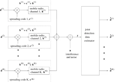
users. This MAI can also be viewed as a single-user signal perturbed by ISI inflicted by paths in a multipath channel. Therefore, the family of classic channel equaliza-tion techniques [13]–[15], [51] originally devised for miti-gating the effects of channel-induced ISI can be invoked for the joint simultaneous detection of the signals received from a multiplicity of users, who impose MUI, rather than ISI. In other words, regardless of whether the source of the inter-ference is multipath propagation-induced ISI or MUI, or in fact both, channel equalizers may be invoked for mitigating their effects. Members of the family of MUDs that are ca-pable of mitigating the effects of both ISI and MUI are often referred to as JD receivers. These JD receivers were devel-oped for burst-based, rather than continuous, CDMA trans-missions. More explicitly, JD receivers were originally de-vised for the uplink by Klein and Baier [52] for the idealistic scenario of synchronous burst transmissions, which is visu-alized with the aid of Fig. 4.
Fig. 4 System model of a synchronous CDMA system on the uplink using JD.
it defines the system’s response, representing the effects of MAI and the mobile channels. Each column in the matrix represents the combined impulse response obtained by convolving the spreading sequence of a user with its
channel impulse response, . This is the
impulse response experienced by a transmitted data symbol. Upon neglecting the effects of the noise, the JD formulation is simply based on inverting the system matrix in order to recover the data vector constituted by the superimposed transmitted information of all the CDMA users. The dimensions of the matrix are
and an example of it can be found in [52] by Klein and Baier, where the list of the symbols used is given as the following.
1) is the total number of users.
2) is the number of data symbols transmitted by each user in one transmission burst.
3) represents the number of chips in each spreading sequence.
4) denotes the length of the wideband CIR, where is assumed to be an integer multiple of the number of chip intervals .
5) indicates the number of multipath components or taps in the wideband CIR.
To introduce compact mathematical expressions, matrix notation will be employed. The transmitted data symbol se-quence of the th user is represented by a vector as
for (10)
where is the user index and is the symbol index. There are data symbols per transmission burst, and each data symbol is generated using an -ary modulation scheme [13].
The chip spreading sequence vector of the th user is expressed as
for (11)
The CIR for the th data symbol of the th user is repre-sented as
for (12)
consisting of complex CIR samples taken at the chip rate of .
The combined impulse response, , due to the spreading sequence and the CIR, is defined by the convolu-tion of and , which is represented as
for
(13)
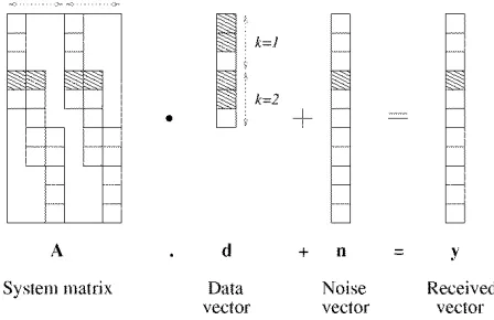
To represent the ISI due to the symbols and the disper-sive combined impulse responses, the discretized received signal, , of user can be expressed as the product of a matrix and its data vector , where
[image:6.612.91.489.30.311.2]Fig. 5 Stylized structure of (14) representing the received signal vector of a wideband channel, whereQ = 4, W = 2, and
N = 3. The column vectors in the matrix A are the combined impulse response vectors,b of (13). A box with an asterisk in it represents a nonzero element, and the remaining notation is as follows:K represents the total number of users, N denotes the number of data symbols transmitted by each user,Q represents the number of chips in each spreading sequence, andW indicates the length of the wideband CIR.
The th element of the received signal vector is
for
(15) Again, the matrix is the so-called system matrix of the th user, and it is constructed from the combined impulse responses of (13). It represents the effect of the combined impulse responses on each data symbol in the data vector . Each column in the matrix indexed by contains the combined impulse response that affects the th symbol of the data vector. However, since the data symbols are spread by the chip spreading sequences, they are transmitted chips apart from each other. Hence, the start of the combined impulse response for each column is offset by rows from the start of in the preceding column. Therefore,
the element in the th row and the th column
of is the th element of the combined impulse response,
, for . All other elements in the
column are zero-valued.
The pictorial representation of (14) is shown in Fig. 5,
where , , and . As can be seen from the
diagram, in each column of the matrix —where a box with an asterisk marks a nonzero element—the vector starts at an offset of rows below its preceding column, except for the first column, which starts at the first row. The total number of elements in the vector is
. The total number of columns in the matrix equals the number of symbols in the data vector, , i.e., . Finally, the received signal vector product, in (14), has a total of elements due to the ISI imposed by the multipath channel, as opposed to elements in a narrow-band channel.
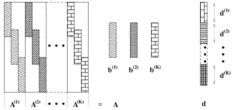
The JD receiver aims for detecting the symbols of all the users jointly by utilizing the information available on the spreading sequences and CIR estimates of all the users. Therefore, as seen in Fig. 6, the data symbols of all users
Fig. 6 The construction of matrixA from the individual system matricesA , seen in Fig. 5, and the data vector d from the concatenation of data vectorsd of allK users.
can be viewed as the transmitted data sequence of a single user, by concatenating all the data sequences. The overall transmitted sequence can be rewritten as
(16)
(17)
where for , ,
and .
The system matrix for the overall system can be con-structed by appending the matrix of each of the users columnwise, whereby
(18)
The construction of matrix from the system matrices of the users is depicted in Fig. 6. Therefore, the discretized received composite signal can be represented in matrix form as
(19)
where is the noise
se-quence, which has a covariance matrix of .
The composite signal vector has elements
for a data burst of length symbols. Upon multiplying the matrix with the vector seen in Fig. 6, we obtain the MAI- and ISI-contaminated received symbols according to (19).
Taken as a whole, the system matrix can be constructed from the combined response vectors of all the users in order to depict the effect of the system’s response on the data vector of (16). The dimensions of the matrix are
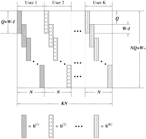
. Fig. 7 shows an example of the matrix for an -bit long data burst. For ease of representation, we assumed that the channel length for each user is the same and that it remains constant throughout the data burst. We have also as-sumed that the channel experiences slow fading and that the fading is almost constant across the data burst. Therefore, the combined response vector for each transmitted symbol of user is represented by , where
[image:7.612.320.550.24.134.2] [image:7.612.91.259.27.167.2]Fig. 7 Stylized structure of the system matrixA, where b , b , and b are column vectors representing the combined impulse responses of users 1, 2, andK, respectively, in (13). The notation is as follows:K represents the total number of users, N denotes the number of data symbols transmitted by each user,Q represents the number of chips in each spreading sequence, and W indicates the length of the wideband CIR.
in the th column of the matrix constitute the combined re-sponse vector that affects the th data symbol in the trans-mitted data vector . Therefore, columns to of ma-trix correspond to symbols to of vector , which are also the data symbols of user . The next columns correspond to the next symbols of data vector , which are the data symbols of user , and so on.
For user , each successive response vector is placed at an offset of rows from the preceding vector, as shown in Fig. 7. For example, the combined response vector in column 1 of matrix is , and it starts at row 1 of the matrix because that column corresponds to the first symbol of user . In column 2, the combined response vector is also , but it is offset from the start of the vector in column 1 by rows. This is because the data symbol corresponding to this matrix column is transmitted chips later. This is
repeated until the columns contain the
com-bined response vectors that affect all the data symbols of user
. The next column of in the matrix
con-tains the combined impulse response vector that affects the data symbol, , which is the first data symbol of user . In this column, the combined response vector for user , , is used, and the vector starts at row 1 of the matrix because it is the first symbol of this user. The response matrix is then placed into columns
of the matrix , with the same offsets for each successive vector, as was carried out for user 1. This process is repeated
for all the other users until the system matrix is completely constructed.
The mathematical representation of matrix in general can be written as
for
otherwise
for (20)
where and .
Fig. 8 shows the stylized structure of (19) for a specific example. In the figure, a system with users is de-picted. Each user transmits symbols per transmission burst, and each symbol is spread with a signature sequence of length chips. The channel for each user has a dis-persion length of chips. The blocked segments in the figure represent the combination of elements that result in the element , which is obtained from (19) by
(21)
(22)
[image:8.612.136.438.24.311.2]Fig. 8 Stylized structure of the matrix equationy = Ad + n for aK = 2-user system. Each user transmits N = 3 symbols per transmission burst, and each symbol is spread with a signature sequence of lengthQ = 3 chips. The channel for each user has a dispersion length ofW = 3 chips.
Fig. 9 Structure of the receiver represented in (23).
composite signal vector in order to determine the trans-mitted data vector . This concept is encapsulated in the fol-lowing set of equations:
(23)
where is a square matrix with dimensions ,
and the matrix is a matrix. These
two matrices determine the type of JD algorithm, as will be-come explicit during our further discourse. The schematic in Fig. 9 shows the receiver structure represented by this equa-tion.
A range of JD schemes designed for uplink commu-nications were proposed by Jung, Blanz, Nasshan, Steil, Baier, and Klein, such as the MMSE block linear equalizer (MMSE-BLE) [53]–[56], the ZF block DFE (ZF-BDFE) [55], [56], and the MMSE block DFE (MMSE-BDFE) [55], [56].
These JD receivers were also combined with coherent receiver antenna diversity techniques [54]–[57] and turbo coding [58], [59] for performance improvement. JD re-ceivers were proposed also for downlink scenarios by Nasshan et al. [60], [61]. CIR estimates were required for the JD receivers, and CIR estimation algorithms were proposed by Steiner and Jung [62] for employment in conjunction with JD. Werner [63] extended the JD receiver by combining ZF-bock linear equalizer and MMSE-BLE techniques with a multistage decision mechanism using soft inputs to a Viterbi decoder.
Having considered the family of JD receivers, which typ-ically exhibit a high complexity, we will now highlight the state of the art in the context of interference cancellation (IC) schemes in Section II-F, which were contrived for main-taining a lower complexity than that exhibited by the JD re-ceivers.
F. Interference Cancellation
IC schemes constitute another variant of multiuser detec-tion, and they can be broadly divided into three categories: parallel IC (PIC), successive IC (SIC), and the hybrids of both. These approaches will be augmented a little further below with reference to Fig. 10 and 11.
1) Parallel Interference Cancellation: To elaborate a little further, Varanasi and Aazhang [64] proposed a multistage detector for an asynchronous system, where the outputs from a matched filter bank were fed into a detector that performed MAI cancellation using a multistage algorithm. At each stage in the detector, the data estimates
of all the other users from the
previous stage were used for reconstructing an estimate of the MAI, and this estimate was then subtracted from the interfered received signal representing the wanted bit. The computational complexity of this detector was linear with respect to the number of users . Fig. 10 depicts the schematic of a single cancellation stage in the PIC receiver. Varanasi further modified the previously described parallel cancellation scheme in order to create a parallel group detection scheme for Gaussian channels [65], and later developed it further for frequency-selective slow Rayleigh fading channels [66]. In this scheme, users were divided into groups, and each group was demodulated in parallel using a group detector. Yoon et al. [67] then extended the applicability of the multistage IC detector to a multipath, slowly fading channel. At each cancellation stage, hard decisions generated by the previous cancellation stage were used for reconstructing the signal of each user and for canceling its contribution from the composite signal. The effects of CIR estimation errors on the performance of the cancellation scheme were also considered. A multiuser receiver that integrated MAI rejection and channel decoding was investigated by Giallorenzi and Wilson [68]. The MAI was canceled via a multistage cancellation scheme, and soft outputs were fed from the Viterbi channel decoder of each user to each stage for improving the performance.
The PIC receiver of Fig. 10 [64] was also modified for employment in multicarrier modulation [69] by Sanada and Nakagawa. Specifically, convolutional coding was used in order to obtain improved estimates of the data for each user at the initial stage, and these estimates were then utilized for IC in the following stages. The employment of convolutional coding improved the performance by 1.5 dB. Latva-aho
et al. [70] enhanced the performance of the PIC receiver
by feeding back CIR estimates to the signal reconstruction stage of the multistage receiver seen in Fig. 10 and proposed an algorithm for mitigating error propagation. Dahlhaus et
al. [71] combined multistage detection with CIR estimation
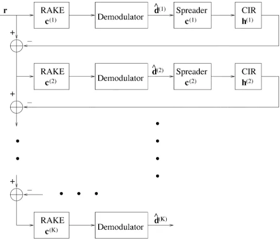
[image:9.612.60.284.33.178.2] [image:9.612.78.265.240.277.2]Fig. 10 Schematic of a single cancellation stage for userk in the PIC receiver for K users. The data estimates ^d ; . . . ; ^d of the other(K 0 1) users were obtained from the previous cancellation stage, and the received signal of each user other than thek-th one is reconstructed and canceled from the received signalr.
Fig. 11 Schematic of the SIC receiver forK users. The users’ signals have been ranked, where user 1’s signal was received at the highest power, while userK’s signal at the lowest power. In the order of ranking, the data estimates of each user are obtained, and the received signal of each user is reconstructed and canceled from the received composite signalr.
the weights were increased based on the assumption that the estimates became increasingly accurate.
2) Successive Interference Cancellation: We will now
consider the family of reduced-complexity SIC receivers. A simple SIC scheme was analyzed by Patel and Holtzman [73]. The received signals were ranked according to their correlation values, which were obtained by utilizing the correlations between the received signal and the spreading codes of the users. The transmitted information of the strongest user was estimated, enabling the transmitted signal to be reconstructed with the aid of the spreader as well as
[image:10.612.144.432.283.530.2]with the RAKE correlator [73]. Again, Fig. 11 shows the schematic of the SIC receiver. Soong and Krzymien [74] extended the SIC receiver by using reference symbols in order to aid the CIR estimation. The performance of the receiver was investigated in both flat and frequency-selective Rayleigh fading channels, as well as in multicell scenarios. A soft decision-based adaptive SIC scheme was proposed by Hui and Letaief [75], where soft decisions were used in the cancellation stage. More explicitly, if the decision statistics did not satisfy a certain threshold, no data estimation was carried out for that particular data bit in order to reduce the effects of error propagation. Finally, in [76], it was shown by Viterbi that with the aid of low-rate orthogonal convolutional codes and with the advent of an efficient SIC scheme employing coordinated processing of a large number of users, the achievable data rate of all users may approach the Shannon capacity of the Gaussian channel.
3) Hybrid Interference Cancellation: Hybrid SIC and
PIC schemes were proposed, for example, by Li and Steele [77] and by Oon et al. [78], where SIC was first performed on the received signal, followed by a multistage PIC ar-rangement. This work was then extended to an adaptive hybrid scheme for flat Rayleigh fading channels [79]. In this scheme, successive cancellation was performed for a fraction of the users, while the remaining users’ signals were processed via a parallel cancellation stage. Finally, multistage parallel cancellation was invoked. The number of serial and parallel cancellations performed was varied adaptively according to the BER estimates. Sawahashi
et al. [80] proposed a pilot symbol-assisted multistage
hybrid successive-parallel cancellation scheme. At each stage, data estimation was carried out successively for all the users, commencing with the user having the strongest signal and ending with the weakest signal. For each user, the interference inflicted by the other users was regenerated using the estimates of the current stage for the stronger users and the estimates of the previous stage for the weaker users. CIR estimates were obtained for each user by employing pilot symbols and a recursive estimation algorithm. Another hybrid SIC and PIC receiver was proposed by Sun et al. [81], where the users to be detected were split into a number of groups. Within each group, PIC was performed on the signals of these users belonging to the group. Between the separate groups, SIC was employed. This had the advantage of a reduced delay and improved performance compared with that of the SIC receiver. A further variant of the hybrid cancellation scheme was constituted by the combination of MMSE detectors with SIC receivers, as proposed by Cho and Lee [82]. Single-user MMSE detectors were used to obtain estimates of the data symbols, which were then fed back into the SIC stages. An adaptive IC scheme was investigated by Agashe and Woerner [83] for a multicellular scenario, where IC was performed for both in-cell interferers and out-of-cell interferers, even though the detection of the out-of-cell interferers is not required at the base station considered. It was shown that canceling the estimated inter-ference from users having weak signals actually degraded the performance, since the estimates were inaccurate. The
adaptive scheme exercised IC in a discriminating manner, using only the data estimates of users having strong received signals. Therefore, signal power estimation was needed, and the threshold for signal cancellation was adapted ac-cordingly. We will now focus our attention on the family of tree-type detection techniques.
G. Adaptive Multiuser Detection
In all the multiuser receiver schemes discussed earlier, the required parameters—except for the transmitted data estimates—were assumed to be known at the receiver. To remove this constraint while reducing the complexity, adaptive receiver structures have been proposed [84]. An excellent summary of these adaptive receivers has been provided by Woodward and Vucetic [24]. Several adaptive algorithms have been introduced for approximating the performance of the MMSE receivers, such as the least mean squares (LMS) [51] algorithm, the recursive least squares (RLS) algorithm [51], and the Kalman filter [51]. Xie et al. [85] showed that the adaptive MMSE approach could be applied to multiuser receiver structures with a concomitant reduction in complexity. In the adaptive receivers employed for asynchronous transmission by Rapajic and Vucetic [84], training sequences were invoked in order to obtain the esti-mates of the parameters required. Lim et al. [86] introduced a multiuser receiver for an asynchronous flat-fading channel based on the Kalman filter, which compared favorably with the finite impulse response MMSE detector. An adaptive decision feedback-based JD scheme was investigated by Seite and Tardivel [87], where the LMS algorithm was used to update the filter coefficients in order to minimize the MSE of the data estimates. New adaptive filter architectures for downlink DS-CDMA receivers were suggested by Spangenberg et al. [88], where an adaptive algorithm was employed in order to estimate the CIR, and this estimated CIR was then used by a channel equalizer. The output of the channel equalizer was finally processed by a fixed multiuser detector in order to provide the data estimates of the desired user.
H. Blind Detection
based on maximizing the signal-to-interference-plus-noise ratio (SINR) at the output of each RAKE finger.
Xie et al. [91] proposed an approximate MLSE solution known as the per-survivor processing (PSP) type algorithm, which combined a tree-search algorithm for data detection with the RLS adaptive algorithm used for channel amplitude and phase estimation. The PSP algorithm was first proposed by Seshadri [92]; as well as by Raheli et al. [93], [94] for blind equalization in single-user ISI-contaminated channels. Xie et al. extended their own earlier work [91] to include the estimation of user delays along with channel and data estimation [95].
Iltis and Mailaender [96] combined the PSP algorithm with the Kalman filter in order to adaptively estimate the amplitudes and delays of the CDMA users. In other blind detection schemes, Mitra and Poor compared the application of neural networks and LMS filters for obtaining data estimates of the CDMA users [97]. In contrast to other multiuser detectors, which required the knowledge of the spreading codes of all the users, only the spreading code of the desired user was needed for this adaptive receiver [97]. An adaptive decorrelating detector was also developed by Mitra and Poor [98], which was used to determine the spreading code of a new user entering the system.
In Wang and Poor [99], blind equalization was combined with multiuser detection for slowly fading channels. Only the spreading sequence of the desired user was needed, and a ZF as well as an MMSE detector were developed for data de-tection. As a further solution, a so-called subspace approach to blind multiuser detection was also proposed by Wang and Poor [100], where only the spreading sequence and the delay of the desired user were known at the receiver. Based on this knowledge, a blind subspace tracking algorithm was devel-oped for estimating the data of the desired user. Further blind adaptive algorithms were developed by Honig et al. [101], Mandayam and Aazhang [102], as well as by Ulukus and Yates [103]. In [101], the applicability of two adaptive algo-rithms to the multiuser detection problem was investigated, namely that of the stochastic gradient algorithm and the least squares algorithm, while in [103], an adaptive detector that converged to the solution provided by the decorrelator was analyzed.
The employment of the Kalman filter for adaptive data, CIR, and delay estimation was carried out by Lim and Rasmussen [104]. They demonstrated that the Kalman filter gave a good performance and exhibited a high grade of flexibility. However, the Kalman filter required reliable initial delay estimates in order to initialize the algorithm. Miguez and Castedo [105] modified the well-known con-stant modulus approach [106], [107] to blind equalization for ISI-contaminated channels in the context of MUI suppression. Fukawa and Suzuki [108] proposed an orthog-onalizing matched filtering detector, which consisted of a bank of despreading filters and a signal combiner. One of the despreading filters was matched to the desired spreading sequence, while the other despreading sequences were arbi-trarily chosen such that the impulse responses of the filters were linearly independent of each other. The filter outputs
were adaptively weighted in the complex domain under the constraint that the average output power of the combiner was minimized. In another design, an iterative scheme used to maximize the so-called log-likelihood function was the basis of the research by Fawer and Aazhang [109]. RAKE correlators were employed for exploiting the multipath diversity, and the outputs of the correlators were fed to an iterative scheme for joint CIR estimation and data detection using the Gauss–Seidel [110] algorithm.
I. Hybrid and Novel Multiuser Receivers
Several hybrid multiuser receiver structures have also been proposed recently [111]–[114]. Bar-Ness [111] advocated the hybrid multiuser detector that consisted of a decorrelator for detecting asynchronous users, followed by a data com-biner maximizing the SNR, an adaptive canceler, and another data combiner. The decorrelator matrix was adaptively deter-mined.
A novel multiuser CDMA receiver based on genetic algorithms (GAs) was considered by Yen et al. [112], where the transmitted symbols and the channel parameters of all the users were jointly estimated. The ML receiver of synchronous CDMA systems exhibits a computational com-plexity that is exponentially increasing with the number of users, since at each signaling instant, the corresponding data bit of all users has to be determined. Hence, the employment of ML detection invoking an exhaustive search is not a practical approach. GAs have been widely used for solving complex optimization problems in engineering, since they typically constitute an attractive compromise in performance versus complexity terms. Using the approach of [112], GAs can be invoked in order to jointly estimate the users’ channel parameters as well as the transmitted bit vector of all the users at the current signaling instant with the aid of a bank of matched filters at the receiver. It was shown in [112] that GA-based multiuser detectors can approach the single-user BER performance at a significantly lower complexity than that of the optimum ML multiuser detector without the employment of training sequences for channel estimation.
the bits between two parent or candidate data vectors were exchanged according to a random crossover mask and a certain exchange probability. Finally, the so-called mutation was performed, where the value of a bit in the data vector was flipped according to a certain mutation probability. To prevent the loss of “high-fitness” parent sequences during the process of evolution of the estimated user data vectors, the “highest merit” estimated user data vector that was initially excluded from the pool of parent vectors in creating a new generation of candidate data vectors was then used to replace the “lowest merit” offspring.
Neural network-type multiuser equalizers have also been proposed as CDMA receivers [115], [116]. Specifically, Tanner and Cruickshank proposed a nonlinear receiver that exploited neural-network structures and employed pattern recognition techniques for data detection [115]. This work [115] was extended to a reduced complexity neural-network receiver for the downlink scenario [116]. The advantage of the neural network-based receivers is that they are capable of learning the optimum partitioning rules in the signal constellation space, even when the received interference-contaminated constellation points are linearly nonseparable. In this scenario, linear receivers would exhibit a residual BER even in the absence of channel noise.
Other novel techniques employed for mitigating the multipath fading effects inflicted on multiple users include joint transmitter-receiver optimization proposed by Jang
et al. [113] and Vojˇcic´ and Jang [114]. In these schemes,
transmitter precoding was carried out, such that the mean squared errors of the signals at all the receivers were mini-mized. This required the knowledge of the CIRs of all the users, and the assumption was made that the channel fading was sufficiently slow, such that CIR prediction could be employed reliably by the transmitter.
Recently, there has been significant interest in iterative de-tection schemes, where channel coding was exploited in con-junction with multiuser detection in order to obtain a high BER performance. The spreading of the data and the con-volutional channel coding was viewed as a serially concate-nated code structure, where the CDMA channel was viewed as the inner code and the single user convolutional codes con-stituted the outer codes. After processing the received signal in a bank of matched filters (MFs), the MF outputs were pro-cessed using a so-called turbo-style iterative decoding (aka TEQ) [3], [117] process. In this process, a multiuser decoder was used to produce bit confidence measures, which were used as soft inputs of the single-user channel decoders. These single-user decoders then provided similar confidence met-rics, which were fed back to the multiuser detector. This it-erative process continued, until no further performance im-provement was recorded.
Giallorenzi and Wilson [118] presented the ML solution for the asynchronous CDMA channel, where the user data was encoded with the aid of convolutional codes. Near-single-user performance was achieved for the two-user case in conjunction with fixed length spreading codes. The decoder was implemented using the Viterbi channel decoding algorithm, where the number of states increased
exponentially with the product of the number of users and the constraint length of the convolutional codes. Later, a sub-optimal modification of this technique was proposed [68], where the MAI was canceled via multistage cancellation and the soft outputs of the Viterbi algorithm were supplied to each stage of the multistage canceller for improving the performance. Following this, several iterative multiuser detection schemes employing channel-coded signals have been presented [119]–[124]. For example, Alexander et al. [121], [123] proposed the multiuser maximum a posteriori (MAP) detectors for the decoding of the inner CDMA channel code and invoked single-user MAP decoders for the outer convolutional code. A reduced complexity solution employing the -algorithm [35] was also suggested, which resulted in a complexity that increased linearly—rather than exponentially, as in [118]—with the number of users [122]. Wang and Poor [124] employed a soft-output multiuser detector for the inner channel code, which combined soft IC and instantaneous linear MMSE filtering, in order to reduce the complexity. These iterative receiver structures showed considerable promise, and near-single-user performance was achieved at high SNRs.
Having considered the family of various CDMA detectors, let us now turn our attention to a suite of adaptive-rate CDMA schemes.
III. ADAPTIVE-RATECDMA SCHEMES
transmission have been proposed in the literature. Next, we will briefly discuss some of the current research on multi-rate transmission schemes, before focusing our attention on BbB-adaptive systems.
Ottosson and Svensson compared various multirate sys-tems [128], including multiple spreading factor (SF)-based, multicode, and multilevel modulation schemes. According to the multicode philosophy, the SF is kept constant for all users, but multiple spreading codes transmitted simultane-ously are assigned to users requiring higher bit rates. In this case—unless the spreading codes’s perfect orthogonality is retained after transmission over the channel—the multiple codes of a particular user interfere with each other. This in-evitebly reduces the system’s performance.
Multiple data rates can also be supported by a variable SF scheme, where the chip rate is kept constant, but the data rates are varied, thereby effectively changing the SF of the spreading codes assigned to the users; at a fixed chip rate, the lower the SF, the higher the supported data rate. Performance comparisons for both of these schemes have been carried out by Ottosson and Svensson [128], as well as by Ramakr-ishna and Holtzman [129], demonstrating that both schemes achieved a similar performance. Adachi et al. [130] and Dohi
et al. [131] proposed the employment of multicode CDMA in
conjunction with pilot symbol-assisted channel estimation, RAKE reception, and antenna diversity for providing multi-rate capabilities. The employment of multilevel modulation schemes was also investigated by Ottosson and Svensson [128], where higher rate users were assigned higher order modulation modes, transmitting several BPS. However, it was concluded that the performance experienced by users re-quiring higher rates was significantly worse than that experi-enced by the lower rate users. The use of -ary orthogonal modulation in providing variable-rate transmission was in-vestigated by Schotten et al. [132]. According to this method, each user was assigned an orthogonal sequence set, where the number of sequences in the set was dependent on the data rate required—the higher the rate required, the larger the sequence set. Each sequence in the set was mapped to a particular combination of bits to be trans-mitted. The -ary sequence was then spread with the aid of a spreading code of a constant SF before transmission. It was found that the performance of the system depended not only on the MAI, but also on the Hamming distance between the sequences in the -ary sequence set.
Saquib and Yates [133] investigated the employment of the decorrelating detector in conjunction with the mul-tiple-SF scheme and proposed a modified decorrelating detector, which utilized soft decisions and maximal ratio combining in order to detect the bits of the different-rate users. Multirate transmission schemes involving IC re-ceivers have previously been investigated by, among others, Johansson and Svensson [134], [135], as well as by Juntti [136]. Typically, multiple users transmitting at different bit rates are supported in the same CDMA system invoking multiple codes or different spreading factors. SIC schemes and multistage cancellation schemes were used at the receiver for mitigating the MAI [134]–[136], where the
bit rate of the users was dictated by the user requirements. The performance comparison of various multiuser detectors in the context of a multiple-SF transmission scheme was presented for example by Juntti [136], where the detectors compared were the decorrelator, the PIC receiver, and the so-called group serial IC (GSIC) receiver. It was concluded that the GSIC and the decorrelator performed better than the PIC receiver, but all the IC schemes including the GSIC, exhibited an error floor at high SNRs due to error propagation.
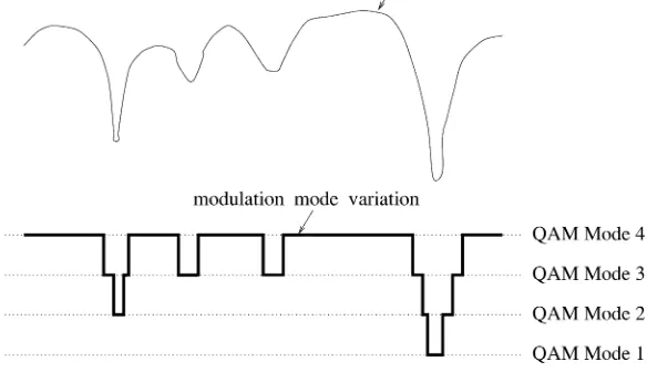
Fig. 12 Basic concept of a four-mode AQAM transmission in a narrow-band channel. The variation of the modulation mode follows the fading variation of the channel over time.
Adachi [141], where the fluctuating transmission rate was mapped to discontinuous transmission in order to reduce the interference inflicted on the other users when there was no transmission. The transmission rate was detected blindly at the receiver with the help of cyclic redundancy check decoding and RAKE receivers were employed for coherent reception, where pilot-symbol-assisted channel estimation was performed.
The information rate can also be varied in accordance with the channel quality, as will be demonstrated shortly. However, in comparison to conventional power control techniques—which again, may disadvantage other users in an effort to maintain the quality of the links considered—the proposed technique does not disadvantage other users and increases the network capacity [142]. The instantaneous channel quality can be estimated at the receiver, and the chosen information rate can then be communicated to the transmitter via explicit signaling in a so-called closed-loop controlled scheme. Conversely, in an open-loop scheme—provided that the downlink and uplink channels exhibit a similar quality—the information rate for the down-link transmission can be chosen according to the channel quality estimate related to the uplink and vice versa. The validity of the previously described channel reciprocity issues in time division duplex (TDD)–CDMA systems have been investigated by Miya et al. [143], Kato et al. [144], and Jeong et al. [145].
In Section IV, two different methods of varying the in-formation rate are considered: namely, the AQAM scheme and the VSF scheme. AQAM is an adaptive-rate technique, whereby the data modulation mode is chosen according to some criterion related to the channel quality. On the other hand, in VSF transmission, the information rate is varied by adapting the spreading factor of the CDMA codes used, while keeping the chip rate constant. A range of other de-sign issues of adaptive CDMA can be found, for example, in
[2], [4], [7], [139], [146]–[148]. Further elaborations on the AQAM/CDMA and VSF/CDMA methods will be given in Sections IV-A–F.
IV. BURST-BY-BURSTAQAM/CDMA
A. BbB AQAM/CDMA Philosophy
BbB AQAM [13] is a technique that attempts to increase the average throughput of the system by switching between modulation modes depending on the instantaneous state or quality of the channel. When the channel quality is favorable, a modulation mode having a high number of con-stellation points is used to transmit as many BPS as possible in order to increase the throughput. Conversely, when the channel is hostile, the modulation mode is switched to using a low number of constellation points in order to reduce the error probability and to maintain a certain adjustable target BER. Fig. 12 shows the stylized quality variation of the fading channel and the switching of the modulation modes in a four-mode AQAM system, where both the BER and the throughput increase, when switching from Mode 1 to 4.
(a) (b)
[image:16.612.46.534.20.221.2](c)
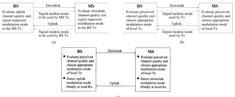
Fig. 13 Three different methods of modulation mode signaling for the adaptive schemes, where BS represents the Base Station, MS denotes the Mobile Station, the transmitter is represented by Tx, and the receiver is denoted by Rx.
burst, provided that the uplink and downlink channel quality can be considered similar. Then, the transmitter explicitly informs the remote receiver as to the modem mode used in the burst, and modulation mode detection would then be performed on this basis at the receiver. This scheme performs most successfully in situations where the channel fading varies slowly in comparison to the burst transmission rate. Channel quality estimation is inherently less accurate in a fast-fading channel, and this lag in the quality estimation renders the choice of modulation mode less appropriate for the channel. Another approach to this issue would be for the receiver to detect the modulation mode used blindly [149], [150], as shown in Fig. 13(c).
B. Channel Quality Metrics
As stated earlier, a metric corresponding to the near-in-stantaneous channel quality is required in order to adapt the AQAM modes. Some examples of these metrics include the carrier-to-interference ratio (C/I) of the channel [151], the SNR of the channel [13], [126], the received signal strength indicator’s (RSSI) output [152], the MSE at the output of the receiver’s channel equalizer, and the BER of the system [153]. The most accurate metric is the BER of the system, since this metric corresponds directly to the system’s per-formance, irrespective of the actual source of the channel impairment. However, the BER is dependent on the AQAM mode employed, and cannot be estimated directly for most receivers. For a system that incorporates channel coding, such as turbo coding [154], the so-called log-likelihood ratios (LLR)—which indicate the ratio of the probabilities of the estimated bit taking its two possible values—at the input and output of the turbo decoder can also be employed as the adaptation metric. AQAM systems were first proposed for narrow-band channels, and the research in this field includes work published by Webb and Steele [13], [126], Sampei et al. [151], Goldsmith and Chua [155], as well
as Torrance et al. [156]. Webb et al. [13], [126] employed Star quadrature amplitude modulation (QAM) [13], and the channel quality was determined by measuring the received signal strength and the near-instantaneous BER. Sampei
et al. [151] switched the modulation modes by estimating
the signal to cochannel interference ratio and the expected delay spread of the channel. This work has been extended to wideband channels by Wong et al. [157], where the received signal also suffers from ISI in addition to amplitude and phase distortions due to the fading channel. In wideband AQAM systems, the channel SNR, the C/I, or RSSI metrics cannot be readily estimated or predicted, among other factors due to the multipath nature of the channel or as a result of the so-called birth-death processes associated with the sudden appearance or disappearance of communicating users. Additionally, the previously described simple metrics do not provide accurate measures of the system performance at the output of the receiver employed, since the effects of the dispersive CIR are not considered in the estimation of these metrics. Wong et al. [158] proposed a combined adaptive modulation and equalization scheme, where a Kalman-filtered DFE was used to mitigate the effects of ISI inflicted on the signal. The CIR estimate was used to calculate the signal-to-residual-ISI-plus-noise ratio (SRNR) at the output of the channel equalizer, and this SRNR value was used to switch the modulation modes. This was a more appropriate switching parameter than the received signal level, since it was a reliable indicator of the performance that could be achieved after equalization.
In AQAM/CDMA systems, the SRNR— , for
—at the output of the multiuser receiver is estimated for all the users by employing the estimated CIRs and spreading sequences of all the users [159]. After is calculated, the modulation mode is chosen accordingly and communicated to the transmitter. Let us designate the choice of modulation modes by , where the total number of
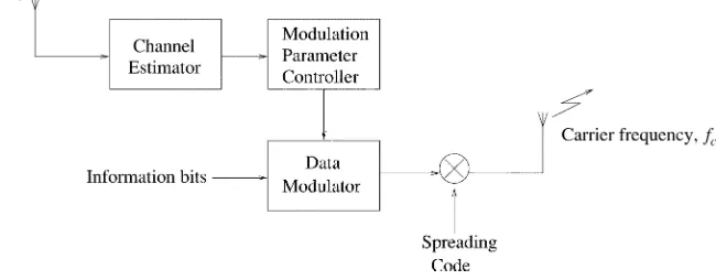
Fig. 14 The schematic of the transmitter of an AQAM/CDMA system. In this transmitter, a TDD transmission scheme is assumed. Channel estimates are obtained by assuming close correlation between the uplink and downlink channels, which are used to measure the quality of the channel. This quality measure is passed to the modulation parameter controller, which selects the modulation mode according to the thresholds set. The data bits are mapped to QAM symbols according to the chosen modulation mode, spread with the spreading code, and modulated on to the carrier.
Table 1
The General Rules Employed for Switching the Modulation Modes in an AQAM System
The choices of modulation modes are denoted by , where the total number of modulation modes is and
. The modulation modes with the lowest and highest number of constellation points are and , re-spectively. The SINR at the output of the multiuser receiver is represented by and the values rep-resent the switching thresholds, where
.
mode having the lowest number of modulation constellation points is , and the one with the highest is . The rules used to switch the modulation modes are tabulated in Table 1, where is the SINR of the th user at the output of the multiuser receiver, and the values represent the
switching thresholds, where .
The schematic of the transmitter is shown in Fig. 14. The data bits are mapped to their respective symbols according to the modulation mode chosen. The QAM symbols are then spread with the spreading code assigned to the user, modu-lated on to the carrier, and transmitted. At the output of the multiuser receiver, the data estimates are demodulated ac-cording to the modulation mode used for transmission. Let us now embark on the comparative performance study of var-ious AQAM/CDMA schemes in Section IV-C.
C. Comparison of JD, SIC, and PIC CDMA Receivers for AQAM Transmission
In this section, a comparative performance study of JD-CDMA, SIC-CDMA, and PIC-CDMA systems is pro-vided in the context of AQAM transmissions. The switching criterion employed was the SINR at the output of the
Table 2
Simulation Parameters for the JD, SIC, and PIC AQAM-CDMA Systems
Fig. 15 Normalized channel impulse response for the COST 207 [160] seven-path Bad Urban channel.
[image:17.612.97.253.279.378.2](a)
(b)
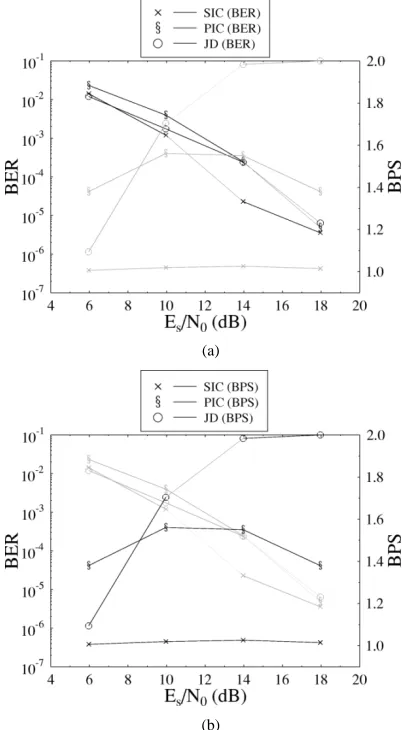
Fig. 16 Performance comparison of the JD, SIC, and PIC CDMA receivers for twin-mode (BPSK, 4-QAM) AQAM transmission and
K = 8 users over the Bad Urban channel of Fig. 15. The rest of the
simulation parameters are tabulated in Table 2.
system than in GSM, we nonetheless used the COST 207 models, since these are widely used in the community. The CIR profile of the COST 207 [160] Bad Urban channel is shown in Fig. 15.
Fig. 16 compares the performance of the JD receiver, the SIC receiver, and the PIC receiver for a twin-mode, eight-user AQAM-CDMA system, switching between BPSK and 4-QAM. Here, the BER performance of all three receivers was kept as similar as possible, and the performance compar-ison was evaluated on the basis of their BPS throughput. The BPS throughput of the JD was the highest, where
approxi-mately 1.9 BPS was achieved at dB. The PIC
receiver outperformed the SIC receiver in BPS-throughput terms, where the BPS throughput of the PIC receiver was
approximately 1.55 BPS at dB compared with
[image:18.612.54.255.28.393.2] [image:18.612.319.518.29.224.2]the approximately 1.02 BPS achieved by the SIC receiver. The two IC receivers suffered from MAI and were unable to match the performance of the JD receiver. The PIC receiver outperformed the SIC receiver, since the received signal powers of all the users were similar on average; hence—as expected—the PIC receiver achieved a higher degree of IC than the SIC receiver.
Fig. 17 BER and BPS performance comparisons for triple-mode JD, SIC, and PIC AQAM-CDMA schemes supportingK = 8 users over the Bad Urban channel of Fig. 15. The modulation mode was chosen to be BPSK, 4-QAM, or 16-QAM. The rest of the simulation parameters are tabulated in Table 2.
The previous performance comparisons between the three multiuser receivers were then extended to triple-mode AQAM systems—switching between BPSK, 4-QAM, and
16-QAM—that supported users, as portrayed in
Fig. 17. For these systems, we can observe from the results that both the PIC and SIC receivers were unable to match the BPS performance of the JD receiver, when the multiuser receivers achieved similar BERs. This was because the increase in the number of users aggravated the MAI, thus degrading the ability of the RAKE receivers to provide reliable data estimates for IC. Here again, the PIC receiver outperformed the SIC receiver in BPS-throughput terms.
Let us now provide performance comparisons for the JD, SIC, and PIC receivers in the context of VSF-CDMA schemes, rather than AQAM-CDMA.
D. VSF-CDMA
Multirate transmission systems using spreading sequences having different processing gains have been proposed in the literature among others by Adachi et al. [161]; Ottosson and Svensson [128]; Ramakrishna and Holtzman [129]; Saquib and Yates [133]; as well as by Johansson and Svensson [134]. In the FRAMES FMA2 Wideband CDMA proposal for UMTS [162], different bit rates are accommodated by supporting VSF- [161] and multicode-based operation. In this section, we discuss the employment of VSF codes in adaptive-rate CDMA systems, where the chip rate of the CDMA users is kept constant throughout the trans-mission, while the bit rate is varied by using spreading codes exhibiting different spreading factors over the course of transmission. For example, by keeping the chip rate constant, the number of bits transmitted in the same period upon using a spreading code of length is twice the number of bits transmitted upon using a spreading code of