Part No. 166-024-162 Rev. A April 1997
Hardware Installation Guide
Remote Access
Concentrator
statements, configurations, technical data, and recommendations in this document are believed to be accurate and reliable, but are presented without express or implied warranty. Users must take full responsibility for their applications of any products specified in this document. The information in this document is proprietary to Bay Networks, Inc.
The software described in this document is furnished under a license agreement and may only be used in accordance with the terms of that license.
Restricted Rights Legend
Use, duplication, or disclosure by the United States Government is subject to restrictions as set forth in subparagraph (c)(1)(ii) of the Rights in Technical Data and Computer Software clause at DFARS 252.227-7013.
Notice for All Other Executive Agencies
Notwithstanding any other license agreement that may pertain to, or accompany the delivery of, this computer software, the rights of the United States Government regarding its use, reproduction, and disclosure are as set forth in the Commercial Computer Software-Restricted Rights clause at FAR 52.227-19.
Trademarks of Bay Networks, Inc.
Annex, Remote Annex, Annex Manager, Remote Annex 2000, Remote Annex 4000, Remote Annex 6100, Remote Annex 6300, Remote Annex 5390/Async, Remote Annex 5391/CT1, Remote Annex 5393/PRI, BayStack Remote Annex 2000 Server, Quick2Config, Bay Networks, Bay Networks Press, and the Bay Networks logo are trademarks of Bay Networks, Inc.
Third Party Trademarks
All other trademarks and registered trademarks are the property of their respective owners.
Statement of Conditions
In the interest of improving internal design, operational function, and/or reliability, Bay Networks, Inc. reserves the right to make changes to the products described in this document without notice.
Bay Networks, Inc. does not assume any liability that may occur due to the use or application of the product(s) or circuit layout(s) described herein.
(2) this device must accept any interference received, including interference that may cause undesired operation.
Warning: Changes or modifications to this unit not expressly approved by the party responsible for compliance could void the user’s authority to operate the equipment.
Note: This equipment has been tested and found to comply with the limits for a Class A digital device, pursuant to Part 15 of the FCC Rules. These limits are designed to provide reasonable protection against harmful interference when the equipment is operated in a commercial environment. This equipment generates, uses, and can radiate radio frequency energy and, if not installed and used in accordance with the instruction manual, may cause harmful interference to radio communications. Operation of this equipment in a residential area is likely to cause harmful interference in which case the user will be required to correct the interference at his own expense.
Declaration of Conformance
This is to certify that the Bay Networks products in this book are shielded against the generation of radio interference in accordance with the application of Council Directive 89/336/EEC, Article 4a. Conformity is declared by the application of EN 55 022: 1987 Class A (CISPR 22: 1985/BS 6527: 1988), EN 50082-1, and EN 60950.
Industry Canada Notice
Canadian Department of Communications Radio Interference Regulations
This digital apparatus does not exceed the Class A limits for radio-noise emissions from digital apparatus set out in the Radio Interference Regulations of the Canadian Department of Communications.
Réglement sur le brouillage radioélectrique du ministère des Communications
Les present appareil numerique n’emet pas de bruits radioelectriques depassant les limites applicables aux appareils numeriques de la classe A prescrites dans le Reglement sur le brouillage radioelectrique edicte par le ministere des
Voluntary Control Council for Interference (VCCI) Statement
This equipment is in the 1st category (information equipment to be used in commercial
and/or industrial areas) and conforms to the standards set by the Voluntary Council for Interference by Data Processing Equipment and Electronic Office Machines that are aimed at preventing radio interference in commercial and/or industrial areas.
equipment will operate to the user’s satisfaction.
Before installing this equipment, users should ensure that it is permissible to be connected to the facilities of the local telecommunications company. The equipment must also be installed using an acceptable method of connection. In some cases, the company’s inside wiring associated with a single line individual service may be extended by means of a certified connector assembly (telephone extension cord). The customer should be aware that compliance with the above conditions may not prevent degradation of service in some situations.
Repair to certified equipment should be made by an authorized Canadian maintenance facility designated by the supplier. Any repairs or alterations made by the user to this equipment, or equipment malfunctions, may give the telecommunications company cause to request the user to disconnect the equipment.
Users should ensure for their own protection that the electrical ground connections of the power utility, telephone lines, and internal metallic water pipe system, if present, are connected together. This precaution may be particularly important in rural areas.
standard plugs and jacks.
2 Before connecting your unit, you must inform the local telephone company of the following information:
3 If the unit appears to be malfunctioning, it should be disconnected from the telephone lines until you learn if your equipment or the telephone line is the source of the trouble. If your equipment needs repair, it should not be reconnected until it is repaired.
4 This device has been designed to prevent harm to the network. If the telephone company finds that the equipment is exceeding tolerable parameters, the telephone company can temporarily disconnect service, although they will attempt to give you advance notice if possible.
5 Under the FCC Rules, no customer is authorized to repair this
equipment. This restriction applies regardless of whether the equipment is in or out of warranty.
6 If the telephone company alters their equipment in a manner that will affect use of this device, they must give you advance warning so as to give you the opportunity for uninterrupted service. You will be advised of your right to file a complaint with the FCC.
7 In the event of equipment malfunction, all repairs should be performed by our Company or an authorized agent. It is the responsibility of users requiring service to report the need for service to our Company or one of our authorized agents. For more details, seeTechnical Support and Online Services on page xix.
Port ID REN/SOC FIC USOC
WAN 1, WAN 2 6.0Y 04DU9-BN 04DU9-DN 04DU9-1KN 04DU9-1ZN 04DU9-1SN
About this Guide . . . xv
Printing Conventions. . . xvi
Related Documents . . . xvii
Technical Support and Online Services Bay Networks Customer Service . . . xix
Bay Networks Information Services . . . xxi
World Wide Web . . . .xxi
Customer Service FTP . . . xxii
Support Source CD . . . xxii
CompuServe . . . xxii
InfoFACTS . . . xxiii
How to Get Help . . . .xxiv
Chapter 1 Introduction Model 5399 Description . . . 3
Module Features . . . 4
System 5000 Common Management Bus . . . 5
System 5000 Backplane Ethernet Segment Banks . . . 6
System 5000 Service Port Management . . . 6
Firmware and Software. . . 7
Front Panel . . . 8
Front Panel Components . . . 10
Physical Characteristics . . . 13
Chapter 2 Installing the Model 5399 Remote Access Concentrator Module Before you Begin . . . 1
Installing the Model 5399 Remote Access Concentrator . . . 3
Preparing for Hardware Installation. . . 3
Setting the Backplane Ethernet Segment . . . 3
Installing the Module into the Hub . . . 6
Testing the Installation . . . 10
LED Indicators. . . 11
Connecting a WAN Interface . . . 12
Connecting a Service Port Terminal . . . 14
Connecting the Terminal . . . 15
Initial Setup and Using the ROM Monitor . . . 17
Remote Access Concentrator Parameters . . . 18
Initializing the Remote Access Concentrator . . . 19
Booting the Remote Access Concentrator . . . 23
Auto-initializing the IP Address Parameters . . . 23
Self-booting the Remote Access Concentrator. . . 31
Booting from a Windows NT® Host . . . 32
Booting from Another Model 5399 Remote Access Concentrator . . . 32
Installing the Operational Software and Loading the Image. . . 32
Installing to and Loading from a UNIX Host . . . 33
Invoking the Console Monitor . . . 34
Chapter 3 ROM Monitor Commands Command Descriptions . . . 2
addr. . . 4
boot . . . 8
config . . . 14
erase . . . 15
help . . . 16
image . . . 17
lat_key . . . 18
net . . . 19
ping . . . 20
ports . . . 21
sequence . . . 22
stats . . . 24
Chapter 4 Troubleshooting Procedures Front Panel Alarms and LED Indicators . . . 1
Power-up and Boot Procedures . . . 4
Boot Failures . . . 7
Boot Error Report . . . 8
Correcting Remote Access Concentrator Parameters . . . 10
Load Server Host Not Responding . . . 11
Remote Access Concentrator Dumps . . . 15
Conditions for Replacing a Module . . . 17
Module Configuration Management . . . 17
Preparing for a Hot Swap . . . 19
Removing a Module . . . 21
Completing the Hot Swap . . . 22
WAN Interface Ports. . . 1
Contents of the Kit . . . 1
Required Tools . . . 1
Module Removal Instructions . . . 2
Modem Card Installation Instructions . . . 3
Figure 1-2. The Model 5399 as a Remote Access Server . . . 2
Figure 1-3. Model 5399 Remote Access Concentrator Front Panel . . . 9
Figure 2-1. Model 5399 Jumper and Connector Locations . . . 4
Figure 2-2. Inserter/Extractor Lever . . . 7
Figure 2-3. Inserting the Module . . . 8
Figure 2-4. Seating Module Connectors . . . 9
Figure 2-5. Module LED Display . . . 10
Figure 2-6. Connecting a WAN Interface. . . 13
Figure 2-7. Slot Selection Menu . . . 16
Figure 4-1. Model 5399 Front Panel Alarms and LEDs. . . 1
Figure A-1. WAN Interface Port Connector . . . 1
Figure B-1. Removing the Module from the System 5000 Hub. . . 2
Figure B-2. Adding Modem Cards to the Module . . . 4
Table 1-2. Module Status LEDs. . . 11
Table 1-3. Network Status and Alarm LEDs . . . 12
Table 2-1. Model 5399 Configuration Options . . . 2
Table 2-2. Segment Selection DIP Switch Settings. . . 6
Table 2-3. Service Port Pin Assignments . . . 15
Table 2-4. Server Parameters . . . 18
Table 3-1. ROM Monitor Commands. . . 2
Table 3-2. Network Statistics . . . 24
Table 4-1. Model 5399 Front Panel LEDs . . . 2
Table 4-2. Troubleshooting Guide . . . 5
Table 4-3. Errors from Last ERPC Layer Invocation . . . 9
Table 4-4. Errors from Last Read Request . . . 9
Table 4-5. Errors from Last Open Request . . . 10
Table 4-6. Remote Access Concentrator Dump File Naming Conventions . . . 16
T
his guide describes how to install a Model 5399 Remote Access Concentrator Module in a Bay Networks Lattice System 5000 Hub.Refer to the Remote Annex Software Installation Notes that come with your Model 5399 for a description of the software installation. Refer to the Remote Annex Administrator’s Guide for UNIX for configuration information.
About this Guide
This guide includes the following chapters and appendices:
Chapter 1 Introduction
Contains an overview of the Model 5399 Remote Access Concentrator Module, and describes the hardware features and firmware functions.
Chapter 2 Installing the Model 5399 Remote Access Concentrator Module
Describes how to install the Model 5399 in a System 5000 Hub and how to confirm its operating status.
Chapter 3 ROM Monitor Commands
Describes the ROM Monitor commands that modify specific configuration parameters,
perform diagnostic tests, and load the operational code.
Chapter 4 Troubleshooting Procedures
Appendix A Port Pins and Signals
Details the port connectors located on the Model 5399 Remote Access Concentrator.
Appendix B Modem Upgrade Instructions
Describes how to install and remove modem cards on the Model 5399 Remote Access Concentrator.
Printing Conventions
This manual uses the following printing conventions:
Convention: Represents:
special type In examples, special type indicates system output. special type Bold special type indicates user input.
In command examples, this notation indicates that pressing enters the default value.
bold Bold indicates commands, pathnames, or filenames that must be entered as displayed.
italics In the context of commands and command syntax, lowercase italics indicate variables for which the user supplies a value.
[ ] In command dialog, square brackets indicate default values. Pressing selects this value. Square brackets appearing in command syntax indicate optional arguments.
{ } In command syntax, braces indicate that one, and only one, of the enclosed value must be entered.
Return
Return
Related Documents
Each hardware product ships with the appropriate hardware guide. The remaining documentation is included with the software.
Convention: Represents:
| In command syntax, this character separates the different options available for a parameter. Notes provide important information.
Warnings inform you about conditions that can have adverse effects on processing.
T
o ensure comprehensive network support to our customers and partners worldwide, Bay Networks Customer Service has Technical Response Centers in key locations around the globe:❑ Billerica, Massachusetts
❑ Santa Clara, California
❑ Sydney, Australia
❑ Tokyo, Japan
❑ Valbonne, France
The Technical Response Centers are connected via a redundant Frame Relay Network to a Common Problem Resolution system, enabling them to transmit and share information, and to provide live, around-the-clock support 365 days a year.
Bay Networks Information Services complement the Bay Networks Service program portfolio by giving customers and partners access to the most current technical and support information through a choice of access/retrieval means. These include the World Wide Web, CompuServe, Support Source CD, Customer Support FTP, and InfoFACTS document fax service.
Bay Networks Customer Service
If you purchased your Bay Networks product from a distributor or authorized reseller, contact that distributor’s or reseller’s technical support staff for assistance with installation, configuration,
Customers can also purchase direct support from Bay Networks through a variety of service programs. As part of our PhonePlus™ program, Bay Networks Service sets the industry standard, with 24-hour, 7-days-a-week telephone support available worldwide at no extra cost. Our complete range of contract and noncontract services also includes equipment staging and integration, installation support, on-site services, and replacement parts delivery -- within
approximately 4 hours.
To purchase any of the Bay Networks support programs, or if you have questions on program features, use the following numbers:
In addition, you can receive information on support programs from your local Bay Networks field sales office, or purchase Bay Networks support directly from your authorized partner.
Region Telephone Number Fax Number
United States and Canada
1-800-2LANWAN; enter Express Routing Code (ERC) 290 when prompted
(508) 436-8880 (direct)
(508) 670-8766
Europe (33) 92-968-300 (33) 92-968-301
Asia/Pacific Region
(612) 9927-8800 (612) 9927-8811
Bay Networks Information Services
Bay Networks Information Services provide up-to-date support information as a first-line resource for network administration, expansion, and maintenance. This information is available from a variety of sources.
World Wide Web
The Bay Networks Customer Support Web Server offers a diverse library of technical documents, software agents, and other important technical information to Bay Networks customers and partners.
A special benefit for contracted customers and resellers is the ability to access the Web Server to perform Case Management. This feature enables your support staff to interact directly with the network experts in our worldwide Technical Response Centers. A registered contact with a valid Site ID can:
❑ View a listing of support cases and determine the current status of any open case. Case history data includes severity designation, and telephone, e-mail, or other logs associated with the case.
❑ Customize the listing of cases according to a variety of criteria, including date, severity, status, and case ID.
❑ Log notes to existing open cases.
❑ Create new cases for rapid, efficient handling of noncritical network situations.
❑ Communicate directly via e-mail with the specific technical resources assigned to your case.
Customer Service FTP
Accessible via URL ftp://support.baynetworks.com (134.177.3.26), this site combines and organizes support files and documentation from across the Bay Networks product suite, including switching products from our Centillion™ and Xylogics®business units. Central
management and sponsorship of this FTP site lets you quickly locate information on any of your Bay Networks products.
Support Source CD
This CD-ROM -- sent quarterly to all contracted customers -- is a complete Bay Networks Service troubleshooting knowledge database with an intelligent text search engine.
The Support Source CD contains extracts from our problem-tracking database; information from the Bay Networks Forum on
CompuServe; comprehensive technical documentation, such as Customer Support Bulletins, Release Notes, software patches and fixes; and complete information on all Bay Networks Service programs.
You can run a single version on Macintosh, Windows 3.1,
Windows 95, Windows NT, DOS, or UNIX computing platforms. A Web links feature enables you to go directly from the CD to various Bay Networks Web pages.
CompuServe
The message section is monitored by Bay Networks engineers, who provide assistance wherever possible. Customers and resellers holding Bay Networks service contracts also have access to special libraries for advanced levels of support documentation and software. To take advantage of CompuServe’s recently enhanced menu options, the Bay Networks Forum has been re-engineered to allow links to our Web sites and FTP sites.
We recommend the use of CompuServe Information Manager software to access these Bay Networks Information Services
resources. To open an account and receive a local dial-up number in the United States, call CompuServe at 1-800-524-3388. Outside the United States, call 1-614-529-1349, or your nearest CompuServe office. Ask for Representative No. 591. When you are on line with your CompuServe account, you can reach us with the commandGO BAYNET.
InfoFACTS
InfoFACTS is the Bay Networks free 24-hour fax-on-demand service. This automated system has libraries of technical and product documents designed to help you manage and troubleshoot your Bay Networks products. The system responds to a fax from the caller or to a third party within minutes of being accessed.
How to Get Help
Use the following numbers to reach your Bay Networks Technical Response Center:
T
he Model 5399 Remote Access Concentrator Module is a dial-in remote access server that supports mixed traffic, such as analog modems, V.120 ISDN Terminal Adapters, and devices supporting synchronous PPP. The Model 5399 Remote Access Concentrator module is designed to operate within the Bay Networks Lattice System 5000 Series Hub.Figure 1-2 illustrates a Model 5399.
Figure 1-1. Model 5399 Remote Access Concentrator Module
Remote Network Access
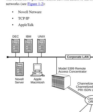
The Model 5399 provides remote network access to the following networks (seeFigure 1-2):
• Novell Netware • TCP/IP
[image:26.612.162.474.121.496.2]• AppleTalk
Figure 1-2. The Model 5399 as a Remote Access Server DEC
Model 5399 Remote Access Concentrator Apple
Macintosh IBM UNIX
Ethernet
Corporate LAN
Novell Server
Central Office Channelized T1, Channelized E1 or
PRI ISDN Lines
The Model 5399 also provides terminal to host connectivity to the following:
• UNIX hosts (using TCP/IP) • VMS hosts (using LAT) • IBM hosts (using TN3270)
Model 5399 Description
The Model 5399 is a Wide Area Network server capable of supporting domestic ISDN, European ISDN, channelized T1, channelized E1, and other channelized protocols. The Model 5399 can house up to 62 modems to provide the flexibility of terminating calls originated by analog modems, terminal adapters, and routers.
The Model 5399 Remote Access Concentrator module occupies one slot in a System 5000 Hub.
The Remote Access Concentrator supports Windows NT® host tools. Remote Annex Server Tools for Windows NT® allows you to boot and configure the Remote Access Concentrator on a Windows NT® network. For more information, refer to the
Module Features
Processors The module utilizes three 80486 DX2 clock-doubled processors, operating at 64 MHz.
WAN Interfaces These interfaces reside on the module and are accessible via an RJ48C connector on the front panel. Each WAN interface is controlled by one of the 80486 DX2 processors, which also controls the internal modems. The WAN interfaces can accept channelized T1, channelized E1, or ISDN PRI lines.
Memory The module has 8 megabytes of main DRAM. An additional 4 megabytes of DRAM is provided for each WAN interface controller.
Flash Memory The module is equipped with 2 megabytes of Flash memory for image storage.
Modems The Model 5399 Remote Access Concentrator Module can be configured with up to 62 internal DSP-based digital modems. The modems are dynamically downloaded with images to configure them to the
System 5000 Common Management Bus
The management section of the backplane is the common management bus (CMB), a high-speed, multimaster, shared-memory communication channel that connects all modules installed in the hub to one another and to the supervisory module. The modules installed in the hub use the CMB to acquire and distribute configuration and status information.
The supervisory module is an intelligent interface between the Model 5000 chassis and user-installed modules. The supervisory module provides the following services to other modules across the CMB:
• Maintains chassis component information and environmental status
• Stores the primary module configurations
• Restores the module configuration after the module power is cycled or the module is reset
System 5000 Backplane Ethernet Segment Banks
The chassis backplane Ethernet bus consists of 12 Ethernet segments, divided into two banks of six segments each: segments 1 through 6 and segments 7 through 12. Each Model 5399 Remote Access Concentrator module installed in the chassis can be configured to access one bank of six segments, either segments 1 through 6 or segments 7 through 12. For more information, see Setting the Backplane Ethernet Segment on page 2-3.
Within a segment bank, the specific segment to which a Model 5399 Remote Access Concentrator module is connected is determined by setting the segment selection DIP switch on the module. For more information, see Setting the Backplane Ethernet Segment on page 2-3.
System 5000 Service Port Management
The service port, located on the front panel of the chassis, provides a switched serial communication link between the service port and any module in the hub, including the supervisory module. By connecting a terminal to this port, you can change the configuration parameter values for the Remote Access Concentrator installed in the hub.
For more information, see Connecting a Service Port Terminal on page 2-14, Remote Access Concentrator Parameters on page 2-18, and
Firmware and Software
Firmware The Model 5399 Remote Access Concentrator’s ROM contains firmware for performing power-up self-tests and loading operational code. A non-volatile EEPROM stores the configuration parameters.
The Remote Access Concentrator can boot from the boot image in its Flash memory or can boot an image received from a boot server on the network.
ROM Monitor The ROM monitor is an interactive command interpreter that is used to define basic configuration parameter values. All of the information that the Model 5399 Remote Access Concentrator needs to boot an
operational image is defined using the ROM monitor and its command set. ROM Monitor commands are issued from a terminal connected to the service port on the hub chassis. When the Remote Access
Concentrator completes its self tests, the service port terminal displays the ROM monitor prompt. Using the ROM Monitor commands (see Chapter 3), you can:
• Modify and display a set of configuration parameters stored in EEPROM.
• Execute interactive diagnostic tests.
• Receive information and statistics for the hardware configuration and the network.
• Boot theRemote Access Concentratormanually.
Supported Configurations
You can self-boot the Model 5399 Remote Access Concentrator from the image contained in its Flash ROM. The Remote Access Concentrator can also obtain full operational code over the network from one of the following devices:
• UNIX host
• Another Model 5399 Remote Access Concentrator configured as a load server
• NT host
Watchdog Timer The Model 5399 Remote Access Concentrator utilizes a watchdog timer that is reset by the software at regular intervals. The watchdog timer reboots the Remote Access Concentrator in the unlikely event of an internal software error. This feature enables the Remote Access Concentrator to run for long periods of time without intervention.
Front Panel
The Model 5399 Remote Access Concentrator’s front panel consists of:
• Annunciator LED
• Segment Connection LEDs • Module Status LEDs
• WAN 1 Network Status, Alarm, and Port Usage LEDs • WAN 2 Network Status, Alarm, and Port Usage LEDs • WAN 1 Port Connector
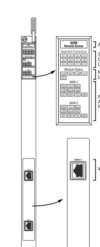
Figure 1-3 illustrates the Model 5399 Remote Access Concentrator’s front panel. The front panel components are described in the following paragraphs.
Figure 1-3. Model 5399 Remote Access Concentrator Front Panel Annunciator
Segment Connection LEDs
WAN 1 Port WAN 2 Port Module Status LEDs
Network Status, Alarm, and Port Usage LEDs
WAN 1 WAN 2
Front Panel Components
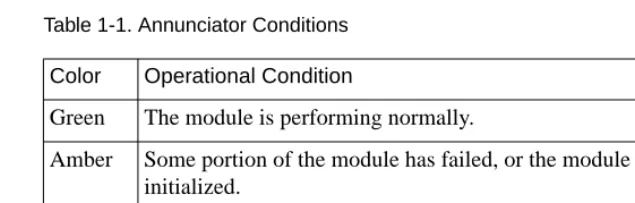
Annunciator The Annunciator backlights the model number of the module and indicates, by its color, the operational condition of the module.Table 1-1
[image:34.612.160.478.196.297.2]describes the Annunciator conditions.
Table 1-1. Annunciator Conditions
Segment
Connection LEDs
The Segment Connection LEDs indicate which backplane Ethernet LAN segments are being used. There are 12 green LEDs, labeled S1 through S12, for the 12 Ethernet segments. When an LED is illuminated, it indicates that the Model 5399 Remote Access Concentrator is connected to the corresponding backplane Ethernet LAN segment; when off it indicates that the corresponding backplane Ethernet LAN segment is not connected.
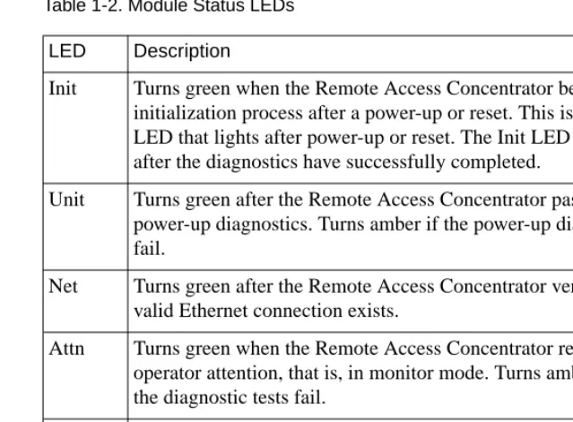
Module Status LEDs The Module Status LEDs are a group of five LEDs that display the status of the activity of the Model 5399 Remote Access Concentrator.Table 1-2
describes the Module Status LEDs.
Color Operational Condition
Green The module is performing normally.
Amber Some portion of the module has failed, or the module is being initialized.
Table 1-2. Module Status LEDs
Network Status and Alarm LEDs
The Network Status and Alarm LEDs display network activity during system operation.Table 1-3 describes the alarms. There are two sets of Network Status and Alarm LEDs, one set for each WAN port.
Technical Support personnel can use this information to diagnose problems.
LED Description
Init Turns green when the Remote Access Concentrator begins the initialization process after a power-up or reset. This is the first LED that lights after power-up or reset. The Init LED turns off after the diagnostics have successfully completed.
Unit Turns green after the Remote Access Concentrator passes the power-up diagnostics. Turns amber if the power-up diagnostics fail.
Net Turns green after the Remote Access Concentrator verifies that a valid Ethernet connection exists.
Attn Turns green when the Remote Access Concentrator requires operator attention, that is, in monitor mode. Turns amber when the diagnostic tests fail.
Table 1-3. Network Status and Alarm LEDs
Port Usage LEDs The Port Usage LEDs, labelled 25%, 50%, 75%, and 100%, indicate the approximate percentage of B channels that are being utilized. There are two sets of Port Usage LEDs, one set for each WAN Port. These LEDs are normally green. If all available B channels are in use, they turn amber until at least one call disconnects.
WAN Interface Ports The two WAN interface ports provide access to Channelized T1, Channelized E1, or ISDN PRI lines. The WAN Interface ports come with 8-pin, RJ48C jacks for attaching the T1, E1 or ISDN cable connectors.
Alarm Description
TEST The network TEST indicator is ON (amber) when the WAN Interface is looped back. Loopback tests are activated either locally by the user or by the telephone company.
SYNC The SYNC indicator is ON (green) when the WAN interface is properly synchronized with the received network signal and is receiving proper framing information.
LOS The LOS indicator is ON (amber) when the WAN interface is detecting invalid synchronization pulses on the network interface receiver. When a LOS condition exists, the Remote Access Concentrator transmits a YELLOW alarm to the remote system.
RED The RED alarm indicator is ON (amber) during a locally detected carrier failure. During the RED alarm condition, a YELLOW alarm is transmitted across the telephone network. YELLOW The YELLOW alarm indicator is ON (amber) when receiving
a YELLOW alarm condition from the telephone network. This indicates a failure detected at the other end of the link (the Central Office).
Physical Characteristics
The Model 5399 Remote Access Concentrator module has the following characteristics:
• Dimensions:
Height: 19 in. (47.5 cm) Width: 1.2 in. (3 cm) Depth: 11 in. (27.5 cm)
• Weight:
10 lbs (4.5 kg).
• Electrical Specifications:
• Power Consumption: 90 W at 48 VDC
• Thermal Rating: 307 BTU/hr maximum
• Environment:
• Operating temperature: 5° to 40°C.
• Non-operating temperature: -25° to 65°C.
• Operating humidity: 85% maximum relative humidity, non-condensing.
• Non-operating humidity: 95% maximum relative humidity, non-condensing.
• Operating shock: 10G peak 1/2 sine wave, 11 ms duration.
• Operating vibration: random vibration 1.2 *10-3 G2/Hz, 12 to 198 Hz.
• Operating altitude: 0 to 4,000 meters.
• Transportation vibration and shock: NSTA project 1A standard in shipping container.
• Approvals:
• Meets safety requirements of Underwriters Laboratories for UL 1950 and CSA C22.2 No. 950.
• Meets EMI requirements of FCC Class A and EN55022 Class A with shielded and unshielded cables.
• Meets US and Canadian Telcom requirements per FCC Part 68 and IC CS-03.
• MTBF:
50,000 hrs. (estimated), calculated @ 25°C (Mil Std 217).
• Front clearance requirement (for connectors and
cables):
Remote Access Concentrator
Module
T
his chapter describes how to install your Model 5399 Remote Access Concentrator Module hardware and software, and connect it to a System 5000 Hub. This chapter provides the following information:• Before You Begin
• Installing the Model 5399
• Testing the Installation
• Connecting a WAN Interface
• Connecting a Service Port Terminal
• Initial Setup and Using the ROM Monitor
• Auto-initializing the ROMs
• Installing the Software and Loading the Operational Image
• Self-booting the Model 5399
• Invoking the Console Monitor
Before you Begin
To successfully install the Model 5399, you need:
• A 3/16-inch flat-tip screwdriver
• An antistatic mat and wrist strap (attached to an antistatic leash)
• An appropriate subnet mask
• A host with Model 5399 software installed (if not booting from FLASH memory)
The Model 5399 can receive its operational image from any one of these sources:
• A UNIX host running erpcd • FLASH memory (self boot)
• Another Model 5399 configured as a boot host • Any host supporting TFTP
[image:40.612.160.477.401.546.2]• A Windows NT host running erpcd
Table 2-1 outlines the different configurations the Model 5399 supports.
Table 2-1. Model 5399 Configuration Options
The Remote Access Concentrator supports Windows NT® host tools. Remote Annex Server Tools for Windows NT® allows you to boot and configure the Remote Access Concentrator on a Windows NT® network. For more information, refer to the
Remote Annex Server Tools for Windows NT® User Guide.
Device on which the Operational Software and Image is installed
Model 5399 Must Be Connected to the Network
Input Device used to Enter Basic
Configuration Parameter Values
UNIX Load Host Yes Service Port Terminal Another Model 5399
configured as a load server
Yes Service Port Terminal
Self-boot (from the image contained in Flash memory)
No Service Port Terminal
Installing the Model 5399 Remote Access Concentrator
This section describes how to install the Model 5399 Remote Access Concentrator Module in a System 5000 Hub. Installing the Model 5399 involves seating the backplane connectors to the Model 5000 Hub backplane and verifying the installation.
Preparing for Hardware Installation
This section explains how to prepare the Model 5399 for installation in the chassis.
Setting the Backplane Ethernet Segment
Table 2-1 shows the locations of the configuration jumper and DIP switch
that you must set to select an Ethernet segment. They are:
• Ethernet segment bank selector (J5)
• Ethernet segment selection DIP switch (S1)
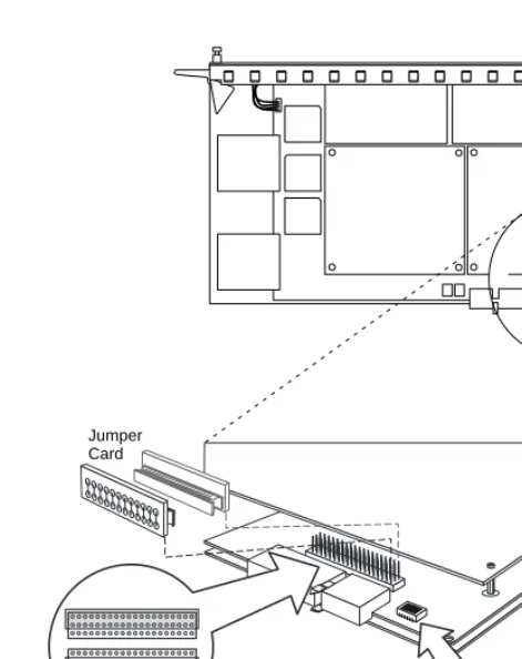
Figure 2-1. Model 5399 Jumper and Connector Locations
Ethernet Segment Bank Selector
The Ethernet segment bank selector (seeFigure 2-1), consisting of three rows of 20 pins (labeled J5, J21 and J22) and a jumper card, determines whether the module connects to Ethernet segments 1 through 6 or segments 7 through 12 at power up. When the jumper card is installed on the two rows of pins nearest the front of the module (using J21), the module has access to segments 1 through 6 (the factory default setting); when the jumper card is installed on the two rows of pins nearest the back of the module (using J22), the module has access to segments 7 through 12.
1
DIP Switch S1 Jumper
Card
ON
The specific segment connection for the module is determined by the segment selection DIP switch (described in the next section).
Segment Selection DIP Switch
DIP switch S1 on the module (seeFigure 2-1) is used to set the default segment selections. Segment selection DIP switch settings are listed in
Table 2-2. Turning a DIP switch number ON selects a particular segment
within the Ethernet segment bank. For example, turning on DIP switch number 1 selects either segment 1 or 7, depending on the position of the Ethernet segment bank selector jumper card.
When the jumper card is installed between J5 and J21, the printed circuit card handle is nearest the front of the module. To install the jumper card between J5 and J22, remove the jumper card, rotate it 180 degrees (so that the printed circuit card handle is nearest the back of the module) and push it onto the pins (see
Figure 2-1).
Network management software cannot override the bank selector setting. The setting (segments 1–6 or 7–12) can only be set while the module is outside the chassis.
Table 2-2. Segment Selection DIP Switch Settings
Installing the Module into the Hub
To install and secure the module into the System 5000 Hub, follow these steps:
1. Remove the blank filler panel from the chassis slot where
you intend to install the module.
2. Verify that the module jumpers are set correctly (seeSetting
the Backplane Ethernet Segment on page 2-3).
3. Extend the inserter/extractor levers to their fully extended
positions (seeFigure 2-2).
DIP Switch S1 Switch Number
Jumper Card Connects J5, J21 (Segment Bank 1-6)
Jumper Card Connects J5, J22 (Segment Bank 7-12)
1 (default) Segment 1 Segment 7
2 Segment 2 Segment 8
3 Segment 3 Segment 9
4 Segment 4 Segment 10
5 Segment 5 Segment 11
6 Segment 6 Segment 12
Figure 2-2. Inserter/Extractor Lever
4. Align the top and bottom edges of the module in the card
guides of the target slot, and push the module into the chassis until the inserter/extractor levers just engage the
Figure 2-3. Inserting the Module
5. Seat the module backplane connectors by simultaneously
pushing the inserter/extractor levers toward the center of
the module front panel (seeFigure 2-4).
Figure 2-4. Seating Module Connectors
6. Tighten the captive retaining screws at both ends of the
Testing the Installation
[image:48.612.244.391.210.570.2]After installing and connecting the Remote Access Concentrator, verify that you have performed the installation correctly by observing the LED indicators and system operation displays on the front panel of the Remote Access Concentrator (seeFigure 2-5).
Figure 2-5. Module LED Display
Annunciator Segment Connection LEDs
WAN 1 Port WAN 2 Port Module Status LEDs
Network Status, Alarm, and Port Usage LEDs
WAN 1 WAN 2
LED Indicators
When the Remote Access Concentrator is operating correctly, the front-panel LEDs (seeFigure 2-5) should appear as follows:
• Annunciator: The annunciator should be green. If the annunciator remains amber after completing the self-tests, refer toChapter 4.
• Segment Connection LEDs: A steady green indicates which Ethernet LAN segment the module is using.
• Module Status LEDs:
• Init: Turns green when the module begins the
initialization process after a power-up or reset. Typically, this is the first LED that lights after power-up. The Init LED turns off after the initial diagnostics have
successfully completed.
• Unit: Turns green after the module passes the power-up
diagnostics. If the Unit LED turns amber, refer to Chapter 4.
• Net: Turns green after the module verifies that a valid
Ethernet connection exists.
The Model Remote Access Concentrator performs a series of self-test diagnostics each time it is reset or powered up. These tests take about a minute to complete and cannot be deactivated. While these tests are running, the annunciator remains amber. The annunciator changes to green upon successful test
• Attn: The Attn LED should be off. The Attn LED turns
green if the Remote Access Concentrator is in Monitor Mode. If the Attn LED is amber or flashing, one of the following failures has occurred:
• Hardware failure. Contact technical support.
• Network or network interface failure. Error message displays on the terminal. If a network or network interface failure occurs, typingq accesses the ROM Monitor prompt. Check the network connection and then see net on page 3-19.
• Load: Turns green when the Remote Access
Concentrator is loading the operational image or dumping a RAM image if there is a failure.
• Verify that the hub front-panel LEDs are properly illuminated.
If the LEDs do not light in the proper manner, or if the system operation displays indicate problems, see Chapter 4 for more details.
Connecting a WAN Interface
Be sure to properly configure the interface before connecting the cable. Some switch types will disable lines connected to an improperly configured device. See the Model 5399 Remote
Access Concentrator Module Network Administrator’s Guide
for details.
A WAN Interface is used to connect the Remote Access Concentrator to channelized T1, channelized E1, or ISDN PRI lines. Follow the
instructions in this section to connect the line to the WAN Interface port.
1. Plug the cable into the WAN Interface port located on the
front panel of the Remote Access Concentrator (Figure 2-6).
[image:51.612.222.446.238.533.2]When the connector clicks into place, the connection is secure. Appendix A describes the WAN Interface port’s signal/pin allocation.
Figure 2-6. Connecting a WAN Interface
Connecting a Service Port Terminal
If your network does not include a BOOTP or RARP server, you must connect a terminal to the service port on the System 5000 chassis front panel and manually configure the Remote Access Concentrator before booting.
To configure the Remote Access Concentrator through the chassis service port, you need:
• An ascii terminal or a portable computer with a serial port and the ability to emulate an ascii terminal. The terminal should be set up for:
– 9600 bps (default) – 8 data bits
– No parity – 1 stop bit – No flow control – ASCII
Table 2-3. Service Port Pin Assignments
RS-232 signals on other pins, such as DTR, CTS, and CD, are ignored.
Connecting the Terminal
To connect the terminal to the service port, follow these steps:
1. Connect the terminal (or a computer in terminal emulation
mode) to the chassis service port with the RS-232 cable.
2. Press to display the Slot Selection menu.
The Slot Selection menu (Figure 2-7) shows the system date and time, lists the modules installed in the chassis by slot number, and lists the available commands.
Terminal
DB-9 DB-25
Function To Service Port DB-9 Pins
Function
2 3 Receive data 2 Transmit data 3 2 Transmit data 3 Receive data 5 7 Signal ground 5 Signal ground
Figure 2-7. Slot Selection Menu
Use this menu to reset the Remote Access Concentrator. For more information, seeAuto-initializing the IP Address
Parameters on page 2-23.
Model 5399 Slot Selection Menu 01/15/97, 10:19:32 AM
Slot 1 Status: Module Description:
1 On-line 5310 Ethernet NMM
2 Configuring 5308 Ethernet Host
3 Other 5308 Ethernet Host
4 (removed) 5308 Ethernet Host
5 Off-line 5308 Ethernet Host
6 Booting 5308 Ethernet Host
7 On-line 5308 Ethernet Host
8
9 Off-line 5399 Remote Access Concentrator
10 11 12 13 14
c - Connect to slot (Press CTRL-T to break connection) s - Select Supervisory Module Main Menu r - Reset module
Initial Setup and Using the ROM Monitor
After installing the Remote Access Concentrator software on the file server host, collect the following information, which is required to determine the unit’s boot parameters:
• The location (directory path) of the download files on the host (tftp only).
• Whether the Remote Access Concentrator and host are on the same subnet or separated by one or more routers. • Whether the host going to use tftp or erpcd (requires a
UNIX or Windows NT®host) to serve the Remote Access Concentrator download code.
The Remote Access Concentrator needs these parameters to perform an initial boot when loading the software. Enter these parameters into the EEPROM using the ROM monitor commands, which are accessed through a service port terminal. See Chapter 3 for more information about these commands.
The Remote Access Concentrator supports the Bootstrap Protocol (BOOTP) and the Reverse Address Resolution Protocol (RARP) which can be used to obtain some of the information listed. If you have a host running BOOTP or RARP to serve the Remote Access Concentrator the information, the server will boot without user intervention. For more information about using these protocols, seeAuto-initializing the IP
Address Parameters on page 2-23.
The Remote Access Concentrator supports Windows NT® host tools. Remote Annex Server Tools for Windows NT® allows you to boot and configure the Remote Access Concentrator on a Windows NT® network. For more information, see the Remote
Remote Access Concentrator Parameters
[image:56.612.159.480.238.570.2]The Remote Access Concentrator requires that you set certain parameters from the ROM monitor before booting the unit from a host. Once the Remote Access Concentrator is booted, you can change these parameters using the na utility. Any changes to these parameters will require the unit to be rebooted to take effect.Table 2-4 provides a brief description of these parameters.
Table 2-4. Server Parameters
Parameter Description
Internet address A unique 32-bit universal identifier that is specified in dotted-decimal notation.
Subnet mask Defines which portion of the Internet address is the network (all ones), the subnet (all ones), and the host (all zeros) address.
Preferred load host address The Internet address of the host from which you want to boot.
Load/dump gateway Internet addres
The Internet address of the router, for which you will be prompted, if the preferred load host is on a different network.
Broadcast address An Internet address with a host id of all ones (or all zeros for support of older 4.2 BSD systems) to which all hosts on a particular subnet will respond.
Type of IP encapsulation Specifies the method for accessing the physical and network layer of the transmission media. The default is: ethernet (for DIX Ethernet-II). This parameter can also be set to ieee802 (also referred to as LLC/SNAP). Broadcast flag Determines whether the Remote Access
Initializing the Remote Access Concentrator
This section describes how to set up the Remote Access Concentrator, make the connection to the System 5000 Hub for the first time, and enter Monitor Mode to configure the module.
To initialize the Remote Access Concentrator and enter Monitor Mode:
1. Use a terminal connected to the chassis service port to verify
that the Remote Access Concentrator is operating properly.
The Slot Selection menu is displayed. The Remote Access Concentrator should be listed next to the slot number in which it is installed.
2. Reset the Remote Access Concentrator by typing r and then
entering the slot number of the chassis that contains the server.
The following prompt is displayed:
Are you sure you want to RESET this module? (Y/N):
3. Answer the question by entering y.
4. Within 10 seconds, connect to the Remote Access
Concentrator by typing c and then entering the slot number of the chassis that contains the server.
5. Wait for the following prompt:
To enter “Monitor Mode” please depress the SPACE key within 10 seconds.
6. Press the space bar within 10 seconds.
After a few seconds, the following message is displayed:
Monitor Mode selected, please wait for Confidence tests to complete.
After about a minute, the following message is displayed, followed by the monitor prompt:
System Reset - Entering Monitor Mode
monitor::
7. If you want to clear out the stored parameters from a
previously used slot (reset the hub slot), continue on with Step 8. If you do not want to reset the hub slot (if, for example, you are performing a hot swap), skip to Step 16.
8. On the service port terminal, press then -T to
display the Slot Selection menu.
9. Press s.
The Supervisory Module Main Menu is displayed.
10. Press m to select the Module Information menu.
The following prompt is displayed:
Enter slot # (1-14):
11. Enter the slot number of the module you want to boot.
The module information and status are displayed and you are prompted to reset the module, set the module configuration to default, or return to the previous menu.
12. Press d to select the module configuration default.
The following message is displayed:
Are you sure you want to set module DEFAULT configuration? (Y/N):
13. Press y.
The Module Information menu is displayed.
14. Press twice.
The Slot Selection menu is displayed.
15. Press c and the slot number.
16. Verify the Remote Access Concentrator hardware
configuration by typing config and pressing at the
monitor prompt.
The screen display looks similar to this:
Escape
Return
REVISION/CONFIGURATION INFORMATION
ROM Software Rev: 1110
Board ID: 64 Board Type: 5399
CPU Type: 486DX2 Ethernet Address: 00-80-2d-xx-xx-xx Memory size: 8 Meg EEPROM size: 65504
Flash size: 2 Meg Flash ID:0089
WAN 1: PRI E1 ETSI Revision: VERSION A MGR=1.159 WAN 2: PRI E1 ETSI Revision: VERSION A MGR=1.159
SLC 1
SLC SRAM Size: 128 K Modem Count: 31 Modem Rev: 0
SLC 2
SLC SRAM Size: 128 K Modem Count: 31 Modem Rev: 0
Hub Slot Hub CMB HW Rev Hub EE Rev Hub EE Seg Sel Hub Jmpr Seg Sel
17. To verify and record the unit’s Ethernet address, type addr
-d an-d press at the monitor prompt:
The screen display looks similar to this:
18. Verify that the Remote Access Concentrator is on-line by entering the net command. The following prompt appears:
Enter Segment to be used [1]:
A “pass” or “fail” message is displayed. If fail is displayed, try verifying the network from another device.
Once the Remote Access Concentrator is on-line, you can download the image software to the server (seeInstalling the Operational Software and
Loading the Image on page 2-32).
Return
monitor:: addr -d
Ethernet address (hex): 00-80-2d-XX-XX-XX Internet address: <uninitialized>
Subnet mask: 255.255.0.0 Broadcast address: 0.0.0.0
Preferred Load Host address: <any host> Preferred Dump Host address: 0.0.0.0
Load/Dump Gateway address: 0.0.0.0
Booting the Remote Access Concentrator
You can boot the operational software by downloading the image from a host system or another Model 5399 Remote Access Concentrator, or by using the image contained in Flash memory (self-boot). However, before actually booting the unit, you must first initialize the IP address
parameters either manually or by using the auto-initialize feature. The following sections describes the two methods of initializing the IP address parameters, and the various boot methods.
Auto-initializing the IP Address Parameters
The Remote Access Concentrator is distributed without an IP address or preferred load host defined in ROM. When the device is booted, the Remote Access Concentrator attempts to auto-initialize itself using BOOTP (bootstrap protocol) and RARP (Reverse Address Resolution Protocol).
This method of initializing the IP address parameters is generally done when booting from a host system (not when self-booting).
The Remote Access Concentrator supports the BOOTP and RARP protocols. Use these protocols to obtain boot information from a UNIX host without requiring any manual set-up on the Remote Access Concentrator.
• BOOTP allows a diskless client to determine its IP address, the IP address of the server, and the name of the file to be loaded into memory.
• RARP maps a hardware address into an IP address.
If all requests fail, the Remote Access Concentrator will return to the ROM monitor (if in Test mode) or continue the auto-initializing procedure indefinitely (if in normal mode).
BOOTP
For a successful BOOTP retrieval, a bootpd must be running on a host on the same subnet as the Remote Access Concentrator (or have a correctly-configured router on the same subnet that supports BOOTP forwarding) and must have the appropriate information in the bootptab file. The Remote Access Concentrator’s BOOTP implementation adheres to rfc951, rfc1048, and rfc1084. A sample bootptab file entry used to initialize the Remote Access Concentrator named terminator looks like this:
In the previous example:
• sm isthe subnet mask.
• gwis the load/dump gateway address. • vm is the Vendor Magic Cookie. • htis host type (1=Ethernet).
• hais theRemote Access Concentrator’s hardware address (Ethernet Address).
• ip is theRemote Access Concentrator’s Internet Address.
remoteannexdefault:\
:sm=255.255.255.0:gw=132.245.22.66:\ :hn:vm=auto:to=-18000:
terminator:\
When the Remote Access Concentrator receives aBOOTP response with the sm, gw, and ip set, it sets the respective parameters: subnet_mask,
load_dump_gateway, and inet_addr. The Vendor Magic Cookie must
be set to auto. This indicates that bootpd should respond to the client (Model 5399 Remote Access Concentrator in this case) with whatever format the client requests; the Model 5399 Remote Access Concentrator (client) always makes requests with the Vendor Magic Cookie set to 99.130.83.99.
The bootpd adds the address of the host on which it is running as the
Server Address in the bootp response message. The ROMs use the Server Address as the preferred load host and store it in the pref_load_addr
parameter.
The host running bootpd (the preferred load host) must also be running erpcd or tftpd.
RARP
If the Remote Access Concentrator does not receive a successful BOOTP response, it uses RARP to get the boot information. For a successful RARP retrieval, TCP/IP must be running on a host that is on the same subnet as the Remote Access Concentrator, and the host’s ARP table must be initialized with the Remote Access Concentrator’s Internet and Ethernet addresses (see the arp man page for arp –s).
The only boot information that RARP provides is the Remote Access Concentrator’s Internet address. The ROMs save this information in the
inet_addr parameter. The ROMs use default information for the subnet
The host serving the Remote Access Concentrator its boot information must be running on the same subnet as the Remote Access Concentrator because the Remote Access Concentrator broadcasts BOOTP and RARP queries using the “this network” IP address, 255.255.255.255.
If BOOTP and RARP fail, the Remote Access Concentrator transmits an IPX Advertisement Request for Service.
If all requests fail, the Remote Access Concentrator returns to the ROM monitor (if in Test Mode) or continues the auto-initializing procedure indefinitely (if in Normal Mode).
Manually Initializing the IP Address Parameters
To configure the Remote Access Concentrator for your specific needs, the IP address parameters can be manually initialized by performing the following steps:
1. Enter the addr command at the monitor prompt.
The following prompt is displayed:
Enter Internet address::
2. Enter the IP address for the Remote Access Concentrator.
You are prompted to enter the server subnet mask, preferred load host, preferred dump host, IP packet encapsulation, and load broadcast flag. The defaults are listed after each prompt.
3. Modify the parameter next to each prompt, or press to
retain the current setting.
Booting Using BFS
Perform the following steps to boot the Remote Access Concentrator using BFS:
1. Initialize the IP address parameters using either the
auto-initialize or manual auto-initialize method.
The auto-initialization method is described inAuto-initializing
the IP Address Parameters on page 2-23. The manual
initialization method is described inManually Initializing the
IP Address Parameters on page 2-26.
2. Enter the boot command.
If you do not enter a file name with the command, you are prompted for one (the default file name is displayed at the prompt: oper.64.enet). Press to boot using the default file name.
The following example shows a typical screen display for a BFS boot using erpcd on UNIX or Windows NT:
Enter boot file name[oper.64.enet]::
Waiting for CMB Config Block Info...
Requesting boot file ”oper.64.enet”.
Unanswered requests shown as ’?’,transmission errors as ’*’.
Requesting boot from 192.9.200.88 via Ethernet... Booting BFS file using open delay of 8
Booting BFS file from 192.9.200.88
Header received OK. Received data blocks shown as ’.’. . . . . . . .. . . . . . . .. . . ? . . . . . . . . . . * . . . . . . . . * . . . . . . . . . . ? . . . . . . . EOF
The download takes between 30 and 60 seconds for a Model 5399 Remote Access Concentrator booting over the local network. After the download is complete, the Power, Unit, and Net LEDs remain on. If these LEDs do not remain on (indicating a problem), see Chapter 4.
Once the Remote Access Concentrator is booted, Monitor Mode is no longer operational. The Remote Access Concentrator is up and running, and the following message is displayed:
Booting Using TFTP
The procedures detailed in this section assume that your TFTP daemon (tftpd) is started in/etc/inetd.conf (or other appropriate directory on
your system) with a configuration line similar to this:
tftp dgram udp wait root /usr/etc/in.tftpd in.tftpd -s/tftpboot
If you leave off the-s /tftpboot, a chroot will not be done,
and your system will be insecure.
To set up directories and files, and use TFTP to boot the Remote Access Concentrator, follow these steps:
1. Initialize the IP address parameters using either the
auto-initialize or manual auto-initialize method.
The auto-initialization method is described inAuto-initializing
the IP Address Parameters on page 2-23. The manual
initialization method is described inManually Initializing the
IP Address Parameters on page 2-26.
2. Enter the image command at the monitor prompt.
As prompted, enter the following information: • Appropriate boot image name
• Boot directory
• Dump filename
The default image file name is:oper.64.enet
The following example shows how the image command is used to set up a Remote Access Concentrator boot from the /tftpboot/
annex/ directory. When you enter the load directory name, make
Image name: <invalid or uninitialized> Default: “oper.64.enet”
Enter Image name::oper.64.enet Image name: “oper.64.enet” TFTP load directory:
Enter TFTP load directory::/annex
TFTP Dump path/filename: <uninitialized> Default : “dump.134.117.6.34”
Enter TFTP Dump path/filename::/annex/mydumpfile Using current TFTP Dump path/filename.
monitor::
3. Issue the following commands to prepare the tftp dump file.
touch /tftpboot/annex/mydumpfile
chmod 622 /tftpboot/annex/mydumpfile
4. Enter the boot command.
The boot command display looks similar to this:
Enter boot file name[oper.64.enet]::
Waiting for Config Block Info...
Requesting boot file ”oper.64.enet”.
Unanswered requests shown as ’?’,transmission errors as ’*’.
Requesting boot from 192.9.200.88 via Ethernet... Booting BFS file using open delay of 8?
Booting TFTP file using open delay of 8 Booting TFTP file from 192.9.200.88
Header received OK. Received data blocks shown as ’.’. . . . . . . . . . . . . . . . . . . . . . . . . . . . . . . . . . . . EOF
Once the Remote Access Concentrator is booted, Monitor Mode is no longer operational. The Remote Access Concentrator is up and running, and the following message is displayed:
Self-booting the Remote Access Concentrator
The Remote Access Concentrator comes equipped with Flash memory that contains an operational image you can use to self-boot the module. To self-boot your Remote Access Concentrator, perform the following steps:
1. Initialize the IP address parameters using the manual
initialize method.
The manual initialization method is described inManually
Initializing the IP Address Parameters on page 2-26.
2. Enter the sequence command at the monitor prompt.
The following prompt is displayed:
Enter interface sequence [net]::
3. Enter self, net as the sequence.
The monitor prompt is displayed.
4. Enter the boot command at the monitor prompt.
The display looks similar to this:
monitor:: boot
Waiting for CMB Config Block Info...
Requesting default boot file “OPER_64_ENET.SYS” for MOP/VMS\ loads and “oper.64.enet” for all other protocols. Unanswered requests shown as ‘?’, transmission errors as ‘*’.
Booting file: “OPER_64_ENET.SYS” from SELF
Loading image from SELF ...
... Load Completed
Booting from a Windows NT
®Host
To boot the Remote Access Concentrator from a Windows NT® host, you must have Remote Annex Server Tools for Windows NT® installed. Remote Annex Server Tools for Windows NT® uses the expedited remote procedure call daemon (erpcd) running on a Windows NT® server. Erpcd responds to all Remote Access Concentrator boot and dump requests. Refer to the Remote Annex Server Tools for Windows NT® User Guide
for additional information.
Booting from Another Model 5399 Remote Access
Concentrator
You can boot from another Model 5399 Remote Access Concentrator, if the Model 5399 Remote Access Concentrator you are trying to boot from is configured as a boot server. You can do this by using na or admin to set the annex server_capability to image. See the Remote Annex
Administrator’s Guide for Unix for additional information.
Installing the Operational Software and Loading the Image
Use this section if you have successfully connected the Remote Access Concentrator to your LAN.
This section describes:
• How to install the Remote Access Concentrator module’s operational software and image on a device that resides on a network accessible to the module.
Installing to and Loading from a UNIX Host
This section contains a description of what you need to do to install the Remote Access Concentrator module’s operational software and image to a UNIX host. See the Remote Annex Administrator’s Guide for UNIX for more details.
1. Install the image on a UNIX host. The software installation
notes describe how to do this.
2. Execute the ROM Monitor addr command:
• Enter the module’s Internet address.
• Modify any other parameters that the Remote Access Concentrator may require for the initial boot, i.e., the preferred load host’s Internet address and the subnet mask (see addr on page 3-4).
3. Execute the boot command.
After successful execution of the boot command, the module is up and running (see boot on page 3-8).
Invoking the Console Monitor
After the image boots, you can invoke the Console Monitor by pressing on the service port terminal. The following prompt appears:
Console monitor:
At the Console Monitor prompt, entering help or ? displays the available options:
• afd (displays the status of the Automatic Firmware
Download process - used only for the WAN interfaces).
• cli (starts the Command Line Interpreter on the current port)
• dump (from the Remote Access Concentrator to the host
and reboots).
• help or ? (displays the available options).
• info (displays configuration information for the Annex).
• leds (displays the current front panel LED status).
• quit (quits and returns to quiet console)
• reboot filename (reboots the Annex).
• rom (returns the Remote Access Concentrator to the ROM
Monitor).
• syslog (displays syslog messages).
T
his chapter describes the ROM Monitor commands that are available in Monitor Mode. Access these commands through a terminal connected to the service port (located on the front of the hub chassis).The ROM Monitor commands allow you to set a subset of the
configuration (EEPROM) parameters. Some of these parameters, like the unit’s IP address, are required for booting the Model 5399 Remote Access Concentrator; some parameters, like the broadcast address, are required if the network configuration differs from the supplied defaults.Table 3-1
lists the ROM Monitor commands.
Other parameters, although not required, are recommended for the Remote Access Concentrator’s initial boot. Setting these parameters, rather than using the assigned defaults, minimizes errors during the initial boot. For example, setting the parameter that defines the preferred load host enables the Remote Access Concentrator to load by requesting assistance from a specific host, rather than by broadcasting that request to all hosts on the subnet.
After the Remote Access Concentrator has booted, you can define the same parameters you defined using the ROM Monitor, by using the host-based na utility, the local CLI admin command, or SNMP. The Remote
Annex Administrator’s Guide for UNIX describes the na utility in detail.
See Chapter 4 for information on power-up and boot procedures.
Default or current values for parameters are displayed in brackets. For example:
Enter broadcast address [132.245.6.255]:
At the prompt, enter a different value, or press to leave the displayed value unchanged.
You can use unique abbreviations for all ROM Monitor commands except
erase. For example, enter boot as bo, and enter net as n. If you enter an
abbreviation that is not unique, an error message describing the command as ambiguous is displayed on the service port terminal.
Command Descriptions
Table 3-1 lists the ROM Monitor commands; the following subsections
describe them.
Table 3-1. ROM Monitor Commands
(continued on next page)
Return
Command Description Use
addr [-d] Displays and sets EEPROM values relevant to IP network addressing, including the unit’s IP address.
Changing IP configuration parameters.
boot [-v] [<file>] Manually boots and loads the unit’s operating code.
Changing the address o