.-.-....
-.
.
-
AT&T
999-300-193IS:::::
~:::::::::::.::::::::
::::::
:::::::::::::::::::::::::::
:::::.
,
...
:.
• • • • • • • • II • • • • • • • • •
:.:.:.:.:.:.:.:.:.:.:.:.:
..
. . .
.
. . .
.:.:.:.:.:
. . . .
.
:.:.:.:.:.:.:.:.:.:
.:.:.
:.:.:.:.:.:.-,·
... .
... .
:.:.:.:.:.:.:.:.:.:.:.:.:.
·
... .
:.:.:~:.~.:-:.:.:.:.:.:.:.:.:.:.:.
·
... .
:.:.:.:.
'... .
:.:.:.:.:.:.:.:.:.:.:.:.
·
...
:.:.:.:.~.~..
~'. ,... .
I:.:.:.:.:.:.:.:.:.:.:.: .:.:.:.:.:.;a.
' • • • • • • • • • • • • • • • • • • • • • • • • • • • • • • • • • • - 1
-'
... .
' ... I·
t·
• • • • • • • • • • • • • • • •... .
_a_...
~.:·
...
__.
·
...
-
.
...
·
... .
:.:.
...•...
:.:.:.:.:.:.:.:.:.:.:
.:. :.:.:.:.:.:
.
...•...•...
·
... .
·
... .
••. :.:.:.:.:.:.:.:.:.:. :.: .:.:.: .:.:.·1
...
~..
:.
.
'.
,.
ATs.T UNIX™ PC
EIA/RAM Combo Board
Installation Guide
©1985 AT&T
All Rights Reserved Printed in USA
NOTICE
The information in this document is subject to change without notice. , AT&T assumes no responsibility for any errors that may appear in
this document.
Certified to comply with Class B limits, Part 15 of FCC
Rules. See instructions i f interference to radio operation
Contents
Installation of EIA/RAM Combo
Expansion Boards 1
Pinouts for RS-232 Ports J1 and
J2 Combo Cards 1
Required Tools 2
Expansion Memory Installation 2
Installing an Expansion Board 6
The Expansion Slots 6
Installing Expansion Software 10
Removing a Board 12
Installation of EIA/RAM Combo Expansion Boards
This AT&T UNIX PC Installation Guide tells you how to install any of the following expansion options:
o O.5MB RAM Expansion Board (no EIA ports) o 2.0MB Expansion Board (no EIA ports)
o O.5MB EIA/RAM Combo Board *0 1.0MB EIA/RAM Combo Board *0 1.5MB EIA/RAM Combo Board
o O.5MB RAM chip set o Two O.5MB RAM chip sets
o Dual EIA Port Board (no RAM)
*Before installing these boards in your system, you must insert the ICs included in the RAM chip sets in their proper locations on the boards according to the
following procedures. If you are installing any of the other boards, which do not require insertion of
additional ICs, follow the instructions in the installation section in this manual.
Once you have installed the EIA/RAM Combo Board turn to "Setting Up Expansion Ports" in the Owner's Manual.
Pinouts for RS-232 Ports Jl
and
J2on
Combo CardsJ & J2
Pin Signal
2---TX 3---RX 4---RTS 5---CTS 6---7---GND 8---CD 20---DTR 24---CLK OUT 15- - - - -.-TXCK 17---RXCK
Insta11ation of EIA/RAM Combo Expansion Boards
Required Too1s
o Small Phillips-head screwdriver (3/16") for removal and replacement of expansion slot covers (Xcelite model X-101 or Xst-101 or equivalent) .
o Chip insertion/removal tool. This is
required for relocation and installation of RAM chips on the 1.0 and 1.5 EIA/RAM Combo board.
o Pliers (for RAM only boards) .
Expansion Memory Insta1lation
The IC insertion/removal tool is required to install the expansion memory chip set.
For the 1MB Combo board, you will have to first
relocate memory ICs installed at the factory. See Table 1 for jumper and memory population.
Table 1. Jumper and IC Locations
RAM WI W2 W3 Rows PopuJated with rcs
0.0 OFF OFF OFF NONE
0.5 OFF ON ON 5 & 6
1.0 ON OFF ON 7 through 10
1.5 ON ON OFF 5 through 10
The additional memory rcs must be instal1ed in
specified sections of the memory expansion board. To install the memory rcs, carefully follow the guidelines in the remainder of this document:
Installation of EIA/RAM Combo Expansion Boards
Caution
Before handling the expansion board or the memory chip set, ground yourself by touching an electrically grounded metal surface. A static charge could damage the memory. Always avoid touching the printed side of the board. Keep one hand on a metal surface (for example,
the base of the UNIX PC) while installing the memory IC set.
The memory ICs must be properly oriented when they are installed. The notch in the IC must point towards the flat connector located on the edge of the expansion board. Do not assume that the printing on the top of the module will orient i t correctly. See Figures 1 and 2 for proper orientation of the memory ICs.
When installing the additional memory ICs, work on a clean, flat surface that will support the expansion board while you are pressing the ICs into place.
One MB Combo
1 To install the memory chip set for 1.0MB first determine the locations where the jumper(s) and the ICs must be placed (see Table 1 and Figure 1) .
Caution
Jumper locations and pins on the rcs must not be bent. Jumpers and ICs must be positioned carfully and then pressed
firmly into place.
,2 Carefully remove the jumper at W2 and place i t in jumper position WI.
Insta11ation of EIAjRAM Combo Expansion Boards
4
36 IC's Installed (18 from locations 5A (Jumper Location) through 5K and 6A through 6K
W1 Installed plus 18 new IC's from chip set)
- - - \ -.. - .. - - - - 5 - 6 7 8
4--10---
11=:::..•
Edge Connector
A:::::::: ::::::::
~ L=:J c=:J c=:J:::::::: :::::::: c=J L=:J c=J c=J :::::::: :::::::: c=J c=J c=J c=J :::::::: :::::::: c=J c=J c=:::J c=:::J
:::::::: :::::::: c=J c=J c=:::J c=J
:::::::: :::::::: c=:::J c=J c=:::J c=:::J
:::::::: :::::::: c:=:::J c=J c=J c=J :::::::: :::::::: c=J c=J c=J c=J
K :::::::: :::::::: c=J c=J c=:::J c=:::J
1
18 IC's removed and reinstalled in locations
7 A through 7K and 8A through 8K
* Notch must be pointing toward edge connector on expansion board
Figure 1 One MB Expansion Ie Insta11ation Location
3 With the Ie removal tool, remove the memory Ie's located at SA through SK and 6A through 6K on the expansion board.
4 Reinstall these Ies in locations 7A through 7K and 8A through 8K respectively.
5 Remove 18 additional Ies from their
[image:11.402.18.352.91.514.2]Installation of EIA/RAM Combo Expansion Boards
Note
There are 20 Ies in the chip set. Store
the two extra Ies in a safe place for use as spares.
6 Install these 18 Ies in locations 9A through
9K and lOA through 10K.
7 Install the expansion board as described in
the installation section of this manual.
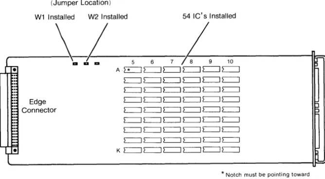
One and one hal f MB Combo
1 To install the memory chip set for 1.5MB
first determine the locations where the jumper(s) and the Ies must be placed (see
Table 1 and Figure 2) .
2 Leave the jumper at W2 and move the jumper
from W3 to W1.
3 Remove the 36 additional Ies from their
packaging. Inspect the Ies and ensure that
their pins are straight.
Note
There are 20 Ies in each chip set.
Store the four extra Ies in a safe place for use as spares.
4 Install these Ies in locations 7A through 7K,
8A through 8K, 9A through 9K and lOA through
10K.
5 Install the expansion board as described in
the installation section of this manual.
Installation of EIA/RAM Combo Expansion Boards
(Jumper Location)
W1 Installed W2 Installed 54 IC's Installed
---~-a
1-
5 6,1--9
10-i~r-rre
A.~~~~~~,Ii:-:':
Edge Connector
c:=J c:=J c:=J c:=J c:=J c:=J c=J c=J c=J c=J c=J c=J c:=J c:=J c:=J c=J c:=J c:=J c:=J c:=J c:=J c:=J c:=J c:=J c:=J c=J c:=J c=J c=J c:=J c=J c:=J c=J c=J c:=J c=J c=J c=J c=:J c=:J c=:J c=:J
. , ~ K c=J c=J c=J c=J c=J c=J
L~
* Notch must be pointing toward edge connector on expansion board
Figure 2 One and One Half MB Expansion Ie Location
Installing
an
Expansion BoardThe location information given in Appendix A must be followed carefully when installing expansion boards into the UNIX PC. Select the expansion slots you are going to use before continuing with this procedure.
Also, i f there are expansion boards already installed on your UNIX PC, you may have to relocate them
according to Appendix A. For expansion board removal follow the expansion board removal procedures in this manual.
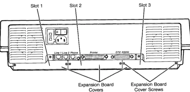
The Expansion Slots
The UNIX PC has three expansion slots in the back of the system. Each slot is covered by a metal plate located on the rear of the unit (see Figure 3). They are numbered as 1, 2, and 3 from left to right as viewed from the rear of the machine.
[image:13.401.15.349.100.284.2]Installation of EIA/RAM Combo Expansion Boards
Slot 1 Slot 2 Slot 3
Figure 3 Rear View of UNIX PC
The only tool needed to install an expansion board is a small Phillips-head screwdriver with a blade diameter of about 3/16" (Xcelite model X-lOl or XST-lOl are examples) .
1 Before you begin the installation procedure, close all open windows except the Office. Select \ Shutdown \ from the Office command menu, press <Enter>, wait for Ready to turn
power Off, press return to reboot message and then turn the UNIX PC off.
Since RAM boards are static sensitive, i t is a good idea to leave the PC plugged in so the equipment is continually grounded.
2 Remove the two screws from the cover(s) of the expansion slot(s) you have selected. (Be carefu1 not to strip the screws.) The covers come off easily. Retain the covers and
screws; you will use the screws to hold the Combo boards in place. For other boards, covers and screws will be replaced at the end of installation.
[image:14.399.47.372.92.250.2]Installation of EIA/RAM Combo Expansion Boards
8
Caution
Before handling an expansion board, ground yourself by touching an
electrically grounded metal surface. A static charge could damage the memory, so always avoid touching the printed side of the board. If possible, keep one hand on a metal surface (for
example, the base of the UNIX PC) while installing the board.
3 Grasp the board from the component side, allowing your fingers to rest on the edges only.
4 With the edge connector entering the slot first, component side up, fit the board edges into the grooves in the side tracks of the expansion slot, and slide the board in (see Figure 4) .
It should slide in easily. If i t binds, there may be a defect in the board or slot, or you may have inserted the board
incorrectly.
5 Using your thumbs, put slight pressure on the back edge of the board until the board snaps into place.
Installation of EIA/RAM Combo Expansion Boards
1011111111111 Imlllllliol
Board Cover Plate
RS-232 Ports
Figure 4 Inserting an Expansion Board
6 For Combo boards, replace the cover screws (being careful not to strip the screws) to hold the expansion board in place. Retain expansion board cover for future use. For
RAM boards, replace expansion board covers and screws.
7 Turn the power on.
You should see the copyright screen, followed by a message similar to the following:
Release X.O
real mem. = xxxxxxx
avail mem xxxxxx
The actual numbers displayed will be different
depending upon the amount of memory you have installed.
[image:16.396.41.377.95.345.2]Installation of EIA/RAM Combo Expansion Boards
Note
If you do not see the previous message, or you receive a "panic" error message, you may have installed a defective expansion board. Contact your
authorized AT&T computer dealer, or i f purchased directly from AT&T Information Systems, your AT&T Account Executive for
further information.
Installing Expansion Software
If you have installed expansion boards with RS-232 ports, you must install the software contained on a single diskette labelled AT&T UNIX PC Combo Board Set Version 3.0 Disk 1 of 1.
To install the software:
10
1 Log in as install. Point to I Administration I in the Office window.
2 Press <Enter> or <Bl>.
3 Point to ISoftware Setup I
lpboar Filecabinet Floppydisk Preferencel Printers Telephone U"IK SYltli Mutebuket
Changing Pu.word Dilk Backup Disk Restore Mail
se!
• ';.;.4- 4M
~.te. ~or.ation
4 Press <Enter> or <Bl>.
Installation of EIAjRAM Combo Expansion Boards
Removing a Board
To remove an expansion board:
12
1 Before you begin the removal procedure, close
all open windows except Office. Select
I
ShutdownI
from the Office command menu,press <Enter>, wait for Ready to turn power
OFF, press return to reboot. Then turn the
UNIX PC off.
Since RAM boards are static sensitive, i t is a good idea to leave the UNIX PC plugged in so the equipment is continually grounded.
2 Remove the expansion board cover screws. Be
careful not to strip the screws.
3 Grasp the expansion board handle and pull
gently to unseat the board (RAM only will require pliers to remove.
4 Slide the board out of the slot.
A Expansion Memory Locations
This appendix is a table listing the possible memory configurations for the UNIX PC.
The columns of the table are labeled as follows:
o Total System Memory - This is the total amount of Random Access memory (RAM) on the machine including on-board (CPU) memory and expansion memory.
o CPU On-Board Memory - This is the amount of RAM on the UNIX PC main sytem board.
o Expansion Memory Slot 1 - This is the first UNIX PC expansion slot. Facing the rear of the machine, i t is located on the left side as shown in Figure 1.
o Expansion Memory Slot 2 - This is the second UNIX PC expansion slot. Facing the rear of the machine, i t is the middle slot as shown in Figure 1.
o Expansion Memory Slot 3 - This is the third UNIX PC expansion slot. Facing the rear of the machine, i t is located on the right as shown in Figure 1.
Expansion Memory Locations
The table also uses the following mnemonics:
MNEMONIC MEANING
*
Empty slot or I/O cq.rd without memory0.5 CPU UNIX PC equipped with O.SMB of on-board RAM 1.0 CPU UNIX PC equipped with 1.0MB of on-board RAM 2.0 CPU UNIX PC equipped with 2.0MB of on-board RAM
0.5 RAM O.SMB RAM Expansion Board 2.0 RAM 2.0MB RAM Expansion Board
0.5 EIA EIA/RAM Combo Board with O.SMB of RAM 1.0 EIA EIA/RAM Combo Board with 1.0MB of RAM 1.5 EIA EIA/RAM Combo Board with 1.5MB of RAM
How to Use this Table
The table is organized according to the total amount of memory the system will have after installing additional memory cards. The following examples illustrate how to use the table.
1. You have a UNIX PC with O.SMB of on-board memory and you want to install a O.SMB memory expansion board, bringing the total memory to 1.0MB. First
look in the Total System Memory column for 1.0MB. Then, locate the corresponding amount of on-board memory in the next column, in this case O.SMB. Next, look at the last three columns. You'll see that you can put your O.SMB RAM board in expansion slot 1, 2, or 3.
2. If you want to install a second O.SMB RAM expansion board, bringing your systems total memory to 1.5MB, you would look in the Total System Memory column
for 1.5MB. Then, you would look for the same amount of on-board memory, or O.SMB. Next, you would look at the last three columns to see where you can place the additional expansion card. In this case, the two O.SMB RAM cards have to be placed in either expansion slots 1 and 2,. or in slots 2 and 3. You cannot place them slots 1 and 3.
Expansion Memory Locations
Expansion Memory Locations
TOTAL CPU EXPANSION MEMORY
SYSTEM ON-BOARD
MEMORY MEMORY SLOT 1 SLOT 2 SLOT 3
0.5 MB 0.5 CPU
*
*
*
1.0 MB 0.5 CPU 0.5 RAM
*
*
*
0.5 RAM*
*
*
0.5 RAM0.5 EIA
*
*
*
0.5 EIA*
*
*
0.5 EIA1.0 CPU
*
*
*
1.5 MB 0.5 CPU 0.5 RAM 0.5 RAM
*
*
0.5 RAM 0.5 RAM0.5 EIA 0.5 RAM
*
*
0.5 RAM 0.5 EIA1.0 EIA
*
*
*
1.0 EIA*
*
*
1.0 EIA1.0 CPU 0.5 RAM
*
*
*
0.5 RAM*
*
*
0.5 RAM0.5 EIA
*
*
*
0.5 EIA*
*
*
0.5 EIAExpansion Memory Locations
Expansion Memory Locations (Continued)
TOTAL CPU EXPANSION MEMORY
SYSTEM ON-BOARD
MEMORY MEMORY SLOT 1 SLOT 2 SLOT 3
2.0 MB 0.5 CPU 0.5 RAM 0.5 RAM 0.5 RAM
0.5 RAM 0.5 RAM 0.5 EIA
1.0 EIA
*
0.5 RAM*
1.0 EIA 0.5 RAM0.5 EIA 1.0 EIA
*
0.5 EIA
*
1.0 EIA1.0 EIA 0.5 EIA
*
*
0.5 EIA 1.0 EIA1.0 EIA
*
0.5 EIA*
1.0 EIA 0.5 EIA1.5 EIA
*
*
*
1.5 EIA*
*
*
I 1.5 EIA\
1.0 CPU 0.5 RAM 0.5 RAM
I
*
*
0.5 RAM 0.5 RAMi
0.5 EIA 0.5 RAM
*
*
0.5 RAM 0.5 EIAf
1.0 EIA
*
*
I*
1.0 EIA*
!
*
*
1.0 EIA2.0 CPU
*
*
*
Expansion Memory Locations
Expansion Memory Locations (Continued)
TOTAL CPU EXPANSION MEMORY
SYSTEM ON-BOARD
MEMORY MEMORY SLOT 1 SLOT 2 SLOT 3
2.5 MB 0.5 CPU
I
2.0 RAM*
*
i*
I
2,O'RAM
I
2.0 RAM
I
*
*
J
1.0 CPU 0.5 RAM 0.5 RAM
I
0.5RAMI !
0.5 RAM 0.5 RAM 0.5 EIA
i 1.0 EIA
*
0.5 RAMI
I
I
*
I 1.0 EIAI
0.5 RAM
I
!
I
I0.5 EIA I 1.0 EIA i
I
0.5 EIAI
*
I 1.0*
EIAI
1.0 EIA 0.5 EIA
i
*
I!
*
I 0.5 EIAI
1.0 EIAI
1.0 EIA
I
*
0.5 EIAI
*
1.0 EIAI
0.5*
EIAI
1.5 EIA
I
*
I
*
I 1.5 EIA !*
*
I*
I
1.5 EIA!
2.0 CPU 0,5 RAM
I
*
I
*
:
I
0.5 RAM*
*
0.5 RAM0.5 EIA
*
*
*
0.5 EIA*
*
*
0.5 EIAExpansion Memory Locations
Expansion Memory Locations (Continued)
TOTAL CPU EXPANSION MEMORY
SYSTEM ON-BOARD
MEMORY MEMORY SLOT 1 SLOT 2 SLOT 3
3.0 MB 1.0 CPU 2.0 RAM
*
*
*
2.0 RAM*
*
*
2.0 RAM2.0 CPU 0.5 RAM 0.5 RAM
*
*
0.5 RAM 0.5 RAM0.5 RAM
*
0.5 RAM0.5 RAM 0.5 EIA
*
0.5 RAM
*
0.5 EIA0.5 EIA 0.5 RAM
*
*
0.5 RAM 0.5 EIA*
*
*
1.0 EIA
*
*
*
1.0 EIA*
*
*
1.0 EIA!
3.5 MB 2.0 CPU 0.5 RAM 0.5 RAM 0.5 RAM
0.5 RAM 0.5 RAM 0.5 EIA
1.0 EIA
*
0.5 RAM*
1.0 EIA 0.5 RAM0.5 EIA 1.0 EIA
I
*
0.5 EIA
*
1.0 EIA1.0 EIA 0.5 EIA
*
*
0.5 EIA 1.0 EIA1.0 EIA
*
0.5 EIA*
1.0 EIA 0.5 EIAExpansion Memory Locations
Expansion Memory Locations (Continued)
TOTAL CPU EXPANSION MEMORY
SYSTEM ON-BOARD
MEMORY MEMORY SLOT 1 SLOT 2 SLOT 3
3.5 MB 2.0 CPU 1.5 EIA
*
*
(cont'd) (cont'd)
*
1.5 EIA*
*
*
1.5 EIA4.0 MB 2.0 CPU 2.0 RAM
*
*
*
2.0 RAM*
*
*
2.0 RAM