Abstract—A new concept for damage detection in a Euler
Bernoulli beam is proposed in this paper. An indirect strategy that yields strain modes as a special derivative of displacement data with respect to a spatial variable is analytically introduced and utilized for the analysis. Though strain modes are sensitive to damage, they are not readily identifiable in practice. The proposed approach provides a prospect for strain mode-based damage detection without involving direct measurement of the strain modes themselves. The derivation is adapted to the FEM analysis and to data measurable by Scanning Laser Doppler Vibrometry (LDV). Various scenarios are considered as an exploration for damage detection. It is analytically demonstrated that the method is useful for damage detection in structures build on Euler Bernoulli beams provided displacement mode data is available.
Index Terms—Damage Detection, Strain mode, Displacement mode, Laser Doppler Vibrometry
I. INTRODUCTION
Prediction of the dynamics of a structure is an integral part of structural health monitoring. Lack of, life cycle evaluation and proper repair management, may be a potential cause of catastrophic failure and accidents in structures. Vibration Analysis (VA) offers a Non-destructive approach, efficient online prediction of structural dynamics and attracts a considerable research effort because of its convenient application and cost effectiveness. Structural damage influences local flexibility, natural frequency, damping ratio and displacement modes [9, 12, 13, 17]. Consequently, vibration-testing data may harbor damage signals.
Damage detection comprises location identification and damage degree evaluation, and residual lifetime (cycle) estimation.
VA of damage could be carried out using the following:
1. Vibration modes from modal testing [1-3].
Structures modal testing has a comparatively long history, a systematic theory and well-documented applications. Its relevant experimental results include natural frequencies, modal damping ratios and natural modes. Structural damage
Manuscript received March 24, 2018; revised April 13, 2018. This work was supported in part by Department of Mechanical Engineering, Vaal University of Technology, Republic of South Africa.
AA Alugongo is with the Mechanical Engineering Department, Vaal University of Technology, Vanderbijlpark 1900, Andries Potgieter BLVD, South Africa,
phone: +27788018894; fax: +27169509797; e-mail: alfayoa@ vut.ac.za.
.
reduces natural frequencies and affects natural mode shapes. By comparing modal characteristics of an intact and of a damaged structure, damage identification can be done in principle. Nonetheless, natural frequency is a global characteristic and sensitivity of modal characteristics to changes in local flexibility is low, hence its practical application is limited.
2. Strain modes from strain modal testing [4-6].
Strain modes are considerably sensitive to changes in the local flexibility than are displacement modes because the former are first derivatives of the later. In the last two decades, theory and techniques that define the modes have been well established. Multiple experiments reveal that, strain modes carry damage information. Due to practical and technical limitations in their application to engineering structures, for example, setting up and maintaining of strain gauges, hitherto the number of practical reports are limited.
Besides the above categories, the use of SLDV is noted [7, 8]. A Scanning Laser Vibrometry (SLDV) device is a non-contacting measurement instrument and senses at multiple pre-defined points and directions to provide “distribution” information in a particular area. A novel vibration-based (NDT) technique, that integrates (SLDV) and Strain Energy Distribution method has been developed in [7].
In what follows, a damage criterion utilizing the strain response of a structure and vibration data measurable by SLDV is the core of the analysis.
II. MODAL STRAIN ANALYSIS AND UNDERLYING PRINCIPLES
The equation of motion of transverse vibration of a Euler-Bernoulli Beam has the form
2 2 2
2 2 2
( , )
( , )
( )
u x t
( )
u x t
( , )
EI x
x
f x t
x
x
t
(1)Where
( , )
u x t
= the transverse displacement at positionx
at the instantt
E
= the Young’s modulus( )
I x
= second moment of area of the element( , )
f t x
= applied force in the transverse direction( )
x
=material density.Based on vibration theory, the lateral response of the beam under a harmonic excitation has the form:
1 1
( , )
( )
( )
r. ( )
r j t ru x t
U x T t
Q
x e
(2)Enhancing Structural Health Monitoring by
FEM and Laser Doppler Vibrometry
Where
( )
r
x
= therth
mass of normalized transverse mode shape under certain boundary conditions1r
Q
the generalized coordinate ofrth
mode. Displacement (u)-strain () relationship gives:1 1 2
1
( )
( , )
( , )
.
r j tr r
x
u x t
x t
h
h
Q e
x
x
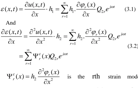
(3.1)And
2 2
2 2 2
2 2 1 2 1
( )
( , )
( , )
.
( )
j t r r r j t r r rx
x t
u x t
h
h
Q e
x
x
x
x Q e
(3.2) 2 2 2( )
( )
rr
x
x
h
x
is therth
strain modecorresponding to displacement mode
r( )
x
. Indeed,Q
1r, 2rQ
,h
1andh
2are obviously not the same and are dependent on location along the structure. Equation (3) is valid for thin short plate-like structures in which the shear factors are comparably small or negligible when loaded in their own planes.The strain mode can be evaluated by:
1. The strain modal transfer function of the vibration system is represented by
2 1
n
ir jr
ij
r r r r
H
k
m
j c
(4)Evaluating modal mass, modal stiffness, modal damping and mode shapes from the displacement mode analysis, the strain modes can be identified using equation (3).
From displacement-strain relationship, the strain modes of the transverse vibration of the beam could be estimated by the central difference solution for equation (3) given by equation (5), though with low accuracy:
2
( 1) ( 1) ( 1)
2 2
2
r k r k rk r k
rk
x
x
(5)Here,
k
is the number of discrete points along the structure,
x
is the finite distance between adjoining discrete points, and
r is ther
th
strain mode corresponding to the displacement mode
r( )
x
.III. DAMAGECRITERIA
Changes in strain modes reflect damage, however, their measurement and evaluation in large engineering structures is technically a formidable task. Time-displacement responses measured at widely and densely scattered points on the structure are considered for the following analysis.
The strain response under the action of an external force
( , )
(
o).
j tf t x
x
x
e
is:.
).
(
)
,
(
1
r t j rr
x
Q
e
x
x
t
(6)
If the strain responses of an intact and a damaged structure are known, then the difference in the two;Z ( , )t x d( , )t x represents damage. (The subscript d indicates “of damaged structure” hereinafter). On the premise of equation (3), strain response is a linear combination of its modes. Therefore, sudden local changes in strain modes at damage locations will result into a local change in the corresponding responses; that is,
0 1
( , )
( ).
x L
j t
d d r d r
x r
t x
x Q e
x
(7)As a result, a partial derivative of strain response with respect to the spatial variable
x
, would reflect the pertinent change of strain, specifically1
( , )
( ).
j td r d r
r
t x
x Q e
x
(8)In view of equations (7-8) and the above considerations, the following functions are proposed for a damage criterion:
1
0
1
( )
( , )
T
Z x
t x dt
T
(9.1)2
0
1
( )
(
, )
( , )
T
Z x
x
h t
x t dt
T
(9.2)To circumvent direct measurement, the transverse displacement of a vibrating beam structure has been used to compute
from measured displacement signals using equation (10), a solution strategy, specially derived to limit computation errors in solving the equation2 2
( , )
( , )
.
x t
u x t
h
x
x
(10)IV. SIMULATIONANDANALYSIS A FEM program in Matlab to demonstrate damage detection in a cantilever beam by the proposed criterion was developed;
x
0
, free end;x
100
fixed end, with dimensions L=1 m; W=0.025 m, H=0.0095 m, and material constantsE
2.0 10
11Pa, μ=0.33, ρ=7850kg/m3. The cantilever was meshed into 100 elements and the damage in an element modeled by a decreased width. The degree of damage is hereby represented by the ratio λ=w/W.V. DISPLACEMENTANDSTRAINMODAL ANALYSIS
Eigenvalues were analyzed for intact and damaged structures. Table 1 shows the natural frequencies for λ= 0.5 when the damaged element is varied from 10th to 90th element position by a step 10.
i
[image:2.595.47.287.126.280.2]Element Element i1 1 -i Element w W L
Table 1: Natural frequencies for a damaged beam, damage degree λ=0.5
Table 1 shows that, the changes in natural frequencies are comparatively small; the change in first frequency is less than 0.2 Hz. Non-dimensional strain modes for known displacement modes were computed based on equation (3) for the case of a constant a
h
as a first order derivative of displacement modes with respect tox
. Figure 2 (a)-(c) shows displacement and strain modes. There is no discernible damage symptom in the displacement modes, nonetheless, peaks appear at the damage location in the strain mode curves. Results in Fig 2c were experimentally obtained on a SLDV. [image:3.595.42.260.84.233.2]Figure 2 shows the differences in first strain modes of undamaged and damaged beam for λ=0.5. The results show how the peak heights vary with the damage location between elements 10 through 90.
Fig. 2: Displacement and strain modes for undamaged and damaged beams at element 60
[image:3.595.34.283.447.722.2](c)
Fig.2: Displacement modes for undamaged and damaged beams at element 60
VI. RESPONSEANDANALYSISOFCRITERIA The cantilever was excited by a harmonic force ( ) sin( )
f t A t at the free end and the displacement response computed by FEM. The strain response was evaluated by equation (3). The time interval [0, 0.4s] with step 0.001s was used. Figures 4-5 show displacement and strain responses at node 50, whereas figures 6-7 show displacement and strain mode responses at node 100. Using the responses, the damage criteria
z
1 andz
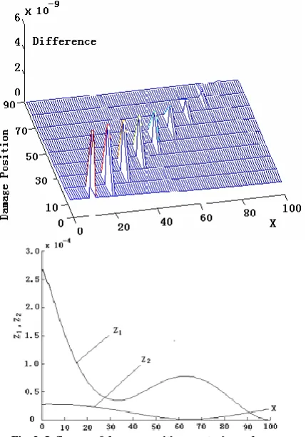
2 were evaluated for various damage locations. Figure 8 illustrates1
z
andz
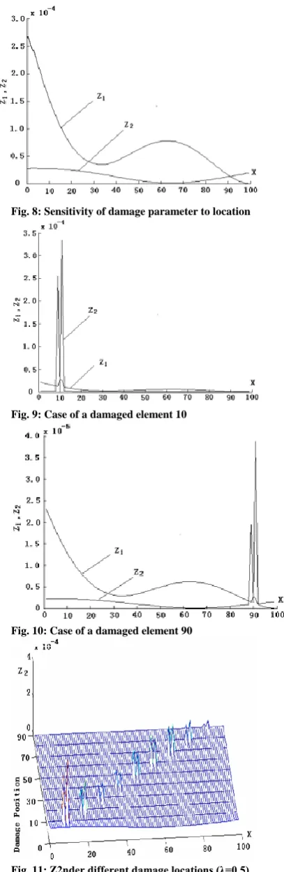
2as smooth curves in an intact beam. Figures 8-10 depict scenarios of the damage at elements 10 and 90 respectively.In figures 9 and 10, there exist peaks at the damage sites.
z
1 andz
2 has one peak and two peaks respectively centered at damage sites. This property could hold a premise for isolating a real damage from noisy data.Figure 11 shows a
z
2 curve when damage position is varied from 10 to 90 in a step of 12; the peaks’ sites well coincide with the damage location. The curve reflects sensitivity ofz
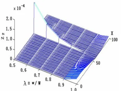
2 to damage location. Comparing Figures 3 and 12, it is obvious that the abrupt change in strain modes results in the peaks ofz
2. Figure 12 showsz
2 for increasing degree of damage with a fixed damage location, i.e. sensitivity ofz
2 with respect to degree of damage.z
2Increases exponentially with linear increment in the damage degree.
Fig. 3: Influence of damage position on strain mode
Mode 1st 2nd 3rd 4th
[image:3.595.307.522.454.761.2]Fig. 4: Time displacement response at node 50
Fig. 5: Relative strain response at node 50 (damaged)
[image:4.595.67.505.33.684.2]Fig. 6: Displacement response at node 100 (damaged)
Fig. 7: Relative strain response at node 100
Fig. 8: Sensitivity of damage parameter to location
Fig. 9: Case of a damaged element 10
[image:4.595.307.511.47.674.2]Fig. 10: Case of a damaged element 90
Fig. 12: Under different degrees of damage (damaged element 60)
VII. CONCLUSION
A criterion based on derivative of displacement modes responses with respect to a spatial variable has been established by analysis for structural damage detection and its validity and properties demonstrated by numerical simulation. The two functions;
z
1 andz
2 reflect damage position and damage degree.z
2 is more sensitive to damage thanz
1. In the same damage condition,z
1 has one peak andz
2 has two. Only measured displacement response of the structure is sufficient for availability of the criterion. The measurement points for displacement response have to be sufficiently dense to curb on noise error in the strain responses evaluated as a second order derivative of displacement. The approach is good for plate-like structures loaded in their own planes when the shear factors are negligibly small.Further analysis of the proposed criterion for various cases of excitations; impact, random loading and identification of degree of damage by the author is underway.
ACKNOWLEDGMENT
The author acknowledges the Faculty of Engineering and Technology, Vaal University of Technology, South Africa, for facilitating this research.
REFERENCES
[1] L. Meirovich, 1986. Elements of vibration Analysis. New York: McGraw-Hill.
[2] G. M. L. Gladwell, 1986. Inverse Problems in Vibration. Amsterdam: Martinus Nijhoff Publishers.
[3] R.D Adams, P. Cawley, C. J. Pye and B. J. Stone, 1978. Journal of Mechanical Engineering Science, 20, 93-100. A vibration technique for non-destructively assessing the integrity of structures.
[4] A. D. Dimarogonas, and C.A. Papadopoulos, 1983. Journal of Sound and Vibration 91, 583-593. Vibration of Cracked shafts in bending. [5] Cawley and R. Ray, 1988. Transactions of ASME 100, 366-370. A
comparison of the natural frequency changes produced by cracks and slots.
[6] R. D. Adams and P. Cawley, 1979. Journal of Strain Analysis 14, 49-57. The location of defects in structures from measurements of natural frequencies.
[7] H. Sato, 1983. Journal of Sound and Vibration 89, 59-64. Free vibration of beams with abrupt changes of cross-section.
[8] Young Shin, Lee, Myung Jee, Chung; A study on crack detection using eigenfrequency test data, Computers & Structures, Vol. 77 (2000), p. 327.
[9] D. Liu, H. Gurgenci and M. Veidt: Crack identification in hollow section structures through coupled response measurements. Proceedings of 19th IMAC, Hyatt Orlando Kissmmee, Florida, USA, February 5-8, 200l, pp 199-206.
[10] Myung Keun, Yoon, Dirk Heider, John. W. Gillespie Jr; Local damage detection using a global fitting method on mode shape data. Proceedings of 19th IMAC, Hyatt Orlando Kissmmee, Florida, USA, Feb 5-8,200l, pp 231-237.
[11] L. H Yam, T.P Leung, D.B. Li and K. Z. Xue; Theoretical and Experimental Study of Modal Strain Analysis, Journal of Sound and Vibration, 1996, 191(2), 251-260.
[12] Y. Y. Li, L. Cheng, L. H. Yam, and W. O. Wong; Identification of damage locations for plate-like structures using damage sensitive indices: Strain modal approach, Journal of Computers & Structures, Vol. 80 (2002), pp. 1881.
[13] B. S. Kim, and H. K. Kwak; A study of crack detection in plates using strain mode shapes, Proceedings of 19th IMAC, Hyatt Orlando Kissmmee, Florida,USA, Feb 5-8,200l, pp 1212-1218.
[14] Shen-En Chen, Suhas Venkatappa, John Moody, Samer Petro and Hota GangaRao, A Novel Damage Detection Technique Using Scanning Laser Vibrometry and a Strain Energy Distribution Method, Materials Evaluation, 2000, December, pp.1389-1394.
[15] A. Z. Khan, A. B. Stanbridge, and D. J. Ewins; Detecting damage in vibrating structures with a scanning LDV, Optics and Lasers in Engineering 32(2000) 583-592.
[16] Quan Wang, and Xiaomin Deng, Damage detection with spatial wavelets, International Journal of Solids and Structures, 1999, 36(23), 3443-3468.
[17] Alfayo Anyika Alugongo, Chen Jin; A Frequency-Mode Based Approach for Cracked Beam Identification, Proceedings of the third Asia Pacific Conference on Systems Integrity and Maintenance, Queensland University of Technology, Queensland, Australia, Sept., 25-27, 2002, pp. 28-35.