Electrodiffusion Model Simulation of Ionic Channels: 1D Simulations
CARL L. GARDNER∗
Department of Mathematics and Statistics, Arizona State University, Tempe, AZ 85287, USA gardner@math.asu.edu
WOLFGANG NONNER†
Department of Physiology and Biophysics, University of Miami Medical Center, Miami, FL 33136, USA wnonner@chroma.med.miami.edu
ROBERT S. EISENBERG‡
Department of Molecular Biophysics and Physiology, Rush Medical Center, Chicago, IL 60612, USA beisenbe@rush.edu
Abstract. The drift-diffusion (Poisson-Nernst-Planck) model is applied to ionic channels in biological membranes plus surrounding solution baths. Simulations of the K channel in KCl solutions using the TRBDF2 method are presented which show significant boundary layers at the ends of the channel. The computed current-voltage curve for the K channel shows excellent agreement with experimental measurements.
Keywords: biological channels, diffusion models, ion transport
1. Introduction
Biological cells exchange chemicals and elec-tric charge with their environments through ionic channels—protein tunnels filled with ions and water— in the cell membrane walls (see Ref. [1] for a com-prehensive introduction). Signaling in the nervous sys-tem, coordination of muscle contraction including the pumping action of the heart, and ion transport in every cell and organ are carried out through ionic channels.
We consider a flow of positive and negative ions (cations and anions) in water in a channel (or pore) plus surrounding baths in an electric fieldE(x,t) against a background of charged atoms on the channel protein. The discrete distribution of charges is described by
con-∗Research supported in part by DARPA under grant BAA 01-07. †Research supported in part by NIH/NSF under grant R01 GM
67241-01.
‡Research supported in part by DARPA under grant BAA 01-07.
tinuum [2–4] particle densitiesni(x,t) for the mobile
ions (i =K+, Cl−, Na+, Ca++, . . . ) and N(x) for the charged atoms (“doping” in the language of semicon-ductor device physics) of the protein. The permanent fixed charge densityN may include both positive and negative charges, but the protein is predominantly neg-atively charged. Note thatN vanishes by definition in the baths.
In the experimental setup, a voltage biasVis applied across the channel plus baths by means of a voltage clamp. The channel transit time for an ion is on the order of 10 ns, while experimentally the finest temporal resolution of currents is on the order of 10–50µs, so experimental measurements are averaging over 1000– 5000 ions.
∂ni
∂t + ∇ ·ji=0 (1)
ji =ziµiniE−Di∇ni (2)
∇ ·(∇φ)=eN−
i
qini, E= −∇φ (3)
whereeis the proton charge,is the dielectric coeffi-cient, and where for each ion speciesi,jiis the number
current density (particle flux),qiis the ionic charge (for
example,qCa = +2e),zi = qi/e,µi is the mobility
coefficient, andDiis the diffusion coefficient. The total
electric current density (charge flux) is
jelec=
i
qiji. (4)
The physical parameters,µi, andDiare functions of
x.
The drift-diffusion equations form a parabolic/ elliptic system of PDEs: the transport equation (1) (withjispecified by Eq. (2)) is parabolic and Poisson’s
equation (3) is elliptic. Thus the boundary conditions for bothniandφare Dirichlet and/or Neumann.
As an example of a physiologically important chan-nel, we will focus our attention here on the K channel il-lustrated in Fig. 1 (the KcsA channel structure shown is derived from X-ray crystallography). K channels play a central role in electrical signaling in the nervous sys-tem. A typical nerve cell has hundreds of thousands of K channels.
[image:2.595.327.491.156.318.2]The K channel isselective; i.e., it allows K+ions to flow freely between the interior and exterior of the cell, but not (for example) Na+or Ca++ions. (Cl−ions are prevented from flowing through the K channel by the electrostatic field in the channel.) We will model the channel plus regions of the bath illustrated in Fig. 2 out to a distance where the ion densities and the elec-trostatic potential take on their asymptotic values in
Figure 1. K channel, membrane, and interior and exterior baths. the baths:ni = Nbi,φ = 0 at the left boundary, and
ni = Nbi,φ = V at the right boundary (see Figs. 4
and 5). The overall region is electrically neutral. The diffusion and mobility coefficients of the mobile ions are typically much smaller in the channel than in the baths (see Table 1).
Boundary conditions should not be applied at the ends of the channel, due to the fact that boundary layers in ionic charge density and in the electrostatic poten-tial develop there, as illustrated in Figs. 4 and 5. The ionic charge densities and the electrostatic potential reach their equilibrium far-field values approximately two Debye lengths into the baths (the Debye lengths for K+and Cl−are on the order of 1 nm in the baths). In the one-dimensional approximation to the K chan-nel problem with the chanchan-nel 3.5 nm long, the baths are represented by conical funnels (Fig. 3) extending 5 nm into the baths and opening at 45◦angles on either side of thezaxis (the opening angle has only a weak effect on the computed solution and total current). The funnels should be wide enough so that the impedance of the baths to the ion flow is very small compared to the impedance of the channel.
The drift-diffusion equations (1)–(3) can be written in the form
∂ni
∂t + ∇ ·(ziµiEni)= ∇ ·(Di∇ni) (5)
jelec=
i
qi(ziµiniE−Di∇ni) (6)
∇ ·(∇φ)=eN−
i
Figure 2. Diagram of computational region for channel, membrane, and baths. Boundary condition types are labeled in italics for the 3D problem.
Figure 3. Diagram of 1D computational region for channel and bath funnels.
The boundary condition (BC) types in Fig. 2 are defined by
ni =Nbi, φ=0 (interior bath far-field BC)
ni =Nbi, φ=V (exterior bath far-field BC)
ni =Nbi, ∂φ
∂r =0 (ambient bath BC) ˆ
n· ∇ni =0, nˆ· ∇φ=0 (no-flux BC)
where ˆnis a unit normal vector to the boundary. The channel problem illustrated in Fig. 1 has an ap-proximate cylindrical symmetry; in other words, the solutionni,φdepends to an excellent approximation
only onrandz, where cylindrical coordinates are de-noted by (r, θ,z), with thezaxis along the length of the channel. (With cylindrical symmetry, no-flux boundary conditions are imposed along thezaxis as well.) If we neglect the dependence ofniandφonrin the channel
and the near bath regions, which is a good approxima-tion if the cross secapproxima-tional area A(z) varies slowly with z(this is the standard approximation used in the
anal-ysis and simulation of nozzle flow in gas dynamics), then we obtain a one-dimensional approximation to the channel problem.
In our first model, we will treat just a one-dimensional approximation of the channel plus fun-nels opening into the baths on either side. Future sim-ulations will extend the simsim-ulations to two and three dimensions.
To write down the 1D equations, recall that the def-inition of the divergence of a vector fielduis
∇ ·u= lim
V→0
1 V
∂Vu·nˆda (8)
whereV is a volume centered aroundx with bound-ing surface∂V. Foru(x)= u(z)ˆez andV = A(z)z,
Eq. (8) reduces to
∇ ·u= lim
z→0
1
Az[u(z+z)A(z+z)−u(z)A(z)]
= 1
A
∂
[image:3.595.156.439.317.443.2]A∂z ∂z i ∂z
φ(0)=0, φ(L)=V (12)
where the simulation region which includes the chan-nel plus baths runs from 0 to L=lc + 2lb and
ni(x,t)=ni(z,t),φ(x,t)=φ(z,t). For both the
ellip-tic Poisson’s equation (12) and the parabolic transport equation (10), Dirichlet boundary conditions onφand ni are imposed at the left and right boundaries.
Note that in this 1D approximation, the current den-sity (and thus the ion velocity) and the electric field will lie in thezdirection. To simplify the mathematical analysis of the 1D model (10)–(12), the cross sectional areaA(z) may be set to a constant in the channel itself, but not in the baths.
The drift-diffusion model for a spherically symmet-ric problemni(x,t)=ni(r,t),φ(x,t)=φ(r,t), where
spherical coordinates are denoted by (r, θ, ϕ), takes ex-actly the same form as Eqs. (10)–(12) withzreplaced byr. Since the equipotential surfaces and the level set curves of ni are normal to the cell membrane walls
(since there is no ion flow through the walls and since to a good approximation there is no electrical flux through the walls), the solution in the baths near the channel openings may be modeled as approximately spheri-cally symmetric [5] for a moderate radial distance into the baths. Then, as long as the flow and electric field lines remain approximately radial in the baths near the channel openings, Eqs. (10)–(12) withzreplaced byr may be used with the cross sectional areaA(r) now the surface area of spherical shells starting and ending at a cell membrane wall. The 1D cylindrically symmetric solution in the channel is “patched” onto the spheri-cally symmetric solution in the channel opening and the bath. Both the assumption of spherical symmetry and the patching together of solutions introduce errors. The validity of this approximation will be tested against 2D cylindrically symmetric simulations.
jelec= i
qi(ziµiniE−Di∇ni) (14)
∇ ·(∇φ)=eN−
i
qini, E= −∇φ. (15)
In 1D, the steady-state drift-diffusion equations are
∂ ∂z
A
ziµiEni−Di ∂ni
∂z
=0,
ni(0)=Nbi =ni(L) (16)
jelec=
i
qi
ziµiniE−Di∂
ni ∂z (17) 1 A ∂ ∂z A∂φ ∂z
=eN−
i
qini, E= −∂φ ∂z,
φ(0)=0, φ(L)=V. (18)
4. Numerical Methods for Electrodiffusion
Variables ni and φ are defined at gridpoints
0,1, . . . ,N, while jandEare defined at midpoints of grid cells−1/2,1/2,3/2, . . . ,N+1/2. Givennn
i and
Enat timeleveln, a timestep consists of two parts. (i)
First we solve the transport equation (10) fornni+1with
E = En. (ii) Then we solve Poisson’s equation (12)
forEn+1usingnn+1
i on the right-hand side.
We use the implicit, L-stable TRBDF2 [6,7] (trape-zoidal rule/second-order backward difference formula) method for the time-dependent drift-diffusion trans-port equation, which allows simulations to use large timesteps. TRBDF2 is a one-step second-order ac-curate method; the timestep is adjusted dynamically by a divided difference formula estimate of the local error.
then takes the form—(1) TR step ofγ t:
un+γ −γtn 2 f
n+γ =
un+γtn 2 f
n
and (2) BDF2 step oft:
un+1−1−γ 2−γtnf
n+1
= 1
γ(2−γ)u
n+γ − (1−γ)2 γ(2−γ)u
n.
With the electric field frozen while updating the trans-port equation, f(u) is linear. We take the usual value
γ = 2−√2 which minimizes the magnitude of the local error.
For Poisson’s equation we use a tridiagonal direct solver.
5. Simulation of the K Channel
We will consider here the flow of K+ ions (in water) through a channel of diameter 1 nm and length 3.5 nm. For various sections of the K channel and surround-ing KCl baths, the lengths l, background permanent charges Q on the protein which go into N, dielec-tric constants, mobility coefficientsµ, and diffusion coefficients D are given in Table 1. The mobilities and diffusion coefficients satisfy the Einstein relation e D/µ=kBT0≈1/40 eV.
[image:5.595.316.519.159.247.2]The bath concentrations for the positive and nega-tive ions are 0.15 molar =9×1019 cm−3. We also
Figure 4. Simulation of the K+densitynK(red, dark) and Cl−densitynCl(cyan, light) forV = −100 millivolts. The protein permanent
charge densityNis shown in blue (dashed). The vertical scale is log10of density/(1021cm−3).
Table 1. Lengthslin nm, background permanent chargesQ on the protein, dielectric constants, mobility coefficientsµin 10−5cm2/(V s), and diffusion coefficientsDin 10−5cm2/s.
Region l Q µ D
Baths 5 0 80 60 1.5
−4egroup 0.2 −4e 80 16 0.4
Nonpolar 1.1 0 4 16 0.4
Central cavity 1 −e/2 30 16 0.4
Filter 1.2 −3e/2 30 16 0.4
assume that there are equal concentrations of ions in-side and outin-side the cell membrane, so that no cur-rent flows when V = 0. The baths are modeled by funnels which open from the channel cross sectional area A = π(1 nm/2)2 at the channel opening out to
A = π(11 nm/2)2 at 5 nm into the baths. These
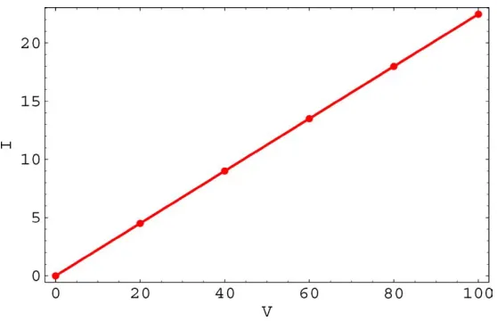
pa-rameters give a linear current-voltage curve with a cur-rent of 22.5 picoamperes at a bias of−100 millivolts (Fig. 6). Experimentally the current at−100 millivolts is on the order of 20–30 picoamps for this type of channel.
[image:5.595.159.439.525.701.2]Figure 5. Simulation of electrostatic potential in millivolts forV= −100 millivolts.
Figure 6. Current in picoamperes vs. voltage in millivolts.
−4echarge group and about one K+ ion on average in the filter. (The drift-diffusion model predicts about 1/15 Cl− ion on average flowing in the channel; this is a reasonable continuum approximation to the actual biological picture of discrete ions in which Cl−ions are excluded by the electrostatic field from the K channel.) The simulated region of channel plus baths is electri-cally neutral overall.
AtV = −100 millivolts, the current I+carried by the K+ ions is 22.2 picoamps, while the current I− carried by the Cl−ions is 0.3 picoamps. Many exper-imentalists believe that no current should be carried by the Cl− ions; however measurements only restrict I−<I/20.
6. Conclusion
[image:6.595.159.438.337.517.2]value of 200 millivolts at which the lipid membrane begins to break down from charge arcing and the chan-nel protein itself is deformed by the electrostatic forces. Future work will include simulations for the 2D cylindrically symmetric approximation to the channel plus baths, and a separate model for gating and gating charge movement.
References
1. B. Hille, Ionic Channels of Excitable Membranes (Sinauer, Sunderland, MA, 1992).
2. R.S. Eisenberg, M.M. Klosek, and Z. Schuss, “Diffusion as a chemical reaction: Stochastic trajectories between fixed concen-trations,”Journal of Chemical Physics,102, 1767 (1995).
3. W. Nonner, D. Chen, and R.S. Eisenberg, “Anomalous mole frac-tion effect, electrostatics, and binding,”Biophysical Journal,74, 2327 (1998).
4. W. Nonner and R.S. Eisenberg, “Ion permeation and glutamate residues linked by Poisson-Nernst-Planck theory in L-type cal-cium channels,”Biophysical Journal,75, 1287 (1998). 5. D. Gillespie, W. Nonner, and R.S. Eisenberg, “Coupling
Poisson-Nernst-Planck and density functional theory to calculate ion flux,” Journal of Physics: Condensed Matter,14, 12129 (2002). 6. R.E. Bank, W.M. Coughran, W. Fichtner, E.H. Grosse, D.J. Rose,
and R.K. Smith, “Transient simulation of silicon devices and cir-cuits,”IEEE Transactions on Computer-Aided Design,4, 436 (1985).