Haemodialysis
See II / MEMBRANE SEPARATIONS / Dialysis in Medical Separations
Kidney Dialysis
See II / MEMBRANE SEPARATIONS / Dialysis in Medical Separations
Liquid Membranes
L. Boyadzhiev, Institute of Chemical
Engineering, Bulgarian Academy of Sciences, Sofia, Bulgaria
Copyright^ 2000 Academic Press
Introduction
The separation of solutes by means of liquid mem-branes is based on a simple and well-established idea: two completely miscible liquid phases, separated by a third liquid, immiscible with either of them, can exchange solutes, provided there is a difference be-tween their chemical potentials in the two phases and provided the intermediate liquid is able to transport them. In most cases the two miscible liquids, denoted hereafter as donor and acceptor phases, are aqueous solutions and the third (membrane) phase is an or-ganic liquid. The conRguration involving two organic solutions separated by an aqueous membrane is less popular.
The growing interest in the recovery and separation of solutes by means of liquid membranes may be related to the advantages of this separation method over the related separation operations}solid mem-branes and solvent extraction } as well as to the recent development of efRcient liquid membrane techniques and contactors.
The main advantage of liquid membranes over polymer ones is the higher Sux, owing to the very much higher diffusion coefRcients of solutes in liquids than in solids. Moreover, some liquid membrane techniques allow a convective diffusion regime in-stead of a molecular one, which also increasesSuxes. Another advantage of liquid membranes is the avail-ability of a great number of substances which, when added to the liquid membrane phase, increase selec-tivity.
A liquid}membrane process can be regarded as a combination of extraction and a stripping process, which take place simultaneously in the same device. In solvent extraction, both the extractant amount and the distribution coefRcient of the solute play essential roles for process efRciency, whereas in liquid membrane separation the selectivity is controlled by the kinetics of the transport process. In contrast to solvent extraction, in liquid membrane separation the amount of transferred solute is not proportional to the amount of the solvent used, in this case the membrane liquid. The relatively small amount of the latter permits the use of various highly efRcient and selective}even expensive}carriers.
Mechanisms of Solute Transfer
Like some of the solid}membrane separation methods, the difference between the chemical poten-tials of the solute in the donor and acceptor solutions controls the transport of the species. In other words, the concentration difference is the driving force.
There are various mechanisms for the selective transfer of solutes in the considered three-liquid-phase system. They can be divided into two groups: nonfacilitated and facilitated, or carrier-meditated, transfer mechanisms.
Figure 1 Basic transport mechanisms. (A) Simple nonfacilitated transport; (B) Simple uphill nonfacilitated transport; (C) facilitated uphill transport; (D) facilitated (coupled) co-transport; (E) facilitated (coupled) countertransport. See text for details.
a solute is accompanied by an equivalent transfer of one or more other solutes, it is designated as coupled transport. Depending on the direction of the accom-panying transfer, the mechanisms are called co-trans-port and countertransco-trans-port. Figure 1 illustrates the
Rve most popular transport mechanisms: (A) and (B) refer to nonfacilitated mechanisms, while (C)}(E) re-fer to facilitated mechanisms.
Nonfacilitated Mechanisms
Figure 1A shows the nonfacilitated transport of sol-ute A from the donor solution to the membrane liquid as a result of its solubility and the low concentration in the latter. From this phase, it is transferred to the acceptor phase again for the same reasons. This pro-cess continues until the chemical potentials of the solute, i.e. its concentrations in the donor and accep-tor solution, are equal. The selectivity of separation of solutes present in the donor solution mainly de-pends on the difference between their transfer rates, which in turn are related to their solubility in the membrane and, to a lesser extent, on the difference between their diffusion coefRcients. This rather simple mechanism is of no practical interest. An example is the separation of aromatic and aliphatic hydrocarbons using water as the membrane phase.
Figure 1B shows a second example of non-facilitated transport. The process differs from Fig-ure 1A in that the acceptor solution has a component B which is insoluble in the membrane; it reacts irre-versibly with solute A that permeates through the membrane. The reaction product AB is insoluble in
the membrane and cannot diffuse back to the donor solution. In some cases an enzyme plays the role of the reagent B, transforming transported solute into products which are insoluble in the membrane. The continuous consumption of A in the acceptor solution maintains its concentration in this phase at a low level, creating a sufRcient driving force to transfer the whole amount of A from the donor solution. The solute A in the form of the product AB can reach very high concentrations in the acceptor solution, which is generally of a smaller volume than the donor solu-tion. This transfer, apparently against the concentra-tion gradient, is known as a simple uphill transport and it has a real practical value. A typical example is the transfer of a phenol as a neutral solute which is soluble and thus permeable through the organic membrane phase. The acceptor phase is an alkaline solution that converts the phenol to an ionized salt which is not soluble or permeable through the mem-brane phase.
Facilitated Transport Mechanisms
Figure 2 Bulk liquid membrane contactors for laboratory use. (A) U-tube contactor (Schulmann bridge); (B) beaker-in-beaker contactor; (C) and (D) two cells separated by supported liquid membrane.
the membrane to the feed}membrane interface to bind a new portion of the solute A. Because of this shuttle mechanism, small amounts of the carrier C can transfer large amounts of the solute in the acceptor phase. An example is the recovery of nitric acid from dilute solution using a small amount of the carriers tributylphosphate or trioctylphosphine oxide. The adducts formed are unstable in strongly alkaline media (the acceptor solution), where the acid is neutralized and irreversibly converted into nitrate. In transport processes shown in Figure 1D, some-times called facilitated co-transport, the carrier C re-versibly forms an intermediate complex not only with the solute A but also with other (one or more) con-stituents of the donor solution. The complex ABC so formed is transported to the acceptor solution, where it reacts with another additive, D, by forming a more stable compound. The latter, like the reagent D, is insoluble in the membrane liquid. An example of this mechanism is the transport of silver which is selec-tively recovered from complex polymetallic nitrate solutions. The complex, transferred across the mem-brane, is formed by a silver cation, a nitrate anion and two molecules of the extractant triisobutylphosphine sulRde, selective for silver. In the acceptor solution, the complex is destroyed by ammonia. The chemical reaction in the acceptor phase yields ammonium ni-trate, the stable silver}ammonia complex and the regenerated carrier.
Figure 1E illustrates the third, probably most often used, facilitated transport mechanism, sometimes called facilitated countertransport. In this case, ions, initially present in the donor solution, are substituted
by other ions of the same type, present in a sufRcient amount in the acceptor solution. This is actually an ion exchange process in which the ion-exchanging agent, the carrier C, transports in one direction one type of ion and in the opposite an equivalent amount of substituent. A typical example for this transfer is the recovery of some divalent metal cations, e.g. Cu2#, from neutral or slightly acidic aqueous
solu-tions by means of oleophilic chelating oximes. The latter transfers the metal ions to the strongly acidic acceptor solution and returns protons according to the scheme:
Me2##2HR0MeR2#2H#
The equilibrium conditions at the two interfaces, con-trolled by the pH values of the aqueous phases, are chosen so that the metal}organic complex is the stable species at the donor}membrane interface, while free cations exist at the membrane}acceptor interface. This type of process is of great signiRcance for hydrometallurgy and for the removal of heavy metals from industrial efSuents.
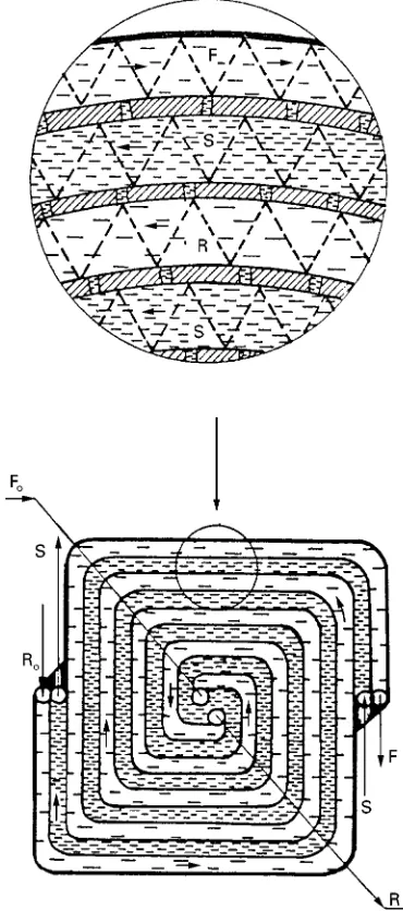
Figure 3 Spirally wound supported liquid membrane module. R, Acceptor solution; F, donor solution.
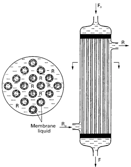
Figure 4 Hollow fibre supported liquid membrane module. R, Acceptor solution; F, donor solution; S, membrane liquid.
membrane and in the bulk of the acceptor solution. The reader may Rnd further information in the Fur-ther Reading section.
Liquid Membrane Techniques
The main reason for the limited large scale appli-cation of liquid membrane processes is the lack of efRcient equipment providing simultaneously large contact areas and high Suxes between the phases without deterioration of the membrane over time causing intermixing of the donor and acceptor phases. The realization of stable membranes is an extremely difRcult task.
In general, liquid membrane techniques can be divided into two groups: techniques in which there is no dispersion of phases and techniques with at least one dispersed phase. The Rrst group includes bulk liquid membranes and the supported liquid mem-branes, as well as some recent techniques combining elements from both techniques. The second group is mainly represented by the emulsion liquid membrane technique.
Methods Without Phase Dispersion
Simple bulk liquid membranes Several simple con-tact devices designed for studies of liquid}membrane processes are shown inFigure 2. In all, there is a com-mon compartment for the membrane liquid. The other contactor space is divided into two compart-ments, one for the donor solution and the other for the acceptor solution. The interface between the membrane liquid and the other two solutions is free (A, B) or immobilized (C, D) by a solid porous mem-brane. TheRrst device (A) is known as the Schulmann bridge. Devices of the type shown in Figure 1A and B are limited to laboratory experiments, but the
con-tactors shown in Figure 2C and D Rnd a broader application. In these devices, the membrane liquid permeates a porous membrane, which separates the donor and the acceptor solutions. In modiRcation (D), a cylinder with an attached porous barrier rotates and stirs the donor and acceptor phases, reducing or eliminating the mass transfer resistances in these two phases. The type of device depends on whether the membrane liquid is heavier or lighter than the other two solutions.
Supported liquid membranes The laboratory con-tactor shown in Figure 2C is the prototype of sup-ported liquid membrane contactors. In these devices the membrane liquid Rlls the pores of a 25}100m thick porous membrane containing pores 0.01}10m in diameter. The membrane is usually made of polypropylene, polysulfone or another oleophilic polymer.
[image:4.568.297.513.408.684.2]Figure 5 Spiral-type flowing liquid membrane module. R, Acceptor solution; F, donor solution; S, membrane liquid.
2000}10 000 m2/m3. In such modules, one of the aqueous phases Sows in the lumen of the hollow
Rbres, while the otherSows outside theRbres and the pores of theRbre walls areRlled with the membrane liquid.
The insigniRcant amount of membrane liquid re-quired in these modules (10 cm3per 1 m2 interface), often pointed out as a major advantage, is actually the chief drawback of supported liquid membrane contactors, causing their operational instability and short life. The life of the expensive modules is shortened by the inevitable solubility of the mem-brane liquid in the donor and acceptor phases, by its washing out or by emulsiRcation caused by the pres-sure difference on both sides of the membrane, the lateral shear force, and the change of support wetta-bility with time. In spite of numerous design improve-ments, e.g. periodic or continuous reimpregnation of the membrane and partial or total gelation of the membrane liquid, this technique has not been used in industrial applications.
This instability forced researchers as early as in the 1980s to look for other solutions. The combination of this technique with stable bulk liquid membranes yielded the bulk-supported liquid membranes.
Flowing liquid membranes and contained liquid membranes In these two variants of the bulk-supported liquid membrane group, as well as in numerous subsequent modiRcations, the membrane liquid not onlyRlls the pores of two closely spaced porous supports separating the donor and acceptor phase, but also the space between them, as shown in Figures 5and6. Figure 5 shows a device introduced by Teramoto et al., called the Sowing liquid membrane: the spirally wound module contains one additional layer and one additional porous barrier (Figure 5) in comparison with the analogous sup-ported liquid membrane module, shown in Figure 3. Between the two, separated by porous support spacers,Sows the membrane liquid, which alsoRlls the pores of the support which are preferentially wetted by it.
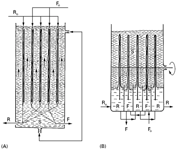
In contained liquid membranes, a technique pro-posed by Sirkar et al. in the late 1980s, the donor phaseSows in the lumen of a part of the capillaries, while the acceptor phaseSows in the lumen of the rest of them. As Figure 6 shows, the membrane liquid
Rlling the space outside the hollowRbres can also be set in motion. When the hollow Rbre material is wetted by the membrane liquid, the pores are Rlled with it. In the reverse case, they are Rlled with the other two phases. The module shown in Figure 6, in which the inlets and the outlets of the feed and accep-tor phases are located in one end of the module case,
permits free elongation of theRbre package caused by the swelled membrane liquid.
The latter two membrane techniques provide sig-niRcantly longer life of the contactors, as the inevi-table losses of membrane Suid are compensated by the larger liquid volume. However,Suxes are lower because of higher mass transfer resistance due to the second porous supportRlled with immobilized liquid and the two additional diffusion boundary layers in the same phase. This drawback is, however, off-set by the longer membrane life.
Figure 6 Contained liquid membrane contactor. R, Acceptor solution; F, donor solution; S, membrane liquid.
[image:6.568.141.428.439.683.2]Figure 8 Separation by emulsion liquid membranes. 1, Emulsion preparation (step 1); 2, feed treatment with the emulsion (step 2); 3, break-up of enriched emulsion (step 3). R, Acceptor solution; F, donor solution; S, membrane liquid.
liquid contacts with the acceptor liquid. The mem-brane liquid circulates between the two devices. This technique, bearing the name two-module hollowRbre supported liquid membranes, differs little from the arrangement in a conventional extraction-stripping unit operation.
Liquid Vlm pertraction The technique known as liquidRlm pertraction attempts to combine the ad-vantages of bulk liquid membrane and supported liquid membrane. In the process all three liquids are in motion and the interfaces between the phase pairs are not immobilized, so that the transport rate in all stages of the transfer process is controlled by convec-tive transport instead of the much slower molecular diffusion.
Two devices utilizing this technique are schemati-cally presented inFigure 7. In theRrst one, called the
fallingRlm pertraction, shown in Figure 7A, the do-nor and acceptor solutionsSow down the surface of alternating vertical supports. The spaces between the opposite supports, covered by Rlms of donor and acceptor liquids, respectively, areRlled with the mem-brane phase,Sowing countercurrent to the other two. By independent control of theSow rates of the feed and acceptor phases, a signiRcant solute accumula-tion in the acceptor soluaccumula-tion can be achieved.
Figure 9 Two-compartment pulsating column. Applied pulsa-tions, D, exchange the membrane liquid S between central and annular compartments across the porous wall. R, Acceptor solu-tion; F, donor solusolu-tion; S, membrane liquid.
The advantages of these two techniques consist in the considerably larger Suxes per unit interface and in their practically unlimited life. However, the rather low ratio between the contact interface and the bulk of the solution neutralizes, theRrst advantage.
Methods with Phase Dispersion
Emulsion (surfactant) liquid membranes Emulsion liquid membranes wereRrst described in 1971 by Li in a paper dealing with the separation of aromatic and aliphatic hydrocarbons by stabilized dispersion of three liquids: the above-mentioned mixture, water and an inert hydrocarbon as a recipient phase. This technique, known as emulsion (or surfactant) liquid membranes, was the Rrst pertraction technique de-veloped to industrial scale.
As the name implies, the three-phase system is stabilized by an emulsiRer, added to the membrane liquid, in some cases its concentration in the mem-brane liquid reaches 5% or more. The acceptor solu-tion is dispersed as Rne (2}20m) droplets in the membrane phase. The thick emulsion, stabilized by the emulsiRer, is dispersed in its turn in the donor solution as globules of 1}2 mm diameter and the resulting dispersion is intensely stirred for several minutes. During this contact time, the solutes, which are more soluble in the membrane phase, are transfer-red from the donor phase to the intermediate phase and from there to the encapsulated acceptor solution. This transfer is very fast due to the large contact areas. After termination of the second (main) process step and dispersion settling, the enriched emulsion is separated and subjected to chemical, thermal or, most often, high voltage electrocoagulation, which breaks the emulsion into two phases. The separated mem-brane liquid phase is fed back for a new cycle of the process and the enriched acceptor solution phase is subjected to further treatment. The scheme in Fig-ure 8illustrates this three-stage batch process which in some modiRcations is carried out as a continuous process. In this process, the recovery efRciency and the separation selectivity are controlled by the trans-fer kinetics, i.e. by the diftrans-ference in the transtrans-fer rates of the individual solutes. As these rates depend on a great number of factors, for each case there is a speciRc optimum contact time, which can only be determined experimentally. A shorter than optimum contact time results in a lower solute recovery, while a longer contact time reduces selectivity and recovery efRciency. If the emulsion is too stable, this causes problems related to its break-up in the third process step. Irrespective of these drawbacks, the emulsion liquid membrane technique is most often investigated and practically applied.
Other techniques with phase dispersion In addition to the disadvantages listed above, the added
emulsi-Rer contaminates both the donor and acceptor phases, as in some cases its solubility in these phases exceeds that of the membrane liquid itself or of the carrier added. To avoid using surface active sub-stances, other techniques with phase dispersion were recently proposed, two of which are illustrated inFigures 9and10.
Figure 10 Combination of hollow fibre supported liquid membranes with the emulsion technique in which a nonstabilized phase R dispersed in phase S emulsion flows inside the hollow fibres.
two aqueous feed and acceptor phases are fed into the top of the central and annular space, respectively, as droplets of about 1 mm diameter. The porous Rlter tube does not allow intermixing of the droplets of the two aqueous phases. The aqueous droplets should be small enough to guarantee sufRcient residence time of the corresponding phase in the contractor, but not too small that it penetrates into the other compartment.
The second arrangement avoiding the use of sur-face active substances is shown in Figure 10. The technique is a combination of hollowRbre and emul-sion liquid membrane techniques without using an emulsiRer for dispersion stabilization. The accep-tor/membrane-phase emulsionSows in the lumen of porous capillaries wetted by the membrane liquid,
Rlling their pores. Evidently, no intense mass transfer is possible with this technique, irrespective of the continuous wash-out of the membrane liquid by the acceptor solution dispersed in it. This drawback is, however, again compensated for by the great number of hollowRbres used and by the recirculation of the intracapillary dispersion.
Application Areas
The liquid membrane processes described above are in principle highly efRcient chemical pumps selective-ly separating and concentrating valuable solutes. These processes have potential applications in a
num-ber of industrial areas, e.g. hydrometallurgy, elec-troplating and galvanic technologies, chemical and pharmaceutical industries. One of the most promising applications is in biotechnology, where pertraction, can be integrated with the basic bioprocess in order to increase process efRciency.
A very attractive feature of pertraction processes is their low investment, and in particular, their opera-tional costs. Being a membrane operation, the separ-ation does not involve phase transitions and therefore power consumption is very low. However, unlike solid membrane separations, the costs of lost mem-brane liquid and the puriRcation of treated solutions sometimes required additionally contribute to the process costs.
The Further Reading section lists titles containing more information on various pertraction systems studied in the last 25 years.
See also: I/Membrane Separations. II / Flotation: Flota-tion Cell Design: ApplicaFlota-tion of Fundamental Principles.
Further Reading
Araki T and Tsukube H (eds) (1991)Liquid Membranes: Chemical Applications. Boca Raton, FL: CRC Press. Bartsch RA and Douglas Way J (eds) (1996). Chemical
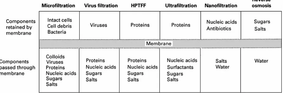
Figure 1 Classification of pressure-driven membrane processes showing typical bioprocessing applications.
Boyadzhiev L (1990) Liquid pertraction or liquid mem-branes}state of the art.Separation Science and Techno-logy25: 187.
Boyadzhiev L and Lazarova Z (1994) Liquid membranes (liquid pertraction). In: Noble RD and Stren SA (eds) Membrane Separation Technology. Principles and Applications, pp. 283}352. Amsterdam: Elsevier. Drioli E and Nakagaki M (1986)Membranes and
Mem-brane Processes. New York: Plenum.
Ho WSW and Sirkar KK (eds) (1993) Membrane Hand-book. New York: Van Nostrand Reinhold.
Li NN (1971) Permeation through liquid surfactant membranes.American Institute of Chemical Engineers Journal17: 459.
Noble RD and Douglas Way J (eds) (1996)Liquid Mem-branes. Theory and Application. American Chemical Society Symposium Series no 347. Washington, DC: American Chemistry Society .
Zhang R (ed.) (1984) Separation Techniques by Liquid Membranes (in Chinese). Nanchang: Jiangxi Renmin.
Membrane Bioseparations
A. L. Zydney, University of Delaware, Newark, DE, USA
Copyright^ 2000 Academic Press
Membrane processes are particularly well suited to the separation and puriRcation of biological mol-ecules since they operate at relatively low tempera-tures and pressures and involve no phase changes or chemical additives. Thus, these processes cause mini-mal denaturation, deactivation and/or degradation of highly labile biological cells or macromolecules. Al-though essentially all membrane processes (Figure 1) have been used for bioseparations, the greatest inter-est has been in the application of the pressure-driven processes of ultraRltration (UF) and microRltration (MF). UltraRltration membranes have pore sizes be-tween 1 and 50 nm and are used for protein concen-tration, buffer exchange, desalting, clariRcation of antibiotics and virus clearance. There is also growing interest in the use of ultraRltration for protein puriR -cation using high performance tangentialSowR ltra-tion (HPTFF). MicroRltration membranes have a pore size between 0.05 and 10m and are thus used
for initial clariRcation of protein solutions, cell harvesting and sterileRltration. In addition, ultraR l-tration and microRltration of blood are used for the treatment of a variety of metabolic and immunolo-gical disorders.
The development of membrane processes for bio-separations is very similar to the design of membrane systems for nonbiological applications. However, there are some important differences including:
1. increased concerns about deactivation or de-naturation of biological molecules and cells 2. very high value (on a per unit mass basis) of most
biological products (particularly recombinant therapeutic proteins)
3. tendency of biological macromolecules and cells to cause signiRcant fouling of both ultraRltration and microRltration membranes
4. critical importance of validation and integrity test-ing in bioprocesstest-ing applications