Abstract— Magneto-Rheological Elastomers (MRE) are
compounds constituted by an elastomeric (non-magnetic) matrix containing ferromagnetic particles; they are considered smart material as they react to the application of an external magnetic field with a variation of stiffness and damping. These compounds may be conveniently used to isolate mechanical vibrations; isolation systems based on MRE are more complex than passive ones as they require coils to generate a sufficiently intense magnetic field and a control system to adjust the stiffness but they allow a safer operation as it is possible to shift the natural frequency of the isolated system, far enough away from the forcing frequencies.
This paper considers the possibility of developing an MRE isolator to mitigate the transmissibility on an equipment sensitive to accelerations. To this end it is presented an isolator configuration and the results of several experimental and numerical tests to characterize the MRE rheological properties and to evaluate the isolator feasibility.
Index Terms— Vibration isolators, magneto-rheological
rubber, nonlinear dynamics, semi-active control
I. INTRODUCTION
Equipment operating in steady-state condition are often equipped with a passive isolation system; this technique, allowing to shift the system natural frequencies far enough away from the forcing frequency range, is effective and reliable to isolate a specific forcing frequency but it may be inadequate if the forcing frequency may vary in a given range of values.
An interesting solution may be to realize an adjustable-stiffness isolator that may be tuned considering the forcing action characteristics. It may be based on the adoption of smart materials that have the peculiarity of reacting to an external stimulus by changing their rheological properties. Magnetorheological elastomers [1, 2] are considered smart material as they react to an external magnetic field, changing their mechanical and rheological properties; these changes are knowns as magnetorheological effect.
MRE are compounds constituted by a non-magnetic elastomeric matrix containing ferromagnetic particles;
R. Brancati is with the Dipartimento di Ingegneria Industriale, Università degli Studi di Napoli Federico II, 80125 ITALY, (e-mail: [email protected]).
G. Di Massa is with the Dipartimento di Ingegneria Industriale, Università degli Studi di Napoli Federico II, 80125 ITALY, (e-mail: [email protected]
S. Pagano is with the Dipartimento di Ingegneria Industriale, Università degli Studi di Napoli Federico II, 80125 ITALY, (e-mail: [email protected].
therefore, if it is crossed by a magnetic field, the mechanical and rheological properties of the elastomeric matrix are modified by the field-induced dipole magnetic forces arising between the particles.
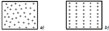
[image:1.595.314.537.431.494.2]The MRE properties are influenced by the percentage of the ferromagnetic particle, on the particles dimension and on the material-microstructure formed during the curing of the elastomeric matrix. To maximize the magnetorheological effect the particle percentage should be equal to about 25-30% and the particle sizes should fall in the range 10–50 μm; furthermore, during curing phase, the particles must be rearranged by applying an external magnetic field that gives the same orientation to the particles and aligns them along the strength lines of the magnetic field (Fig. 1) forming chain-like structures that become locked in place upon the final cure; in this way the material microstructure changes from isotropic to anisotropic. Anisotropic MRE have directional magnetic sensitivity and exhibit a stronger MR effect than the isotropic ones, especially if the magnetic field is applied in the direction of the particle chains [3, 4].
Fig. 1. Schematic particle arrangement in MRE compound: a) isotropic; b) anisotropic
MRE shear modulus Gm depends on the matrix module, G, exhibited by the compound in absence of the magnetic field that, on turn, depends on the matrix module, G0, and on the volume percentage of iron particles, , according to the expression [2]:
G= G0 (1+1.25 +14.1 2) (1) Normally, the particles percentage is comprised in the interval 20-30%; with these values the magneto-rheological effect is maximized while, for greater than 35%, the matrix become too stiff and the stiffness increase, due to the magnetic field, is reduced, as it is shown in [3].
In the following we will refer to a silicon rubber matrix with 25% of ferromagnetic particles; being G0 = 0.15 N/mm2, the compound shear modulus is equal to about: G = 0.33 N/mm2.
The dipolar interaction between particles allows to explain the magnetorheological effect; the model, reported in [2] assumes that the particles are magnetized in the same
Experimental and Numerical Investigation on
MRE Isolators
direction as the external magnetic field and that the particles are small enough to be considered as magnetic dipoles. MRE, in combination with a coil generating the magnetic field and a control system, has already found many applications; it has been mainly proposed for the implementation of vibration reduction systems [5,6,7], noise reduction systems [8], seismic isolators [9], car suspension bushing [10], etc. In [11] it is presented an experimental investigation on an MRE vibration absorber, together with an on-off control algorithm.
In this paper, it is evaluated if MRE material could be conveniently used to implement mounts for equipment or machinery subjected to periodic excitation. In fact, although it is possible to change the material rheological characteristics, to improve the transmissibility, it must be considered that:
to have a satisfactory magnetorheological effect, the compound modulus must be small otherwise, its increase is negligible;
the stiffness increment should be great enough to shift the natural frequency sufficiently far from the initial value;
the compound must not be damaged by the equipment weight and by the shear load due to the relative movement between ground and equipment;
coil and compound should not overheat due to the current circulating in the coil windings.
II. PROBLEM STATEMENT
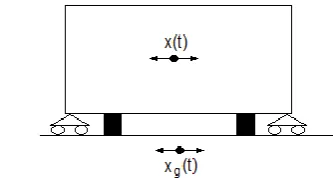
To isolate an equipment from vibrations several mounts can be adopted; to avoid excessive stresses and vertical deformations due to the equipment weight, an extended cross-section area is required. For this reason, the overall vertical stiffness is generally too high in order to achieve the isolation of vertical excitations. To perform a horizontal isolation, it is possible to couple the mounts with a rolling or sliding device that can support the weight of the equipment allowing it to move along any direction of the horizontal plane, with low friction. The vibration mounts can be, therefore, designed considering only the horizontal isolation needs, checking that the maximum relative ground equipment displacement is compatible with the mount deformation and with the required restoring force. The mount can be predominantly shear stressed and therefore, for a first sizing purpose, the shear stress-strain performance can be assumed to be up to 100% strain, although typical vibration isolator dynamic strain is about 50% to minimize fatigue, wear, and heat built up [12]. The adoption of an MRE based mount requires a coil to generate the magnetic field; to prevent the coil and the MRE element from overheating, it is appropriate that the current circulating in the coil windings achieve high intensity values only for short periods of time. Therefore, an MRE based isolators should normally operate as a passive element and should be activated only if the control unit detects specific predefined situation. It is assumed that the mounts are predominantly shear stressed for the presence of a rolling device able to sustain the vertical loads (Fig.2).
With reference to a linear system, the equation of motion of the machine-isolators system is:
(2)
[image:2.595.335.502.133.222.2]being, m is the equipment mass, c and k are the damping and the stiffness of the isolation system respectively, FBTU is the resistance of the rolling device, F(t) is the forcing excitation.
Fig. 2. Isolated equipment
In case of harmonic excitation, characterized by a circular frequency , the isolation linear theory states that a good isolation is achieved if the natural circular frequency, n, of the equipment-isolator system, is sufficiently lower than that of the forcing action, . By choosing the isolation stiffness with reference to the expected frequency excitation , the transmissibility assumes the following expression:
(3)
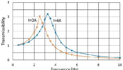
[image:2.595.316.532.569.708.2]Being the damping ratio. Mounts damping and stiffness could assume different values depending on the intensity of the magnetic field that crosses the MRE material. Fig. 3 reports the transmissibility trend obtained for an isolated mass of 1200 kg and two set of stiffness and damping values; the dashed trend presents the maximum transmissibility shifted towards higher values of the frequency; it is obtained from the continuous trend, by increasing stiffness (50%) and damping (25%). These diagrams show that a reduction in transmissibility can be achieved by increasing the mount shear stiffness only if the excitation frequency is lower than the frequency for which the two curves intersect.
Fig. 3. Transmissibility vs frequency for m=1200 kg: a) k1=450 kN/m; =0.9; b) k2= 675 kN/m; =0.9
In the following, after the description of an isolation system constituted by a rolling support and MRE elements, there are reported the experimental results of dynamic tests conducted on a MRE mount. These tests allowed to define the values of the equivalent stiffness and damping of the mounts and to trace the experimental transmissibility curves that provide useful indications for the stiffness control of the insulation system.
III. DESCRIPTION OF THE ISOLATION SYSTEM
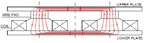
The considered isolation system comprises two MRE mounts, each resting on a coil, connected by two steel plates; if the coils are fed, the magnetic field crosses the mounts and closes the magnetic circuit in the connecting steel plates (Fig. 4).
The isolation system comprises even several ball transfer units (BTU) that are rolling supports, constituted by a main ball rolling on small recirculating balls (Fig.5); these supports, already adopted in other types of isolation systems [12], sustain the equipment weight allowing it to translate in any direction of the horizontal plane with low friction. The BTU rolling resistance depends on the load acting on the main ball that has a beneficial effect up to a value for which each re-circulating ball is sufficiently loaded to roll without sliding; for further load increments, the resistance force increases. Thanks to the BTU presence, the MRE mounts are predominantly subjected to a shear load if the equipment is moved away from its static equilibrium position.
[image:3.595.309.543.53.149.2]Therefore, the isolator restoring force depends on the MRE mount shear stiffness and damping and on the BTU rolling resistance.
Fig. 4. Magnetic circuit in the MRE device
[image:3.595.49.285.438.509.2]The restoring horizontal force, exerted by the mounts, depends on the magnetic field intensity that crosses the MRE material that, in turn, depends on the current intensity circulating in the coil windings. To characterize the mount rheological properties, some cylindrical samples were realized mixing silicone rubber with iron-carbonyl particles into a homogenous mixture. The liquid silicone elastomer was mixed with 25% volume percentage of the carbonyl iron particles, whose dimensions were chosen in the range of 4-6 µm. The samples were formed in cylindrical plastic mold (50 mm in diameter and 9 mm in thickness); to magnify the MRE effect, during the curing phase, permanent magnets were placed, over and under the mold, to orient the particles according to the magnetic field strength lines. The magnetic field intensity generated by the permanent magnets was equal to about 250 mT. The samples were cured for about 24 hours at room temperature.
Fig. 5. Horizontal translation of the isolation system device
If the mounts are not equipped with top and bottom end steel connector plates the mount can be installed with interference to generate a contact pressure at the extremities that prevents slippage.
IV. EXPERIMENTAL SET-UP AND TESTS
The MRE samples were characterized under shear harmonic loads, for different values of the forcing frequency and of the magnetic intensity field, to identify stiffness and damping characteristics, in different operating conditions. Each specimen was constituted by two equal cylindrical elements connected on the opposite sides of a plastic platelet. The specimen, placed on the magnetic core of a coil, was tightened between two steel plates (Fig. 6, 7). The coil has 1500 winding turns made of 1.02 mm diameter wire, AWG17, with an overall length of 310 m, resistance of 6.9 and a maximum dissipated power of 109 W; it gives 6000 Ampere-turns and a magnetic field intensity of 800 mT. The upper side of the coil steel core has a conical
-frustum shape to increment the magnetic intensity field in the specimen [13].
Fig. 6. MRE device under test (DUT).
[image:3.595.309.545.467.557.2]Fig. 7. Photo of the experimental setup
V. TEST RESULTS
[image:4.595.311.543.121.240.2]By means of a gaussmeter (Brockhous mod. BMG101), it was previously measured the magnetic field intensity crossing the specimen, for different values of the current circulating in the coil. By placing the gaussmeter probe between the lower sample and the platelet, the measurement was detected until the intensity current value of 7A (Fig. 8); it was noted that the saturation occurs at about 6 A.
Fig. 8. Magnetic field crossing the specimen vs current intensity
The magnetic field was generated by means of a coil fed with a 4A current, characterized by 1500 turns, made with a 1.02 mm diameter cable (AWG17), having an overall length equal to 310 m (resistance: 6.9 maximum dissipated power: 109 W).
For each dynamic test, characterized by the forcing frequency and by the intensity of the magnetic field, the Force-Displacement cycle was detected. The cycle area is related to the equivalent damping through the relation [14]:
c = A/(X 2 ) (4) being A the cycle area; the forcing circular frequency and X the motion amplitude. The specimen shear stiffness was deduced by the inclination of the major axis of the ellipse that fits the cycle. Figures 9 reports the Force-Displacement cycles, obtained by exciting the specimens with a forcing frequency of 3 Hz and 10 Hz and for two different values of the coil current intensity: 0A and 4A (533 mT).
The obtained experimental results, in terms of equivalent damping and stiffness, are summarizes in Fig. 10; the diagram shows that as the forcing frequency increases, stiffness increases while damping decreases; the magnetic
field increment determines an upward shift of both curves (about 50% in stiffness and 25% in damping).
[image:4.595.310.546.274.443.2]The estimated parameters allow to define the transmissibility diagrams (Fig. 11) considering the actual stiffness and damping values that the material exhibits for different operating condition.
Fig. 9. Force-Displacement cycles at: a) 3 Hz, 0-4 A; b) 10 Hz, 0-4 A
Fig. 10. Experimental comparison between stiffness and damping for non-activated (I=0) and non-activated (I=4A) specimen material vs the excitation frequency.
Fig. 11. Transmissibility evaluated with the rheological characteristics of the MRE specimen
VI. NUMERICAL SIMULATIONS
To study the equipment dynamics, it was considered the one-degree of freedom model expressed by equation (2) in which stiffness and damping vary according the estimated values reported in Fig. 10. The BTU rolling friction force is expressed through a Coulomb model as:
[image:4.595.54.286.350.482.2] [image:4.595.319.533.485.607.2]Fig. 12. BTU friction coefficient vs vertical load.
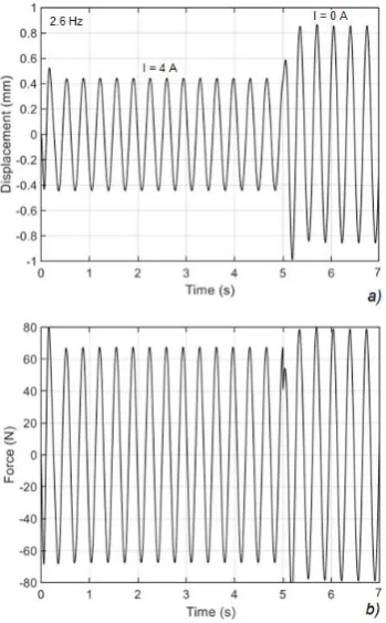
Several numerical simulations were performed exciting the system with a harmonic force at 2.6 Hz, that maximizes the transmissibility for I=0 A. Fig. 13 shows the displacement and the transmitted force for a forcing frequency of 2.6 Hz, in case of activated (I=4A) and deactivated (I=0A) device. It can be noted that deactivating the MRE element both, transmitted force and displacement, increases. In particular, the displacement transmissibility increases of about 100%.
Fig. 13: Displacement (a) and transmitted force (b) for a harmonic excitation at 2.6 Hz and for two differ values of the magnetic field intensity
Other tests were performed exciting the system with an upward sweep-sine, in the frequency range 0-8 Hz and for different sweep rate; examples of system dynamic responses are reported in Fig. 14. The intersection point between the two curves suggests the adoption of an on-off control to reduce the transmissibility; the MRE mount should be activated only if the excitation frequency is lower than about 2.9 Hz. In this way, for example, it should be possible to reduce the transmissibility during the run-up and run-down phases of a machinery as shown in the simulation results reported in Figs. 15 and 16 performed for two different sweep rates.
[image:5.595.310.544.55.213.2]Fig.14. Transmissibility obtained for: I=0 A and I= 4A; on-off control (lower curve with cusp)
Fig. 15. Comparison among the transmitted force obtained for sweep rate of 0.1 Hz/s and I=0 A; I= 4A; on-off control (darker curve with cusp)
Fig. 16. Comparison among the transmitted force obtained for sweep rate of 0.5 Hz/s and I=0 A; I= 4A; on-off control (darker curve with cusp)
VII. CONCLUSIONS
Mounts based on MR Elastomers were prepared and tested to investigate its variations in stiffness and damping if the material is crossed by a magnetic field. The samples were tested for different forcing frequency and different magnetic field intensity. The results, summarized into a single diagram, were adopted to numerically investigate the performances of an MRE based isolator.
The investigation concerned the insulator's response to harmonic and sweep excitations, and the ability to control the material rheological properties to improve the system's dynamic response.
[image:5.595.312.542.250.382.2] [image:5.595.83.258.296.578.2] [image:5.595.313.540.423.578.2]of carbonyl iron particles, if crossed by a magnetic field of 534 mT, showed a stiffness increase of about 50%; the corresponding equivalent damping increment was equal to about 25%; the dynamic response of an isolated equipment was numerically investigated in terms of transmitted displacement/force reduction by adopting a simple on-off control even if the dynamic response would certainly be better if it were possible to increase the material stiffness in a more marked way.
The MRE based device cannot isolate vertical vibration for the presence of the BTU supports that are rigid along the vertical direction. It can be instead adopted for ground vibration excitation due, for example, to the vehicular traffic or seismic motion; in these cases, especially if the vibration source is quite far from the isolated system, the ground motion is predominantly horizontal and therefore this solution can be considered adequate. In these cases, due to the random nature of the excitation, an appropriate control strategy must be used. To limit the energy consumption, the isolator should be designed so that it can normally work as a passive isolator and it should be activated only for short periods of time.
Acknowledgments
The authors are grateful to Giuseppe Iovino and Gennaro Stingo for their collaboration during the setup construction and the execution of laboratory tests.
References
[1] M. Kallio, The elastic and damping properties of magnetorheological elastomers. Thesis for the degree of Doctor of Technology, VTT Technical Research Centre of Finland. ISBN: 9513864472, 2005
[2] Jolly M.R, Carlson J.D, Munoz B.C., A model of the behaviour of magnetorheological materials, Smart Materials and Structures, vol. 5, 1996, pp. 607-614
[3] R. Brancati, G. Di Massa, S. Pagano, Magneto-Rheological properties of elastomeric compound, MDPI Machines (ISSN 2075-1702), n. 7, 2019.
[4] Z. Varga, G. Filipcsei, M. Zrínyi, Magnetic field sensitive functional elastomers with tuneable elastic modulus, Polymer, Vol. 47, n. 1, 2006
[5] Y. Han, W. Hong, L.E. Faidley, Field-stiffening effect of magneto-rheological elastomers, International Journal of Solids and Structures, Vol. 50, Issues 14–15, 2013
[6] Y. Bian ,X. Liang, Z Gao, Vibration reduction for a flexible arm using magnetorheological elastomer vibration absorber, Shock and Vibration, February 2018
[7] Deng H.X., Gong X.L., Wang L.H., Development of an adaptive tuned vibration absorber with magnetorheological elastomer, 15, Smart Materials & Structures, N111-N116, 2006
[8] Xu Z.B., Gong X.L., Liao G.J., et al., An active-damping-compensated magnetorheological elastomer adaptive tuned vibration absorber, Journal of Intelligent Material Systems & Structures, 21, 1039-1047, 2010
[9] Z. Yulin, Z. Xiuyang, Wavelet Adaptive Algorithm and Its Application to MRE Noise Control System, Shock and Vibration, 2015.
[10] Dykedag S. J., Spencer Jrddag B. F., Sain M. K., Carlson J. D. (1998) An experimental study of MR dampers for seismic protection - Smart Materials and Structures n. 7
[11] R. Brancati, G. Di Massa, E. Rocca, C. Rossi, S. Savino, F. Timpone, Elasto-Kinematic Characteristics of Car Suspensions with Magneto-Rheological Bushings, ISBN: 978-3-319-61275-1, Proceedings of the 26th International Conference on Robotics in Alpe-Adria-Danube Region, RAAD 2017
[12] X. B. Nguyen, T. Komatsuzaki, Y. Iwata, H. Asanuma, Fuzzy Semiactive Vibration Control of Structures Using
Magnetorheological Elastomer, Shock and Vibration, ID 3651057, Vol. 2017
[13] Gent A.N. (2012) Engineering with Rubber - How to Design Rubber Components, C.H. Verlag.
[14] R. Brancati, G. Di Massa, S. Pagano, S. Strano, A Seismic Isolation System for Lightweight Structures based on MRE Devices, Proc. of the World Congress on Engineering, WCE 2015, July 1 - 3, 2015.
[15] Graham Kelly S. - Mechanical Vibrations. Theory and Applications - Cengage Learning, 2012.