Abstract—maxillofacial surgery and implants are the scope of rapid development in term of design and preparing. 3D printing technology gives an n opportunity for custom design that satisfy the patient needs. Temporomandibular joints prosthesis is one of the common procedures to retrieve the functionality of the patient mandible. In this work, CT scan images has been used to construct finite element model of mandible. A comparative study of Topology and shape optimization has been used to perform light weight and long life design. Results showed that topology optimization gave better results in term of computational time and fatigue life.
Index Terms— Temporomandibular joint, shape optimization, Topology optimization, parallel processing, Fatigue.
I. INTRODUCTION
andibular fracture is a common for facial injury. Body and angle fractures are more often to be expected. Sportive like cavities, mandibular thickness, and location, promote such fractures to happen. Infection highly frequent with oral cavity related fractures; which makes addressing surgical intervention be exceptionally thorough. Although Medical treatment keep improving, in a similar way to computer integrated circuits (Moore’s Law), Surgical techniques are lagging. Two kind of fixation used as fixed and flexible fixation. , However flexible fixation gives portion of freedom for trading team, fixed fixation in some cases be the best option[1] . Orthodox maxillofacial fractures fixing techniques including wire/plate/screw osteosynthesis and maxillomandibular fixation (MMF) [2]. Michelete et al[3] studied osteosynthesis technique using strip plates (mini-plate) fixed by screws. Plate design based on surgeon view of approach the requirements of maxillofacial region as possible; taking into consecration remodeling of facial safekeeping of functions and correct occlusion. S. Choudhari et al[4] investigated temporary fixation in view of biodegradable close regarded fixation. Plate design stay within orthodox way of thinking however revolutionary material been used. Fracture line stability reviewed by Jones et al[2]. Cases of skewed path of screw, may use for better attachment, and fracture line fixation.
Muazez Al Ali M.Sc. is a lecturer in Al Ayen University / College of Dentistry, Iraq ThiQar (email [email protected] )
Rajaa S. Abass is a lecturer at Al Mamon University College, 14 Ramadan St., Baghdad, Iraq (e-mail: [email protected] ).
Amjad Y. Sahib is a lecturer at University of Wasit, collage of engineering, Wasit Province, Hay Al Rabee, Kut, Iraq (email:
Fracture haematoma stability is vital for healing process. In general, design and chose open reduction materials, is based on surgeon “common sense” and “experience” [5]. Aiding surgeon better judgment with mechanical analysis emerge in finite element analysis[6]. As in structural analysis, stress singularity may appear in bone finite element representation especially with complexity of bone topography. Stress singularity in shade of surgical assessment may not needed to be addressed, such that displacement can be determined with existence of singularity. Due to complexity of bone structure in head and neck in anatomical point of view, facial treatment is often taking a considerably more time to address problem carefully. Facial construction is difficult to construct accurately with taking the surface scan for the face. It is filled with air cavity, soft tissue spots, as arteries, and facial nerves. Individual variation also a fact which should be consider. Computer tomography (CT) and Magnetic resonance imaging (MRI) is effective way to construct 3D modeling of domain to have design within [7]. MRI capable of giving high resolution –high contest image[8], however, it is still considered an expensive diagnostic Tanique. In the other hand CT scan, more cheap and reliable source of data[9]. Also, for some cases in which, patient has metallic implants or tooth filling, MRI is not an option any more. 3D construction from CT imaging Technique allow to get appropriate design for the case in hand and lowering probability of the Malunions and Malocclusion, taking in consideration surgeon adjustment. Another advantage of such modeling technique is to limit Nerve injury[10] within design domain. So, critical locations can be identified and set as conditional design domains. So, fixing parts such as screws and wires will nor contact nerval system or any vital soft tissue areas. The Domain will be selected with both the surgeon and the engineers in order to lower the risk of pre-/post- risks, such as infections elevator spots, soft tissue collateral damage, best available fixing, and enclosure. Desired cavities, appropriate loads, and can be taking into consideration more efficiently [11]. A several cases of optimized plate fixation for fractured mandibles been studied. Designing orthopedic implant as extraskeletal in topographic nature. Loading condition simulate real joint degree of freedom and actual closure pursue in addition to muscular tension forces [12]. Orthopedic implants need precision in preparing. Both bulk and surface [13], characteristics are addressed with noticeably concern. Bio-Tribological characteristics are beyond the scope of this research. Computer-aided design (CAD), gives good database for better precision of workpiece making. Additive manufacturing controlled by computer-aided manufacturing (CAM) protocols[14], gives the ability of control implant mechanical and topological aspects. Different biomaterials were studied with particle
Temporomandibular Joint Orthopedics Design
Using Shape and Topology Optimization
Muazez Al Ali, Rajaa S.Abass, Amjad Y.Sahib
(electrons) or energy wave buckets (laser) rays,[15]. As design done by topology optimizations leads sometimes to rather complicate design, Additive manufacturing seems important choice. Automating custom orthoepic implant with real-time surgical operation is a target, might seems extremely difficult to achieve practically nowadays, but with the advance of CAD-CAM process with TO laying within the core of such processes, it could be achievable target in the scope of near future.
II. SHAPE OPTIMIZATION
Shape optimization is the part of structural
optimization which deals with extremum structural boundaries. The shape is the term of the outline of the structure, mathematically the limit of the function by the first order gradient. In shape optimization, besides the objective function, shape representative is being chosen to address boundaries growth.
Level set method[16],[17] is an example of shape optimization. Mesh morphing on the other hand can be adopted for shape optimization[18]. Phase field is another example of shape optimization [19]. The shape optimization
in terms of the previously mentioned methods is bounded to the discretization design domain. In order to get the best design, the design domain should be rich in size, so the deletion process will not eliminate the better design due to limited spatial period. Some solutions is done to mend this draw back such as different resolution mesh[20], different discretization methodology, one for calculation and one for update, such as FEM and FDM[21] and the extended to use XFEM for extra resolution adaptability[22]. Still the design domain evolution is limited by the fixed discretization methodology. The need of methodologies of extending the discretization beyond the fixed domain are necessity. Mesh morphing is a potential candidate for such task [23]. Morphing in finite element terminology refers to mapping set of nodes of what so-called source elements. The process is widely used in transportation systems [24]and medical simulations[25]. Morphine is performed by setting a traction course for set of nodes on the finite element model, to be moved within the spatial period (in this case upper and lower coordinates). These nodes will be referred to as handlers. Handler are set to move, forcing the design domain to extend or shrink by extruding the elements. Mesh morphing has a drawback such as Mesh quality problem. During the mesh morphing, nodes are moved to the transformed final geometry. It is possible that some elements may get distorted beyond an acceptable limit. This will lead to a negative Jacobean problem within FEM analysis. In order to solve that, mesh size should be chosen to be big enough to not distort badly by the morphing process. Decreasing mesh resolution will affect analysis quality, such as stress. Another solution is to adopt hybrid mesh. In such case, boundary mesh will be added associated with the higher special-order mesh. i.e. 1d mesh at the boundaries associated with 2D mesh for the design domain. This will increase the resolution of the solution, yet it is not quite enough, especially in the case of stress singularity. Another solution is by increasing the degree of freedom of the system with maintaining, same special representation. This is done by adopting higher order element types. In case of needing to increase the mesh resolution, the upper and lower limits of the morphing optimization process should be chosen, in a way to not distorting the element badly (as getting negative Jacobian). In this research level set method has been chosen as the shape optimization methodology due to the speed, accuracy, simplicity, and the robustness comparing to the other methods.
III. TOPOLOGY OPTIMIZATION
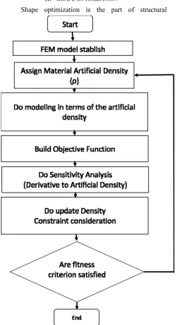
[image:2.595.53.305.176.636.2]Topology optimization has been developed rapidly in last decades, and still a considerable attractive topic to be addressed due to free computer design. It based on the based auto design in order to find the optimal shape of the designed part based on updating the status of subdomain within the design domain, such that the subdomain will take the optimal spatial configuration to construct the final optimal domain. Topology optimization [26] generally divided into layout optimization and generalized shape optimization. The discretization of the domain into finite pates with distinctive relation of the parts based on spatial configuration (as finite difference, boxes, element, and volumes). Topology optimization started as a layout
problem. The fundamentals of layout optimization is doing the design of specific region (design domain), with fixed traction and support in a point belong to that design space [27]. Maxwell in 1869[28] studied in detail the traction effect in frame structure in several papers. Deriving virtual energy formulation to evaluate displacement and applied forces for deterministic and non-deterministic problems, He gave a bound which is the difference of compressive and tensile stress within frame members. Michell[29] used Maxwell lemma, and did exact analysis formulation and optimization. Feasible optimal design can be achieved due to conditioning-based optimization. Hegemier et al[30] review Michell’s structure problem for optimal stiffness, creep resistance and natural frequency. Drucker et al [31] applied constant dissipation per unit volume as their study to stress-strain fields and strain energy. Chan [32] study the optimization of static stability of truss structure by developing a technique to determine topographic based strain filed. Dorn et al introduced numerical discretization in layout optimization. Bartel[33] in his report, minimized structure weight using sequential unconstrained minimization and Constrained Steepest Descent techniques. Charrett and Rozvany [34] adopted Prager – shield implementation in order to find optimal design criterion considering rigid-perfectly plastic systems under multiple loading. Rozvany and Prager [35]studied optimal design of grillage like continua. Their approach was spatial distribution within confined grillage units. Rossow and Taylor[36] used finite element method as a numerical solution to find the optimum thickness of variable thickness sheets. Potential energy for the elastic sheet in-plane stress Assumption was addressed. By introducing holes into plate structure, this work founded shape optimization. Cheng and Olhoff[37] implement finite element method as a numerical solution to optimize the thickness of annual plate with stiffened like approach. Homogenization as averaging method was being adopted in topology optimization a target of the discretized continuous optimality criterion (DCOC) by Bendson et al [38]. This work led to adopt the concept of fictitious material by Bendsoe [39] which then derived the famous Solid Isotropic Material with Penalization method (SIMP). Fig. 1. is showing the algorithm of topology optimization
IV. TEMPOROMANDIBULAR JOINT DESIGN PROCESS
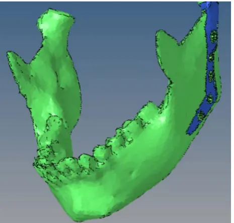
[image:3.595.305.538.49.271.2]The case study is simulated based on CT scan image. The CT scan image then it is converted to a 3d mesh simulation. The design problem that is considered in this work is divided into two regions: the design in which the optimization process will occur; and the non-design domain which is the Mandibular head. Design has been made by using two methodologies, i.e. shape optimization using level set method, and topology optimization.
Fig. 2. Mandible with TMJ prosthesis
Objective function is minimization of stress of the bone with exerting loading condition with the prosthesis. The objective function is as in (1)
min
/
min
. .
, 0
1
d
vms
d d
T T
bone
find
s t
d
V
F u
F u
(1)A fatigue life estimation was performed for the designed prosthesis. The strain-life method was adopted for its accuracy and suitability for the loading conditions. Loading variation was considered as full revisers of 10% of the overall maximum strain, linear variated within the simulated biting time. Modeling of the strain-life is calculated as in (2)[40].
0.095 0.69
0.015381572(2
)
0.35(2
)
a
N
fN
f
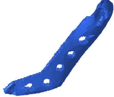
Fig. 2. TMJ prosthesis to be optimized
V. RESULTS
[image:4.595.325.558.53.225.2]The modeling been performed with tetrahedral element shape of finite element model of 300000 element. The computation took parallel processing with GPU based computing of 11 Giga byte of GDRAM. Topology optimization resulted design has been given in comparatively less time comparing to the level set method.
Fig. 3. Topology optimization based TMJ prosthesis
[image:4.595.309.549.272.449.2]Fig. 3. Shape optimization based TMJ prosthesis
Fig. 3. Computational time of topology and shape optimization
Fig. 4. Fatigue life of the designed models using topology and shape optimization
VI. CONCLUSION
Topology optimization showed better results than shape optimization in term of computational time and fatigue life expectancy.
ACKNOWLEDGMENT
The authors would like to thank Dr. Musaddiq Al Ali, for his aid in the subject of fatigue simulation.
REFERENCES
[1] M. Miloro, G. Ghali, P. Larsen, and P. Waite, Peterson's principles of oral and maxillofacial surgery: PMPH-USA, 2004.
[2] J. K. Jones, and J. E. Van Sickels, “Rigid fixation: a review of concepts and treatment of fractures,” Oral surgery, oral medicine, oral pathology, vol. 65, no. 1, pp. 13-18, 1988. [3] F. X. Michelet, J. Deymes, and B. Dessus, “Osteosynthesis with
miniaturized screwed plates in maxillo-facial surgery,” Journal of Cranio-Maxillo-Facial Surgery, vol. 1, pp. 79-84, 1973. [4] S. Choudhari, A. Sulabha, N. Warad, A. Krishna, and S.
Mujawar, “Bio-degradable osteosynthesis system in treatment of mandibular parasymphysis fractures,” J Med Sci, vol. 5, no. 4,
pp. 371-5, 2012.
[image:4.595.54.248.357.521.2] [image:4.595.57.263.561.664.2]Oral and Maxillofacial Surgery, vol. 17, no. 4, pp. 251-268,
December 01, 2013.
[6] H.-S. Kim, J.-Y. Park, N.-E. Kim, Y.-S. Shin, J.-M. Park, and Y.-S. Chun, “Finite element modeling technique for predicting mechanical behaviors on mandible bone during mastication,”
The journal of advanced prosthodontics, vol. 4, no. 4, pp. 218-226, 2012.
[7] W. Parr, U. Chamoli, A. Jones, W. Walsh, and S. Wroe, “Finite element micro-modelling of a human ankle bone reveals the importance of the trabecular network to mechanical performance: new methods for the generation and comparison of 3D models,” Journal of biomechanics, vol. 46, no. 1, pp. 200-205, 2013.
[8] O. Lubovsky, M. Liebergall, Y. Mattan, Y. Weil, and R. Mosheiff, “Early diagnosis of occult hip fractures: MRI versus CT scan,” Injury, vol. 36, no. 6, pp. 788-792, 2005.
[9] P. Magne, “Efficient 3D finite element analysis of dental restorative procedures using micro-CT data,” Dental materials,
vol. 23, no. 5, pp. 539-548, 2007.
[10] E. G. Deliverska, and H. D. Stoyanov, “SURGICAL TREATMENT AND RECONSTRUCTION FOR CENTRAL GIANT CELL GRANULOMA OF MANDIBLE-case report and literature review,” Journal of IMAB-Annual Proceeding Scientific Papers, vol. 19, pp. 407-410, 2013.
[11] A. Sutradhar, J. Park, D. Carrau, T. H. Nguyen, M. J. Miller, and G. H. Paulino, “Designing patient-specific 3D printed craniofacial implants using a novel topology optimization method,” Medical & biological engineering & computing, vol. 54, no. 7, pp. 1123-1135, 2016.
[12] P. Bujtár, G. K. Sándor, A. Bojtos, A. Szűcs, and J. Barabás, “Finite element analysis of the human mandible at 3 different stages of life,” Oral Surgery, Oral Medicine, Oral Pathology, Oral Radiology and Endodontics, vol. 110, no. 3, pp. 301-309, 2010.
[13] A. B. Novaes Jr, S. L. S. d. Souza, R. R. M. d. Barros, K. K. Y. Pereira, G. Iezzi, and A. Piattelli, “Influence of implant surfaces on osseointegration,” Brazilian dental journal, vol. 21, no. 6, pp.
471-481, 2010.
[14] M. A. Ali, "Toward fully autonomous structure design based on topology optimization and image processing." p. 7.
[15] B. H. Lee, J. K. Kim, Y. D. Kim, K. Choi, and K. H. Lee, “In vivo behavior and mechanical stability of surface‐modified titanium implants by plasma spray coating and chemical treatments,” Journal of Biomedical Materials Research Part A,
vol. 69, no. 2, pp. 279-285, 2004.
[16] M. Y. Wang, X. Wang, and D. Guo, “A level set method for structural topology optimization,” Computer methods in applied mechanics and engineering, vol. 192, no. 1-2, pp. 227-246, 2003.
[17] M. A. Ali, “Design Offshore Spherical Tank Support using Shape Optimization,” in Proceedings of the 6th IIAE International Conference on Intelligent Systems and Image Processing 2018, Japan, 2018, pp. 6.
[18] C. Groth, A. Chiappa, and M. Biancolini, “Shape optimization using structural adjoint and RBF mesh morphing,” Procedia Structural Integrity, vol. 8, pp. 379-389, 2018.
[19] P. Penzler, M. Rumpf, and B. Wirth, “A phase-field model for compliance shape optimization in nonlinear elasticity,” ESAIM: Control, Optimisation and Calculus of Variations, vol. 18, no. 1, pp. 229-258, 2012.
[20] T. H. Nguyen, G. H. Paulino, J. Song, and C. H. Le, “Improving multiresolution topology optimization via multiple discretizations,” International Journal for Numerical Methods in Engineering, vol. 92, no. 6, pp. 507-530, 2012.
[21] A. Takezawa, S. Nishiwaki, and M. Kitamura, “Shape and topology optimization based on the phase field method and sensitivity analysis,” Journal of Computational Physics, vol.
229, no. 7, pp. 2697-2718, 2010.
[22] C. H. Villanueva, and K. Maute, “Density and level set-XFEM schemes for topology optimization of 3-D structures,”
Computational Mechanics, vol. 54, no. 1, pp. 133-150, 2014.
[23] A. T. Musaddiq Al Ali, Mitsuru Kitamura, "Comparative Study of Stress Minimization Using Topology Optimization and Morphing Based Shape Optimization."
[24] M. Biancolini, C. Groth, E. Costa, and F. Lagasco, "A mesh morphing based technique to efficiently perform FSI analyses for aeroelastic design applications." pp. 9-12.
[25] I. A. Sigal, M. R. Hardisty, and C. M. Whyne, “Mesh-morphing algorithms for specimen-specific finite element modeling,”
Journal of biomechanics, vol. 41, no. 7, pp. 1381-1389, 2008.
[26] G. Rozvany, “Topology optimization in structural mechanics,”
Structural and Multidisciplinary Optimization, vol. 21, no. 2, pp. 89-89, 2001.
[27] H. L. Cox, The Design of Structures of Least Weight: International Series of Monographs in Aeronautics and Astronautics: Solid and Structural Mechanics: Elsevier, 2014.
[28] J. C. Maxwell, The Scientific Papers of James Clerk Maxwell:
University Press, 1890.
[29] A. G. M. Michell, “LVIII. The limits of economy of material in frame-structures,” The London, Edinburgh, and Dublin Philosophical Magazine and Journal of Science, vol. 8, no. 47, pp. 589-597, 1904.
[30] G. Hegemier, and W. Prager, “On michell trusses,” International Journal of Mechanical Sciences, vol. 11, no. 2, pp. 209-215,
1969.
[31] D. C. Drucker, and R. Shield, Design for Minimum Weight, BROWN UNIV PROVIDENCE RI, 1956.
[32] A. Chan, The design of Michell optimum structures, College of Aeronautics Cranfield, 1960.
[33] D. L. Bartel, Optimum design of spatial structures, IOWA
UNIV IOWA CITY DEPT OF MECHANICS AND HYDRAULICS, 1969.
[34] D. Charrett, and G. Rozvany, “Extensions of the Prager-Shield theory of optimal plastic design,” International Journal of Non-Linear Mechanics, vol. 7, no. 1, pp. 51-64, 1972.
[35] G. Rozvany, and W. Prager, “Optimal design of partially discretized grillages,” Journal of the Mechanics and Physics of Solids, vol. 24, no. 2-3, pp. 125-136, 1976.
[36] M. Rossow, and J. Taylor, “A finite element method for the optimal design of variable thickness sheets,” Aiaa Journal, vol. 11, no. 11, pp. 1566-1569, 1973.
[37] K.-T. Cheng, and N. Olhoff, “An investigation concerning optimal design of solid elastic plates,” International Journal of Solids and Structures, vol. 17, no. 3, pp. 305-323, 1981.
[38] M. P. Bendsøe, and N. Kikuchi, “Generating optimal topologies in structural design using a homogenization method,” Computer methods in applied mechanics and engineering, vol. 71, no. 2,
pp. 197-224, 1988.
[39] M. P. Bendsøe, “Optimal shape design as a material distribution problem,” Structural and multidisciplinary optimization, vol. 1, no. 4, pp. 193-202, 1989.
[40] C. Boller, and T. Seeger, Materials data for cyclic loading: Low-alloy steels: Elsevier, 2013.
[41] B. Yilbas, A. Coban, R. Kahraman, and M. Khaled, “Hydrogen embrittlement of Ti-6Al-4V alloy with surface modification by TiN coating,” International journal of hydrogen energy, vol. 23,
no. 6, pp. 483-489, 1998.