THE ZERO DEFECT COMPANY
XEBEC 51420 GENERAL PURPOSE DISK
CONTROLLER
FOR 5.25" HARD DISK DRIVES AND
5.25" FLOPPY DISK DRIVES
CONTENTS INTRODUCTION
1.1 GENERAL
1.2 DESCRIPTION
1.3 FUNCTIONAL ORGANIZATION
1.3.1 Host Interface 1.3.2 Processor 1.3.3 State Machine 1.3.4 SERDES
1.3.5 Phase Lock Loop 1.3.6 Sector Buffer
SPECIFIC A nONS
2.1 GENERAL 2.2 ELECTRICAL
2.3 PHYSICAL SPECIFICATIONS
2.4 ENVIRONMENTAL REQUIREMENTS 2.5 CONNECTORS
2.6 CONNECTOR PIN ASSIGNMENTS
BOARD SETUP
3.1 GENERAL
3.2 BOARD SETUP
3.3 MOUNTING CONTROLLER
3.4 CONNECTING CABLES 3.5 MULTIPLE CONTROLLERS
3.6 ADDRESS JUMPER GROUP
THEORY OF OPERA nON
4.1 GENERAL
4.1.1 Conventions
4.1.2 Names and Abbreviations 4.1.3 Signal Definitions
4.2 BASIC OPERATING CONFIGURATION
4.2.1 Host Bus Signal Termination 4.3 DETAILED DESCRIPTION
4.3.1 Controller Selection 4.3.2 Command Mode 4.3.3 Data Transfer 4.3.4 Status Bytes
4.4 PROGRAMMING INFORMATION 4.5 COMMANDS
4.5.1 Control Byte
4.5.2 Logical Address (High, Middle, and Low) 4.5.3 Command Set
4.6 SECTOR FORMAT
4.7 EXECUTION OF DIAGNOSTICS 4.8 ERROR CORRECTION PHILOSOPHY
4.9 ALTERNATE TRACK ASSIGNMENT AND HANDLING
4.10 OVERLAPPED SEEKS WITH BUFFERED STEP DRIVES
4.11 SECTOR INTERLEAVING
LIST OF FIGURES
Figure Page Description
1-1
·
...
3 51420 Disk Controller.1-2
·
.
.
.
.
.
.
. .
4 Controller, functional organization. 2-1· . .
.
.
.
. .
.
6 Controller board dimensions.3-1
·
.
.
.
. . .
13 Cable, connector and jumper locations. 3-2·
.
.
.
. . .
. .
16 Operating setups3-3
·
...
18 Normal (fr>r:tory-installed) address jumper. 3-4·
...
18 Changed address jumper (controller 1).4-1
· ...
27 Basic operating configuration. 4-2·
...
29 Controller select timing.LIST OF TABLES
Table 2-1 2-2 2-3 2-4 2-5
·
...
·
...
·
...
Page Description
5 •••••• Controller electrical requirements. 7 •••••• Controller board specifications 7 •••••• Environmental limits.
7 •••••• Controller mating connectors.
8 •••••• Connector 31 and 32 hard disk control signals, pin assignments.
2-6 •••••• 9 •••••• Connector P2 and J3 hard disk data signals, pin assignments.
2-7 •••••• 9 •••••• Connector J5 floppy disk signals, pin assignments.
2-8 • •••• • 10 • ••••• Connector P2 host interface, pin assignments. 2-9 • •••• • 11 • ••••• Connector PI power supply, pin assignments. 4-1 • . . . 20 • ••••• Host bus status signals.
• ••••• Summary of host bus status signals. 4-3 •••••• 23 •••••• Controller-host adapter handshaking. 4-4 •••••• 24 •••••• Host bus control signals.
4-2 · . . . 22
4-5 •••••• 25 •••••• Host bus data signals.
4-6 •••••• 40 •••••• Type 0 error codes, disk drive. 4-7 •••••• 42 •••••• Type 1 error codes, controller.
4-8 •••••• 46 •••••• Type 2 and 3 error codes, command and miscelianeous. 4-9 •••••• 71 •••••• Hard disk sector field description.
4-10 •••••• 72 •••••• FDD Sector/Track Format, MFM. 4-11 •••••• 73 •••••• FDD Sector/Track Format, FM. 4-12 •••••• 80 •••••• Sector interleave example.
[image:4.617.98.475.103.600.2]-iii-1.1 GENERAL
CHAPTER 1 INTRODUCTION
The Xebec S-1420 Disk Controller can control the operation of one or two 5M.-inch Winchester hard disk drives and one or two 5M.-inch floppy disk drives that have the industry standard interface.
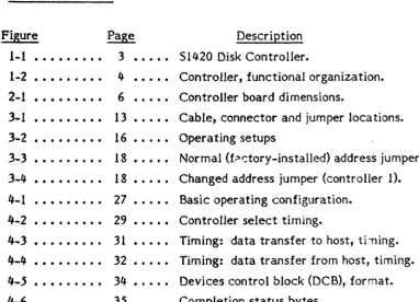
1.2 DESCRIPTION
The S1420 Controller, shown in Figure 1-1, is packaged on a compact printed circuit board whose dimensions are 5-3/4 by 8 inches. The board with this popular form factor mounts easily on many 5M.-inch drives. If not mounted directly on the drive, the Controller takes up very little space in a typical drive enclosure. And because the Controller uses the Shugart Associates System Interface (SASI), it does not require special or complex design considerations in order to communicate with popular host buses. The following list highlights the operating and design features of the Controller.
Interlocked data transfer through the Shugart Associates Systern Interface (SASI).
Microprocessor-based architecture (patent pending). Full-sector buffer.
Hardware 32-bit ECC polynomial with II-bit burst correction for hard disk.
Field-proven data separator.
Hardware 16 bit CRC polynomial for floppy disk. Automatic retries during disk access.
Internal Diagnostics.
Automatic burst error detection and correction.
Separate sector format for ID and data fields with individual check fields for both the ID and data fields.
1.3 FUNCTIONAL ORGANIZA nON
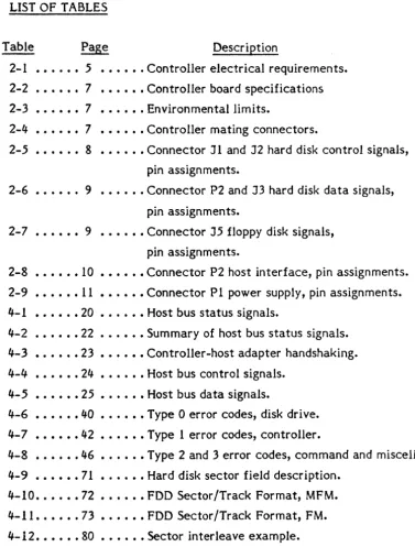
The simplified block diagram in Figure 1-2 shows the functional organization of the Controller. Only the major areas are shown.
1.3.1 Host Interface
The host interface connects the internal data hus to the host adapter; the state machine controls the movement of data and commands through the host interface.
1.3.2 Processor
The eight-bit processor is the intelligence of the Controller; it monitors and controls the operation of the Controller.
1.3.3 State Machine
The state machine controls and synchronizes the operation of the host adapter, SEROES, and sector buffer for the hard disk. 1.3.4 SERDES
The serializer/deserializer (SEROES) converts parallel data from the internal data bus to serial data for transfer to a selected hard disk drive. It converts serial data from the selected disk drive to parallel data which it places on the internal data bus.
1.3.5 Data Separator
The data separator converts serial NRZ data to MFM for transfer to the selected hard disk drive. It converts MFM data coming from the selected drive to parallel data which it places on the internal data bus.
1.3.6 Sector Buffer
The sector buffer stages data transfers between the disk and the host to prevent data overruns.
1.3.7 Floppy Disk Controller
The Floppy Disk Controller (FOC) is an intelligent LSI device capable of executing the lowest level tasks necessary to control a floppy disk drive.
-2-FIGURE 1-2 S1420 CONTROLLER, FUNCTIONAL ORGANIZA nON
[image:8.624.120.479.291.517.2]-4-2.1 GENERAL
CHAPTER 2 SPECIFICA nONS
This chapter contains the overall specifications for the Con troller. These specifications are meant to guide the user in placing the Controller into operation. Some of the specifications indicate limits; the user must adhere to these in order to operate the Controller successfully.
2.2 ELECTRICAL
Table 2-1 lists the electrical requirements of the Controller.
TABLE 2-1 CONTROLLER ELECTRICAL REQUIREMENTS
NOTE: All measurements are made on the Controiier printed circuit board at the power connector Pl.
Voltage Range Current
+5.0 Vdc 4.75 to 5.25 Vdc 2.5 Amp. Max. 2.0 Amp. Typ. +12.0 Vdc 10 • 8 to 13. 2 V de 3.0 rna. Max.
1.0 rna. Typ.
Note: The maximum conducted power supply ripple must not exceed 0.10 volts rms, from 0.1 to 25 mHz.
2.3 PHYSICAL SPECIFICA nONS
(I
ao
'.I"1S
11OIA.
l
•
L--,
-r;J
O.l.OqU
-I
"
--1.9-..,
--
-... ~
I
I
f •
I
I
o.rr
,
I
~ ~
0
'(
"~
.\~Ca"OIA/
I
I
0
I
p
;
I .
-,...
~,
I
i
!,
... ".~-'
-~ -~ II
I
I
!
·1: . .., =
• '7~I
I
I
I
i
G
I
I
I
I
,G
1 I1
I
"
I
0.10
I .'
40. " i.::J
I
llQoiO
1--. - - - -
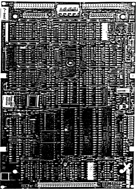
5.15"---FIGURE 2-1 CONTROLLER BOARD DIMENSIONS
[image:10.623.62.578.16.664.2]-6-TABLE 2-2 CONTROLLER BOARD SPECIFIC A nONS
ITEM Width (W) Length (L) Height (H)
(Board thickness, components and lead protrusion)
Weight
MEASUREMENT 5.75 inches 8.00 inches .69 inches
9.0 ounces
2.4 ENVIRONMENTAL REQUIREMENTS
The Controller will operate under the environmental conditions listed in Table 2-3. The Controller does not normally require fans in standard operating environments where airflow is not restricted.
TABLE
2-3
ENVIRONMENTAL LIMITSITEM
Temperature Relative Humidity Altitude
MEASUREMENT
°
to 50 degrees Celsius10 to 95 percent
Sea level to 10,000 feet
2., CONNECTORS
Table 2-4 lists the Controller mating connectors.
TABLE 2-4 CONTROLLER MATING CONNECTORS
DESIG- TYPE/SOURCE
NATION FUNCTION (OR EQUIVALENT)
Jl, J5 Drive control signals AMP 88376-6 J2, J3 Drive data signals AMP 86904-1 J4 Test connector Not applicable
PI Power Supply AMP 1-480424-0 (housing) AMP 350078-4 (pins) P2 Host interface signals AMP 86916-1
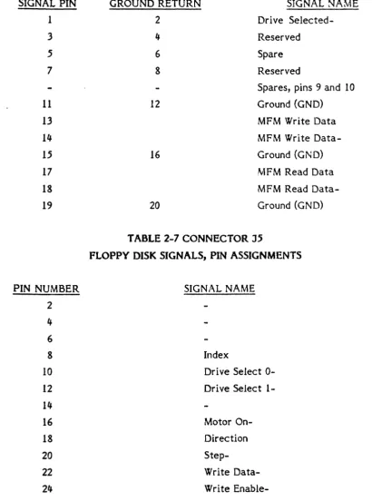
2.6 CONNECTOR PIN ASSIGNMENTS
Tables 2-5 through 2-9 list the pin assignments of the connectors on the Controller board. The tables identify the signals on the pins. The signals in Table 2.6 are defined in Chapter 4, Theory of Operation.
TABLE 2-5 CONNECTOR J 1
HARD DISK CONTROL SIGNALS, PIN ASSIGNMENTS
SIGNAL PIN GROUND RETURN SIGNAL NAME
2 1 Reduced Write
Current-4 3 Head 22_
6 5 Write
Gate-8 7 Seek
Complete-10 9 Track
000-12 11 Write
Fault-14 13 Head Select 20_
16 15 Reserved
18 17 Head Select 21_
20 19
Index-22 21
Ready-24 23
Step-26 25 Dri ve Select
1-28 27 Drive Select
2-30 29 Reserved
32 31 Reserved
34 33 Direction
-8-TABLE 2-6 CONNECTORS J2 AND J3, HARD DISK DATA SIGNALS, PIN ASSIGNMENTS
SIGNAL PIN
1 3 5 7 11 13 14 15 17 18 19
PIN NUMBER
2 4 6 8 10 12 14 16 18 20 22 24 26 28 30
GROUND RETURN
2 4 6 8 12 16 20
SIGNAL NAME
Drive
Selected-Reserved
Spare
Reserved
Spares, pins 9 and 10
Ground (GND)
MFM Write Data
MFM Write
Data-Ground (GND)
MFM Read Data
MFM Read
[image:13.615.83.493.123.674.2]Data-Ground (GND)
TABLE 2-7 CONNECTOR J5
FLOPPY DISK SIGNALS, PIN ASSIGNMENTS
SIGNAL NAME
Index
Dri ve Select 0-Dri ve Select
1-Motor
On-Direction
Step-Write
Data-Write
Enable-Track
00-Write
Data-TABLE 2-8 CONNECTOR P2, HOST INTERFACE PIN ASSIGNMENTS
PIN NUMBER
SIGNAL NAME
2
DATAO-4
DATAl-6
DATA2-8
DATA3-10
DATA4-12
DATA5-14
DATA6-16
DATA7-18
Spare
20
Spare
22
Spare
24
Spare
26
Spare
28
Spare
30
Spare
32
Spare
34
Spare
36
BUSY-38
ACK-40
RST-42
MSG-44
SEL-46
C/D
48
REQ-50
I/O
-10-TABLE 2-9 CONNECTOR PI, POWER SUPPLY, PIN ASSIGNMENTS
PIN NUMBER VOLTAGE
1 +12 Vdc
2 Ground return
:3 Ground return
3.1 GENERAL
CHAPTER 3
BOARD SETUP
This chapter contains the information for setting up and installing the Controller before placing it in operation. These preparatory steps require mounting the Controller in its operating environment, and properly connecting the cables. In addition, the user has the option of using more than one controller with the host adapter in his system. Instructions for connecting multiple controllers appear later in the chapter.
3.2 BOARD SETUP
There are no user configurable hardware options on the 51420 Controller except board address selection. Addres~ selection is discussed in Section 3.6.
3.3 MOUNTING CONTROLLER
The Controller board has four mounting holes. It can be mounted anywhere within the drive enclosure so long as it receives airflow.
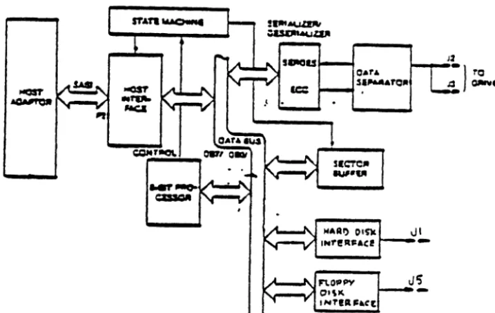
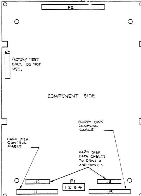
3.4 CONNECTING CABLES
Before the Controller can be placed in operation, the cables to the drive and host must be connected. These cables are listed below:
Jl Control Cable (controller to last drive): maximum 20 feet J2 Data Cable: maximum 20 feet
J3 Data Cable: maximum 20 feet (optional second drive) J5 Floppy Disk Control Cable: maximum 20 feet
PI Power Cable
P2 Host Interface Cable: maximum 15 feet
-12-If using only one drive, Data Cable connector J2 or J3 may be used (i.e., sing! drive does not have to be connected to J2 only).
Note: Do not attempt to connect a cable to connector Jlj.. Connector Jlj. Is for factory test only.
o
o
F
AcrCr;.y i5T ONL'f. 00 Ncr\J~::.
HARe
OlS"'-C.ONi~OI..
<:'~~L.e
.J
IC.OMPONE.NT S\DE
FLO!)P'(' 0\$\<
C.CNi"~O'
[image:18.627.92.549.10.643.2]c'A6\-E
FIGURE 3-1 CABLE, CONNECTOR, AND JUMPER LOCATIONS
Page
-14-o
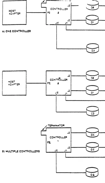
3.' MULTIPLE CONTROLLERS
HOST C::N;MO~:':A
~---~~ ;
," <-.. _ _ _ --I--~
J~
J'--
r
Al ON: COtr.rlOu...~
~CSi .l;:':'~i::4
~i----"';
/r
~IIAINA.T.OR';21---~~-""""
~ t - - - I ~-...,
[image:20.626.118.482.11.644.2]JS J1
FIGURE 3-2 OPERATING SETUPS
-16-3.6 ADDRESS JUMPER GROUP
The Controller supports one of eight unique device addresses. When more than one controller is used in a system, the address jumper on the Controller must be changed. Figure 3-3 shows the address jumper group located next to position 7B; it also shows that terminal (pad) 0 is connected to terminal S. This is the factory-installed jumper, and it sets the Controller's address to
o.
'.CTOAYINSTA~!O
TAAc:a CONNeCTOR (NCAMALI
[image:22.617.111.563.20.632.2]~
_ _ _ 70
FIGURE 3-3 NORMAL (FACTORY -INSTALLED) ADDRESS JUMPER
______ 70
FIGURE 3-If CHANGED ADDRESS JUMPER (CONTROLLER 1)
Page
4.1 GENERAL
CHAPTER 4
THEORY OF OPERA nON
This chapter discusses the theory of operation of the S1420 Controller and lays down the guidelines that will enable the user to use the Controller successfully in any number of applications.
4.1.1 Conventions
Signals or lines can be active in either a high or low state. The terms signal, signal lines, and lines mean the same thing.
A low state is equivalent to a voltage level of 0.8 volts or less, and a high state is equivalent to a voltage level of 2.4 volts or more. Some texts use the term asserted to mean active. In this manual, only the term active is used; if the term asserted appears, it is only for reference.
4.1.2 Names and Abbreviations
A dash (-), or the lack Of one, indicates the active state of a
signal. The active state of a signal is that state which is required for a given operation. When a dash is appended to end of a signal name, the signal is active when it is low. When no dash appears at the end of a signal name, the signal is
active when it is high. Some signal lines have two so-called active (or significant) states. When the level on the line is high, a particular operation takes place. When the level on the line is low, a different operation takes place. The following examples show the use of these conventions.
BUSY - The signal BUSY-is active when it is at a low level because it has the dash appended.
C/D The line C/D (command/data) has a dual purpose; the standard dash (f) indicates duality. It is not apparent what the active states are. The user must look up the definition in the appropriate table.
Other designations used to define signal lines are listed below.
Drv Rcvr OC Tri-State
220/330
Driver Receiver Open collector
Line has three states: impedance
high, low, high
Line termination (on the controller): 220 Ohms to source voltage/330 Ohms to ground.
4.1.3 Signal Definitions
NAME
I/O
The following tables list and define the signals that appear on the lines between the host adapter and the Controller.
TABLE 4-1 HOST BUS STATUS SIGNALS
DRV/RCVR Drv OC
Page
-20-DEFINITION
C/D DrvOC
BUSY-
Drv OCMSG-
Drv OCCommand/Data: This signal line indicates whe ther the if~~orma tion on the data bus consists of command or data bytes. A low means command bytes; a high means data bytes. This signal is qualified by signal REQ-.
Busy: The Controller generates this active low signal in response to the SEL- signal and the addr~ss
bit (D30- to OB7-) from the host adapter. The busy signal informs the host adapter the Controller is ready to conduct transactions on the host bus.
TABLE 4-2 SUMMARY OF HOST BUS STATUS SIGNALS
!/.Q
C/D MSG- DEFINITIONHigh Low High The Controller receives command from the host adapter.
High High High The Controller receives data from another source on the SASI bus.
Low High High The Controller sends data over the SASI bus.
Low Low High The Controller sends error status byte to the host adapter.
Low Low Low The Controller informs the host adapter that it has completed the current command.
-22-TABLE 4-3 CONTROLLER-HOST ADAPTER HANDSHAKING
NAME
REQ-
ACK-DRV/RCVR
Drv OC
Rcvr, 220/330
DEFINITION
Request: The Controller sends
this active low signal to the host adapter to initiate the
controller-host handshaking
sequence. This signal qualifies
signals I/O, C/D and· MSG-.
Acknowledge: The host adapter
generates this active low signal in
response to the REQ- signal from the Controller when the host is
ready to receive or transmit data.
In order to complete the
handshake, the host adapter must
send an acknowledge (ACK-) in
response to each request (~~EQ-)
NAME
RST-
SEL-TABLE IJ.-IJ. HOST BUS CONTROL SIGNALS
DRV/RCVR Rcvr, 220/330
Rcvr, 220/330
Page
-24-DEFINITION
Reset: The host adapter sends this active low signal to the Controller to force the Controller to the idle state. After RST - has become active, any Controller status is cleared. RST - also causes the deactivation of all signals to the drives. The time requirements for the RST - signal are as follows:
Minimum 100 nsec.
Maximum None
TABLE 4-5 HOST BUS DATA SIGNALS
NAME DRV/RCVR
OB7- to DBO- Tri-State, 220/330
DEFINITION
These are the eight data bits (lines) of the host bus (DBO-=LSB).
Each line is also used as address bits to select a controller in systems using multiple controllers (see Chapter 3). The nor mal connection (hardwired on the board) is to DBO- which is the address of controller
o.
Any other connection requires cutting the existing trace on the board and adding a jumper.The following list shows the bit assignments.
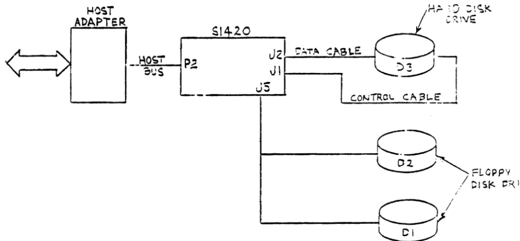
'.2 BASIC OPERATING CONFIGURATION
The basic operating configuration consists of a host adapter, S1420 Controller, and a 5~-inch Hard Winchester Disk Drive. Figure 4-1 shows the basic setup. Also shown is an additional, optional hard disk drive and two
5~-inch Floppy Disk Drives.
The host can be one of a number of computer systems; the host adapter is an interface between the host's bus and the controller.
'.2.1 Host Bus Signal Termination
Host bus control signals DRIVEN by the host adaptor to the Controller (ACK-, RST - and SEL-) do not require termination on the host end. Components used to drive these signals must be able to sink a minimum of 24mA.
Host bus control signals RECEIVED by the host adaptor from the Controller (I/O, C/O, BUSY -, MSG-, and REQ-) must be terminated by the host adaptor with 220/330 (220 Ohms to source voltage/330 Ohms to ground). Components used to receive these signals should be 7414's (or equivalent hysteresis gates).
The Data Bus signals (DB7 - to DBO-) must also be terminated on the host adaptor side with 220/330. Components used to drive the Data Bus must be capable of sinking a minimum of 48mA and those used to receive must be hysteresis gates.
-26-1040ST ADAPTER
PZ
SI 20
Jzl
::!'T.~
c
Jll----~
[image:31.615.58.591.223.470.2]JS
•• 3 DETAILED DESCRIPTION
The following paragraphs describe the interaction between the controller and the host adapter •
•• 3.1 Controller Selection
Before the host adapter can begin a transaction, it must select the controller. The host adapter selects the controller by activating the SEL- control signal and the address bit of the controller. Any bit, OBO- through OB7-, can be the address bit in a system with multiple controllers (all controllers leave the factory with OBO- connected to the controller's address logic). For this discussion, the controller's address is
o.
The timing diagram in Figure 4-2 shows the basic timing requirements. Upon receiving both the SEL- signal and DBO-, the controller activates the BUSY-signal. As shown in the timing diagram, both SF1,- and OBO- must be active (low) before the controller can activate the BUSY-signal. During the selection process, the host has control of the data bus as signified by the deactivation of the I/O line. Selection is complete when BUSY-becomes active. The data bus must be stable 100 nsecs before SEL is activated and remain stable for 100nsec after SEL is deactivated. Note that the Data Bus must be stable before the Select signal is asserted to prevent false selects in a multi-controller environment.
-28-,..1"0
~~S'.I
1040 '" S4'-iI '"
I'"I
M 1"-1I
""I~I
Ob
t;i -
)\
!
i
~
I
I
I
I
~1.-
I
I
I
..
I
I
I
Sou~1-
I
I
I
~
-l~l--~
[image:33.638.50.570.201.577.2]'3 TVP
'.3.2 Command Mode
The Controller receives commands from the host adapter using a handshaking sequence. The Controller places a low level on the C/O (command/data) line to indicate that it wants a command from the host adapter and places a high level on the I/O line to indicate that the movement of information is from the host adapter to the controller. The MSG- line is high.
The Controller activates the REQ- line within 10 microseconds after signals I/O, C/O and MSG- have been placed at high, low and high levels, respectively. The host adapter responds by activating the ACK- signal when a command byte is ready for the Controller. The command byte placed on the data bus by the host must be stable within 50 nanoseconds after the ACK- signal is activated. The command byte must be held stable until REQ- is deactivated. The host deactivates ACK- after REQ- goes high. This completes the handshake for the first command byte. Each succeeding command byte from the host adapter requires the same complete handshake sequence. See Figure 4-4 for data bus, REQ, and ACK- timing. See Table 4-2 for I/O, C/O and MSG- definition.
'.3.3 Data Transfer
The timing diagrams in Figures 4-3 and 4-4 illustrate the ·required timing for data transfer. See Table 4-2 for I/O, C/D
and MSG- definition.
4.3.' Status Bytes
Two bytes of status are passed to the host at the end of all commands. The first byte informs the host if any errors occurred during the execution of the command. The second is a zero byte. It signals to the host that the command is complete. Figure 4-3 shows the data bus, REQ- and ACK-timing. See Table 4-2 for I/O, C/D and MSG- definition. Figure 4-5a shows the format of these two bytes.
-30-On the
~rans!erof
aa~afrom the
con~roller ~oehe
hos~, ~~e C3~~is
s~abl.on :he bus a minimum of
123nsec before
R~~- Q~CC~~~ac~ive.
There is no time lim!c !=om
~!Q- ac~ive ~o AC~- ~~~iV9.After ·the eontroller receives
AC~-, ~!Q- wi~: be~o~e i~~c~:v~wi~hi~
25:0 73 nsec.
If che concroller
~as ~ore ca~a ~o 3~n~,~t
will
set R£Q- active within l.2 co 1.7
~ic=o3e~ !ro~ ~!Qsoi~9
inactive,
if
AC~-was
s.~ inac~ive wi~r.in:.2
~~c=cs.~0:
~4Q- ~oin~ inac~ive. ~heconcroller can
~QCsec
~!~- acci~e.-AC~/-
is
ac~iv..-.
~h. co.n~rol:er:5 reacy
~o ~~-: ~!C- -3C~':'\I$o,bu~ AC~-
is active, the
con~roll.r wa~C5!Qr
AC~-CQ SQ
!~ac~:v~1~h.n
sets
~ZQ- ac~iv.becween
25 and
30nsec
la~er. 7~9r9':'$ ~ctime limit for the controller waicing for
AC~-co
SO
~~ac~!~~.s.
=
-__________
~----
__
----x~---~--a-a-~---)K~---
--J
i_lo4&~I!ollC---,OQ
-SII:a" ----~)~.
- - i.4
1u:.::--1!'-1 ___________________
i ~k-L--I
~
~..,a.
- •.
-j
~
If'~·-A<.lC-
1r... ...
,.
j.1,..-. - .---~~---~~~~
~
[image:35.623.52.594.345.615.2]~---i:~~~M~.W
..
~-~---~~~
I.~ ... _~I
~~ch ~a~a oyte t=ansfe=~9ci from hos~ eo en9 cor.t=oll~r s~a=~3
with t~e ~~Q- goin~ actiV9. :o~ ~~O-eo go active, t~~ hos~ ~~3:
ensure that ACK- is inactive ae ehe beginning
0:
each ~y~~ transfer sequence. A!ter R~Q- goes active, the host sets AC~~ctive while placin~ a byte of data on the bus. ~he~e is no ~i~~
limit from the time R~Q- goes active to AC~-going active. Sowever, there is a time limit of 230 nsec max. for the hos~ t~
?l~c. the data byte on the bus referenced from the AC~- eege. When ACK- goes active, the controller sees R~Q- inac~iv9 wit~ir
1000 nsec max. The host must noe change da~a on the QUS ~nti:
R~Q- soes inactive. 7here is no hold time for t~e data ~n9n
R~Q-90.5
inactive. The=e is no time li~it for the host to set AC~~nactive. Th. controller will not set R~Q- active agai~, !O~ ~~e
next byte to transfer unt~l ACK- goes inactive. -. AC~- coe~ inactive,' in response to RZQ- goi~q ~naCtlVe, t~e cont~o::~= ~:~: set ~~Q- ac~ive within 30C nsec. r~aciy to receive the nex~ ~y~~.
: ! the controller is ready to set ~~Q- active, ~ut ~~~- ~s active, the controller waits for ACK- to ga ina~eiv91 then S9t~
~ZQ- Qetween 23 and 30 nsec later.
i-/O
I
c.-/o
14)~1~
-1 [
II
==
----~---~l ~~I
I
I
I
J
--.J
:I"_C'4_1
- , . . oca-"I~
Ac~-
__________
~________________
~~ am.. ~,-___________
A1't.l_=
I"-~--IO/fS.c.
-, I...!~oo ~e.
,.. ..~
i
[image:36.624.59.589.350.638.2]- , . ~ 1000 ~ ,."....~r~ .. ~'--.4
FIGURE If-If DATA TRANSFER FROM HOST, TIMING
-32-IJ..IJ. PROGRAMMING INFORMA nON
The following paragraphs discuss communications between the Controller and host from the point of view of the codes that are passed. The host sends commands to the Controller through the host adapter. The Controller then performs the commands and reports back to the Iiost.
' • .5 COMMANDS
The host sends a six-byte block to the Controller to specify the operation. This block is the Device Control Block (DC B). Figure 4--5 shows the composition of the DCB. The list that follows Figure 4--5 defines the bytes that make up the DCB.
Bit 7 6 5 4- 3 2 1
o
Byte 0 Command Class Opcode Byte 1 LUN High Address Byte 2 Middle Address
Byte 3 Low Address
[image:37.621.137.411.333.483.2]Figure 4-.5 Device Control Block (DeB), Format
Byte 0 Bits 7, 6 and 5 identify the class of the command. Bits 4 through 0 contain the opcode of the command.
Byte 1 Bits 6 and 5 identify the logical unit number (LUN). Bits 4
through 0 contain logical address 2. If bit 6 is set to zero bit 5 specifies one of the two hard disks. If bit 6 is set to onet bi t 5
specifies one of the two floppy disks.
Byte 2 Bits 7 through 0 contain logical address 1.
Byte 3 Bits 7 through 0 contain logical address 0 (LSB).
Byte 4 Bits 7 through 0 specify the interleave or sector count.
Byte 5 Bi ts 7 through 0 contain the control field.
-34-Bit 7
o
Next to Last Status Byte
6 5 4 3 2 1 0
d d 0 0 0 ERR 0
Bi ts Set to zero. 0,2-4,7
Bit I When set, an error occurred during the last command execution.
Bit 6-5 Logical unit number of drive, d=O to 3.
Bit
Bits
0-7
4.'.1
Last Status Byte
7 6 5 4 3 2 1 0
0 0 0 0
a
a
0 0 [image:39.620.135.521.75.242.2]Set to zero.
Figure 4-6 Completion Status Bytes
The Control Byte
The control field, byte 5, of the DCB allows the user to select options for different commands. The following list defines the bits of the control byte.
Bit 0-5
Bit 6
Spare. Set .. ; zero for future use.
Bit 7 Disable the four retries by the Controller on all disk-access commands. Set this bit only during the evaluation of the performance of a disk drive.
4 • .5.2 Logical Address (High, Middle and Low)
The logical address of the hard disk drive is computed by using the following equation.
Logical Address
=
«CYADR-I) * HDCYL + HDADR) * SETRK+ SEADR
Where: CY ADR
=
Cylinder Address HD ADR=
Head Address SEADR = Sector AddressHDCYL
=
Number of Heads per Cylinder SETRK = Number of Sectors per TrackCylinder zero of the disk drive is reserved by the Controller for diagnostic use and to store the disk drive configuration data. Logical address zero maps physically to cylinder 1, Head 0, sector O. Because of this address shift, the drive appears to be one cylinder smaller than the actual drive capacity. If the host software computes the physical disk address from the logical, remember to add one to the cylinder address to compensate for the address shift. Note that this
address translation is completely hidden from the host software. The host software does not have to compensate for this shift between logical and physical addresses, except for user reporting purposes.
-36-The logical address of the floppy disk drive is computed by using the following equation:
Logical Address = (CYLADR
*
HOCYL + HDADR)*
SETRK + SEA DRThe definitions are the same as above.
4.'.3 Command Set
Bit
Byte 0 Byte 1 Byte 2 Byte 3 Byte 4 Byte 5
The commands fall into eight classes, 0 through· 7; only classes 0, 6, and 7 are used. Class 0 command are data, non-data transfer, and status commands. Classes I through 5 are reserved; Class 6 are disk-to-disk copy commands; and, Class 7
are diagnostic commands.
Each command is described below. The description includes its class, opcode, and format. When a slash (J) represents a bi t
position, the slash means that the value of that bit is not important (a don't-care bit).
4.5.3.1 Test Drive Ready (Class 0, Opcode CO)
This command selects a particular drive and verifies that the drive is ready. The following diagram shows the format of the device control block for this command.
d = drive, 0 to :3
7 6 5 4 :3 2 I 0
0 0 0 0 0 0 0 0
0 d d
I
I
I
I
I
Bit
Byte 0
Byte I
Byte 2
Byte 3
Byte 4 Byte 5
4.5.3.3
4.5.3.4
Note that the 5)4" floppy drive will always show ready since the drive does not return a ready signal.
4.5.3.2
Recalibrate (Class 0, Opcode 01)This command positions the read/write (R/W) arm to track 00.
d
=
drive, 0 to 3r
=
retries7 6 5 4 3 2 1 0
0 0 0 0 0 0 0 1
0 d d
/
/
/
/
/
/
/
/
/
/
/
/
/
/
/
/
/
/
/
/
/
/
/
/
/
/
/
/
/
r 0 0 0 0 0 0 0
Reserved (Class 0, Opcode 02)
This opcode is not used.
Request Sense Status (Clws 0, Opcode 03)
The host must send this command immediately after it detects an error. The command causes the Controller to return four bytes of drive and ControHer status; the formats of these four bytes are shown after the DCB. When an error occurs on a multiple sector data transfer, (read or write), the Request Sense Status command returns the logical address of the failing sector in bytes 1, 2 and 3. If the Request Sense Status command is issued after any of the Format commands or the Check Track Format command, then the logical address returned by the controller points to one sector beyond the last track formatted or checked if there was no error. If there was an error, then the logical address returned points to the track in error. The tables that foHow the formats list the error codes.
-38-Bit
Byte 0
Byte 1 Byte 2
Byte 3 Byte 4 Byte 5
Bit
Byte 0
Bit
Byte 1
Byte 2 Byte 3
d
=
drive, 0 to 37 6 5 4 3 2 1 0
0
a
a
a
a
0 1 Ia
d d/
/
/
/
/
/
/
/
/
/
/
/
/
/
/
/
/
/
/
/
/
/
/
/
/
/
/
/
/
/
/
/
/
/
/ //
Sense Bytes
7 6 5 4 3 2 1 0
SEE BELOW
Bits 0-3 Error Code Bits 4-5 Error Type
Bit 6 Spare, set to zero Bit 7 Address valid, when set
The address valid bit in the error code byte (bit 7) is relevant only when the previous command required a logical block address; in which case it is always returned as a one otherwise it is set to zero. For instance, if a Recalibrate command is followed immediately by a Request Sense Status command, the address valid bit would be returned as zero since this command does not require a logical block address to be passed in its DCB.
7
o
6 5 4
d d
Middle Address Low Address
3 2 1
a
Table 4-6 Type 0 Error Codes, Disk Drive
HEX
CODE
00
01
02
03
04
DEFINITION
No Error Occurred. This code is always returned if no error had occurred during the previous command.
No Index Signal from the Drive. This occurs on the hard disk during and data transfer or format command if a normal drive select occurs, the drive is ready, but no index signal is detected from the drive within two revolutions of the disk.
No Seek Complete Signal from the Drive. This error occurs on non-buffered seek processing if the Controller does not receive the Seek Complete Signal from the Drive within one second following the last step pulse.
Write Fault Signal Received from the Drive. This error occurs if the controller detects an active write fault signal from the disk drive either at the completion of a sector data transfer or initially after a successful drive select and the drive indicates ready.
Disk Drive Not Ready. This error occurs if the controller fails to receive the select signal from the drive, or the drive indicates not ready after selection.
-40-06
08
OA
Track 00 Not Found. After stepping the drive 200 more steps than the number of cylinders on the hard disk, or 77 steps on the floppy during a recalibrate command, the Track 00 Signal was not received from the drive.
Disk Drive Still Seeking. This status is returned in response to a test drive ready command if a buffered step seek was issued to a hard disk drive and the drive has not returned the seek complete signal. Software must time the seek to insure no system hang occurs if the drive fails to return the seek complete signal. Treat a seek incomplete condition the same as error code 02.
Controller Not Initialized. This status is returned if the controller is requested to execute a drive command, but the controller has not received an initialize Format Command for this drive, or is
HEX
CODE
10
11
12
Table 4-7 Type 1 Error Codes, Controller
DEFINITION
ID Read Error. During a data transfer or format
command, address marks were detected, but the
target sector was not found and an ECC or C RC
error occurred on one or more ID fields.
Media defects may be overcome by deleting the
defective sectors from system use or assigning an
alternate track.
Uncorrectable Data Error in the Data Field. The
controller detected a data error on the hard disk
that could not be corrected using ECC, or the
controller detected a CRe error on floppy.
Media defects may be overcome by deleting the
defective sectors from system use or assigning an
alternate track.
Sector Address Mark Not Found. The controller
did not detect an address mark (AM) from the drive
within its timing window. An address mark is a
special recording pattern preceding the ID field of
a sector. The AM is only written at format time.
The AM tells the controller where new sector
starts. The error may occur during any data
transfer or format commands. The error may
mean that no address marks were detected on the
track, or the target sector address mark was not
detected.
Media defects may be overcome by deleting the
defective sectors from system use or assigning an
-42-13
14
1.5
16
17
18
19
alternate track.
A Write Protect Error. A Write operation was attempted on a write protected floppy disk.
Target Sector Not Found. The target sector was not located wi thin two revolutions of the disk. This error usually occurs when there is a media de fect in the address mark field of the target sector.
Seek Error. After a seek, the target disk address did not match the address read from the disk. Either the cylinder or head bytes did not match.
Format Track Not Complete. The FDC chip failed to completely format a track on the floppy disk.
FDe Busy. The Floppy Disk Controller (FDC) was busy when it should have been idle, and the controller was unable to clear the condition.
Correctable Data Error. The controller detected a media error on the hard disk while reading that was corrected by ECC. This error code informs the host software that error correction has taken place. This is the only error where the data is passed to the host before returning the error status.
IA
IB
Ie
10
IE
Format Error. During execution of a check track command, the controller detected an unformatted track, the wrong interleave on disk, or an In ECC error on at least one sector.
Foe Lost Data Error. The FOe had either a data overrun or underrun condition during the last command.
Controller Detected a Direct Access to an Alternate Track. A track that has the alternate track flag set in the ID has been directly accessed by the host on the hard disk, instead of coming from the defective track that is assigned to this alternate track. Care must be used in software to insure that tb'" alternate track area is not accessed directly during data transfer commands.
The Designated Alternate Track is already assigned to another Defective Track. Host software has attempted to assign an alternate track to replace a defective track, but the alternate had previously been assigned to a defective track. If an alternate track is no longer needed, the host software must reformat the track using the FORMAT TRACK command before attempting to reassign the track again.
Assigned Alternate Track Not Found. A defective track has been assigned an alternate track, but the alternate track does not have the alternate track bit set in the ID field. This may be caused by reformatting the alternate track with the format track command without reprocessing the defective track.
Table IJ-S Types 2 and 3 Error Codes, Command and Miscellaneous
HEX
CODE 20
21
22
23
30
31
32
DEFINITION
Invalid Command: The controller has received an invalid command from the host.
Illegal Disk Address: The controller detected an address that is beyond the maximum range.
Illegal Parameter: The coatroller detected an option, or combination of options that are illegal for this device.
Copy Completion Mismatch: During Copy operation the last section written to the target drive was partly but not completely filled with data from the source drive.
RAM Error: The controller detected a data error during the RA!v1 sector-buffer diagnostic.
Program Memory Checksum Error: During its internal diagnostic, the controller detected a program-memory checksum error. This is caused by a defect in the program memory chip of the controller.
ECC Polynomial Error: During the controller'S internal diagnostic, the hardware ECC generator failed its test.
-46-The following is a summary of the error codes returned as the result of the Request Sense Status command.
NOTE: The address valid bit (bit 7) mayor may not be set and is not included here for clarity.
Error Code (hex) Meaning.
00 • • • • • • • • • • • • • •• No error detected (command completed ok). 01 ••••••••••••••• No index detected from disk drive.
02 • • • • • • • • • • • • • •• No seek complete from disk drive 03 ••••••••••••••• Write fault from disk drive
04 • • • • • • • • • • • • . •. Drive not ready or not selected.
05 ••••••••••••••. Not used.
06 ••••••••••••••• Track 00 not found.
07 . . . . .. Not used.
08 ••••••••••••••• Disk drive still seeking.
09 . . . . .. Not used.
OA ••••••••••••••• Controller not Initialized. OB-OF • • • • • • • • • • • • •• Not used.
10 ••••••.•••••••• ID field read error.
11 • • • • • • • • • • • • • •• Uncorrectable data error. 12 • • . • • • • • • • . • • •• Address mark not found. 13 ••••••••••••••• Write protect error. 14 ••••••••••••••• Target sector not found.
15 . . . Seek error.
16 •••••••••.•••.. Format track not complete. 17 ••••••••••••••• FDC busy error.
18 ••••••.•••••••• Correctable data error. 19 ••••••••••••••• Bad track flag detected. lA ••••••••••••••• Format error.
1 B ••••••••••••••• Not used.
1 C ••••••••••••••• Direct access to an alternate track. 1 D ••••••••••••••• Alternate .:Jready assigned.
IE •••••.••••••••• Alternate)t found.
1 F ••••••••••••••• Alternate .::5signed to defective track. 20 ••••••••••••••• Invalid command.
21 • • • • • • • • • • • • • •• Illegal disk address.
22 • • • • • • • • • • • • • •• Illegal parameter.
23 ••••••••••••.•• Copy completion mismatch.
24-2F • • • • • • • • • • • • •• Not used.
30 ••••••••••••••• Ram diagnostic failure.
31 • • • • • • • • • • • • • •• Program memory checksum error.
32 • • • • • • • • • • • • • •• ECC diagnostic failure.
4.5.3.5 Format Drive (Class 0, Opcode 04)
This command formats all sectors with ID and data fields according to the selected interleave factor. Formatting begins with the first sector of the track specified by the starting address of the DCB. The controller will format all tracks from the starting track to the end of the disk. If the b bit is zero, the data fields will contain a 6C for the hard disk. The data field is formatted with an E5 for the floppy FM format, and a 40 for the floppy MFM format. It the b bit is one, the data already contained in the buffer is used to format the hard disk. The b bit is ignored for the floppy format. If the T bit in the initialize format command is set to one, the hard disk format will leave a 300 microsecond gap before index. This format is to be used for imbedded servo field drives. If the T bit is reset, the entire track is used for formatting the hard disk. This bit is ignored for the floppy format. The format command does not read verify the sector.
Following the format of the hard disk, the drive parameters passed in the Initialize Format Command are written and verified on the maintenance cylinder (cylinder 0) of the hard disk. Both the hard disk and floppy disk parameters are stored.
-48-d = drive, 0 to 3 r = retries
b = if set, use buffer contents
Bit 7 6 5 4 3 2 1 0
Byte 0 0 0 0 0 0 1 0 0
Byte 1 0 d d High Address Byte 2 Middle Address
Byte 3 Low Address
Byte 4 0 0 0 Interleave
Byte 5 r 0 b 0 0 0 0 0
".5.3.6
Bit
Byte 0 Byte 1 Byte 2 Byte 3 Byte 4 Byte 5
Check Track Format (Class 0, Opcode 0.5)
This command checks the format on the specified track for correct ID and interleave on the hard disk only.
does not read the data field.
d
=
drive, 0 or 1 r=
retries7 6 5 4 3 2 1
0 0 0 0 0 1 0
0 0 d High Address Middle Address
Low Address
0 0 0 Interleave
r 0 0 0 0 0 0
Interleave: 1 to 31 for 256 byte sectors. 1 to 16 for 512 byte sectors. 0
1
0
The command
If • .5.3.7 Format Tracks (Class 0, Opcode 06)
This command formats the number of tracks specified in the two data bytes passed following the DCB. The format operation starts the first sector of the track specified by the disk address bytes in the DCB. The controller recalibrates the drive, seeks to the starting track, and begins the format operation. Formatting continues on a track by track basis until the track count is exhausted or the end of the disk is reached. If the track count exceeds the disk capacity, the controller returns an illegal address error after formatting the last track on the drive. The data field is filled with the default data pattern 6C Hex on the hard disk. If bit 5 of byte 5 is set to one, the dat,- field will be taken as is from the buffer for the hard disk. The data fields on the floppy are formatted with E5 for FM and 40 for MFM data. If the T bit in the initialize format command is set to one, the hard disk
-50-Bit
Byte 0
Byte 1
Byte 2
Byte 3
Byte 4
Byte 5
format will leave a 300 microsecond gap before index to allow
for the imbedded servo area if the disk requires it. If the T bit is zero, the entire track is used.
If the two track count data bytes contain zero, the initialization data will be written on the reserved cylinder
(Cylinder 0). No tracks ..1re formatted. This allows changing
the initialization parameters for the drive without
reformatting the drive. Issue the Initialize Format Command,
followed by the Format Tracks Command with the track count
set to zero to permanently update the disk drive parameters.
d
=
drive, 0 or 3 r = retriesb
=
use data already in the buffer s=
imbedded servo hard disk7 6 5 4 3 2
0 0 0 0 1 0
1
0
0 0 d High Address
Middle Address
Low Address
Block Count
r 0 b S 0 0 0
The two byte track count is transferred
significant byte first.
0
0
0
4.5.3.8 Format Bad Track Class (Class 0, Opcode 07)
Bit
Byte 0
Byte 1
Byte 2 Byte 3 Byte 4 Byte 5
This command formats the specified track and sets the bad-sector flag in the ID fields on the hard disk. It does not write the data fields. If the track is accessed with normal data transfer commands, an access to defect~ye track (Error Code 19 Hex) is returned.
d = drive, 0 or 1 r = retries
7 6 5 4 3 2 1 0
0 0 0 0 0 1 1 1
0 0 d High Address Middle Address
Low Address
0 0 0 Interleave
r 0 0 0 0 0 0 0
Interleave:
1 to 31 for 256 sectors 1 to 16 for 512 sectors
-52-•. 5.3.9 Read (Class 0, Opcode 08)
Bit
Byte 0 Byte 1 Byte 2 Byte 3 Byte 4 Byte 5
This command reads the specified number of sectors, starting with the initial sector address contained in the DCB. Each sector of data is 128, 256 or 512 bytes. The number of bytes per sector is set by the Initialize Format command. If bit 6 of byte 5 is reset, the Controller will reread a defective sector before attempting error correction on the hard disk. If the reread occurs without error, or the error is correctable, the Controller will pass the data to the host and not report an error. If bit 6 of byte 5 is set, the controller attempts error correction without a reread of the defective sector. If the error is correctable, the Controller passes the data to the host, then terminates tl...! operation with a correctable data error. If the error is uncorrectable, in either case, the operation is terminated with an uncorrectable data error and the data is not returned to the host.
d
=
drive, 0 to 3 r=
retriesa
=
retry option on data ECC error7 6 5 4 3 2 1 0
0 0 0 0 1 0 0 0
0 d d High Address Middle Address
Low Address Block Count
~.5.3.10 Read Verify (Class 0, Opcode 09)
Bit
Byte 0 Byte 1 Byte 2 Byte 3 Byte 4 Byte 5
This command executes the same as the read data command, except that no data is passed to the host. This command may be used to verify data integrity without having to transfer the data to the host. If bit 6 of byte 5 of the DCB is reset, the Controller will reread a defective sector before attempting error correction. If no data error occurs on the reread, the verify will continue and no error will be reported. If the error occurs again, error correction is applied, and the correctable or uncorrectable data error returned to the host. If bit 6 of byte 5 is set, error correction is applied without a reread step, and the error is returned to the host.
d
=
drive, 0 or 1 r=
retriesa
=
retry option on data ECC error7 6 5 4 3 2 1
a
0 0 0
a
1 0a
1a
d d High Address Middle AddressLow Address Block Count
4.5.3.11 Write (Class 0, Opcode OA)
Bit
Byte 0 Byte 1 Byte 2 Byte 3 Byte 4 Byte 5
4.5.3.12
Bit
Byte 0 Byte 1 Byte 2 Byte 3 Byte 4 Byte 5
This command writes the specified number of sectors, starting with the initial sector address contained in the DCB. Each sector of data can be 128, 256 or 512 bytes long. The sector size is determined at format time.
d
=
drive, 0 to 3 r=
retries7 6 5 4 3 2 1 0
0 0 0 0 1 0 1
a
0 d d High Address Middle Address
Low Address Block Count
r 0 0 0
a
a
a
0Seek (Class 0, Opcode OS)
This command initiates a seek to the track specified in the DCB. The drive must be formatted.
d
=
drive,a
to 3 r=
retries7 6 5 3 2 1
a
0
a
a
0 1 0 1 I0 d d High Address Middle Address
Low Address
/
/
I
I
I
I
I
I
4.5.3.13
4.5.3.14
Bit
Byte 0
Byte 1
Byte 2 Byte 3 Byte 4 Byte 5
4.5.3.15
Reserved (Class 0, Opcode OC)
Read ECC Burst Error Length (Class 0, Opcode 00)
This command transfers one byte to the host. This byte contains the value of the ECC burst length that the controller detected during the last Read command on the hard disk. This byte is valid only after a correctable ECC data error, type
1,
code 8.7 6 5 4 3 2 1 0
0 0 0 0 I 1 0 1
/
/
/
/
/
/
/
/
/
/
/
/
/
/
/
/
/
/
/
/
/
/
/
I
/
/
/
/
/
/
/
/
/
/
/
/
/
/
/
/
Format Alternate Track (Class 0, Opcode OE)
This command assigns an alternate track to a defective track on the hard disk. After the alternate track is assigned, the Controller will automatically move all normal read/write operations from the defective to the alternate track. This change is transparent to the host during normal read and write operations.
Format Alternate Track will format all sectors of the defective track with a physical disk address of the alternate track. The alternate track is formatted to identify it as an alternate track.
-56-d
=
drive, 0 or 1 r=
retriesb
=
use buffer datas
=
if set for data field hard disk has imbedded servo fieldBit 7 6 5 3 2 1
a
Byte 0 0 0 0 0 I I 1 0
Byte 1 0 0 d High Address Byte 2 Middle Address
Byte 3 Low Address
Byte 4
/
/
/
/
/
/
I
/
Byte 5 r 0 b s 0 0 0 0
The logical address in the command DCB points to the defective track. the address of the alternate track is passed as three data bytes following r,e command block. The address is passed to the Controller MSB first, followed by the MID and LSB in order. Both addresses are used as track addresses, and formatting begins at sector zero of each track.
If bit 5 of Byte 5 is set to ~ one, the controller uses the data already in the buffer as the data bytes instead of the 6C Hex default data pattern.
After receiving the command block and the alternate address data bytes, the Controller does the following to assign the alternate track:
A) Seeks to the "Alternate .\ssigned Track" and verifies that the track is not already assigned:. ~ an alternate or not flagged as a defective track. If either vf the above conditions is true, the operation is aborted and an error code ID hex returned.
B) If the track is unassigned, the Controller formats the track as an assigned alternate track.
C) Seeks to the "Defective Track" and formats the track as a defective track with the alternate track assigned.
Note: All data fields on both tracks are destroyed by the format operation.
Notes on host system use of the Format Alternate command:
A) The alternate tracks are not available for system use. It is the responsibility of the host to reserve the alternate track area on the disk, and to prevent that area from direct access by the users. The number of spare tracks to allocate is normally specified by the drive manufacturer. Generally, this is one spare allocated per 100 tracks on the disk.
B) The Controller must be initialized to access the whole drive, including the alternate track area.
C) To initialize a disk, the following procedure should be followed:
1) Format the entire disk, including the spare track area.
2) Verify the disk with controller retries disabled. Form a list of media defects.
3) For each media defect, assign an alternate track. To be safe, include the list of defective tracks provided by the drive manufacturer.
D) In system operation, the alternate tracks are invisible to the host. The Controller will automatically seek to the assigned alternate track when the host accesses the flagged defective track. IIConsecutivell accesses to a flagged track does not
cause the Controller to seek back to the defective track and return to the alternate track. The Controller will maintain
-58-•• 5.3.16
BIt
Byte 0 Byte 1 Byte 2
Byte 3 Byte 4
Byte 5
position on the alternate track as long as the host accesses the same defective track.
Write Buffer (Class 0, Opcode OF)
This command is used to fill the Controller buffer with a data pattern from the host. This command can be used with the read buffer command to test buffer operation, or to provide a non-standard data pattern to be written into the data fields by the various format commands.
7 6 5 4 3 2 1 0
0 0 0 0 1 1 I 1
I
I
I
I
I
I
I
I
I
I
I
I
I
I
I
I
I
I
I
I
I
I
I
I
I
I
I
I
/
I
I
I
I
I
I
I
/
I
I
I
The command accepts either 256 or 512 bytes. The Controller must be initialized with the drive parameters for hard disk drive 0 before this command is issued so that the Controller knows if the block size is 256 or 512 bytes. If no drive is attached to the Controller, the host must issue the Initialize Format command for hard disk drive 0 prior to issuing this command.
4.5.3.17 Read Buffer (Class 0, Opcode 10)
Bit
Byte 0 Byte 1
Byte 2
Byte 3
Byte 4 Byte 5
7 6 5 4 3 2 1 0
0 0 0 1 0 0 0 0
/
/
/
/
/
/
/
/
/
/
/
/
/
/
/
/
/
/
/
/
/
/
/
/
/
/
/
/
/
/
/
/
/
/
/
/
/
/
/
/
This command accepts either 256 or 512 bytes of data. The Controller must be initialized with hard disk drive parameters for drive 0 before the Read Buffer command is issued so that the Controller knows if the block size is 256 or 512 bytes. If no drive is attached to the Controller, the host must issue the Intialize Format command for drive
a
prior to issuing this command.4 • .5.3.18 Initialize Format (Class 0, Opcode II)
This command allows the user to set up the Controller for various disk drives of different configuration. The host specifies all the necessary parameters to enable the Controller to control the drive. This command must be issued prior to the drive format command. After the hard disk drive is formatted, the Controller will store these parameters on the maintenance cylinder (cylinder 0) of the drive. Both the hard . and floppy disk parameters are stored on hard disk drive. Following subsequent Controller resets, the Controller will fetch initialization data from the maintenance cylinder of the drive. This means that the host software does not issue this command during normal use of the system, but only under a special format utility program.
-60-The Controller does not have any default ini tializa t ion
parameters at reset time. If the Controller cannot read the initialization parameters from the drive, this command must
be issued before any command that accesses the drive.
Failure to adhere to this rule will result in a "Controller not
initialized" error (Error Code OA Hex).
d
=
drive, 0 to 3Bit 7 6 5 4 3 2 1 0
Byte 0 0 0 0 1 0 0 0
Byte 1 0 d d
/
/
/
/
/Byte 2
/
/
I
/
I
I
I
/
Byte J
/
I
I
I
I
/
/
/Byte 4
/
/
/
/
/
I
/
/
Byte 5
I
/
I
I
I
I
/
/
After sending the command (DCB) to the' Controller, the host
must follow with a ten byte data block. This block provides all
the initialization parameters to the Controller. The hard disk
configuration block is:
Bit 7 6 5 4 J 2 1 0
Byte 0 C C C C C C C C
Byte 1 C C C C C C C C
Byte 2 0 0 0 0 0 H H H
Byte J S S S S 0 0 0 T
Byte 4 0 0 0 0 0 0 D D
Byte 5 W W W W W W W W
Byte 6 W W W W W W W W
Byte :-' p P P F P P P P
Byte 8 p P P P P P P P
Where:
C
=
Number of Cylinders (Most Significant byte first) H = Number of HeadsS = Step Option
0000 - 3 msec step
000 1 - 15 usee buffered step 0010 - 30 usee buffered step 0011 - 70 usee buffered step 0100 - 200 ust...: buffered step T
=
Encoded Disk Drive Typea
=
Standard drive1 = Imbedded servo fixed drive D
=
Data Field Size01
=
256 data bytes per sector (32 sectors per track) 10 = 512 data bytes per sector (17 sectors per track) W=
Reduced Write Current CylinderP
=
Write Precompensation CylinderE
=
Maximum burst error correction length, up to 11