1
Manufacturing-error-based maintenance for high-precision machine
1tools
2Authors:
3
Shengyu Shi, PhD 4
1. Shaanxi Key Laboratory of Mechanical Product Quality Assurance and Diagnostics, School of Mechanical 5
Engineering, Xi’an Jiaotong University, Xi’an, 710049, P.R. China 6
2. Manufacturing Metrology Team, Faculty of Engineering, University of Nottingham, Nottingham, NG7 2RD, 7
United Kingdom 8
Email: [email protected] 9
10
Jing Lin, PhD, Professor 11
3. State Key Laboratory for Manufacturing System Engineering, Xi’an Jiaotong University, Xi’an, 710049, 12
P.R. China 13
Email: [email protected] 14
Phone number: 86-29-83395041 15
Fax: 86-29-83395041 16
17
Xiaoqiang Xu, PhD Candidate 18
1. Shaanxi Key Laboratory of Mechanical Product Quality Assurance and Diagnostics, School of Mechanical 19
Engineering, Xi’an Jiaotong University, Xi’an, 710049, P.R. China 20
Email: [email protected] 21
22
Xiaobing Feng, Postdoctoral Research Fellow 23
2. Manufacturing Metrology Team, Faculty of Engineering, University of Nottingham, Nottingham, NG7 2RD, 24
United Kingdom 25
Email: [email protected] 26
27
Samanta Piano, PhD, Assistant Professor 28
2. Manufacturing Metrology Team, Faculty of Engineering, University of Nottingham, Nottingham, NG7 2RD, 29
United Kingdom 30
Email: [email protected] 31
2
Abstract:
1
Nowadays, the condition-based maintenance (CBM), in which repairs are triggered by the heuristic symptoms 2
of the component faults, is finding increasing applications in the industrial fields. However, for the high-3
precision machine tools, the conventional CBM might not be the optimal option, which is uneconomic and 4
incapable of ensuring their machining accuracy. In order to overcome these shortcomings, this paper propose 5
the manufacturing-error-based maintenance (MEBM), where the repairs are initiated based on the 6
manufacturing errors instead of the heuristic symptoms. In MEBM, repairs are taken properly at the occurrence 7
of the excessive machining errors, and therefore, the premature and redundant maintenance can be avoided 8
and the maintenance cost can be minimized; what’s more, the machining errors are controlled in the closed 9
loops, and therefore, the machining accuracy can be guaranteed. Based on the principles of the MEBM, a 10
prototype maintenance system – the transient backlash error (TBE) based maintenance system – is established. 11
To achieve this aim, first, the width of the backlash in the mechanical chain is measured by utilizing the built-12
in encoders and the analytical mapping relationship between the backlash width and the TBE is derived. 13
Relying on these foundations, the TBE can be indirectly estimated. Then, the warning threshold of the TBE is 14
customized according to the permissible roundness error of the workpiece. Thus, the maintenance actions can 15
be precisely implemented: when the monitored TBE exceeds its warning threshold, maintenance workers will 16
be notified to lessen the backlash width, and meanwhile, the permissible maximal size for the backlash will 17
also be informed. 18
19
Keywords: CNC machine tools; Machining error; Maintenance; Mechanical chain accuracy; Lead error; 20
3
1.
Introduction
1
Maintenance has become increasingly important and versatile in industrial field. For critical and fatal 2
systems, such as aircrafts, submarines, and nuclear systems, preventative and predictive maintenance has been 3
widely adopted to reduce the sudden stoppages, thus, to achieve the reliability capabilities of the equipment 4
and to minimize the catastrophic disasters [1]. For equipment manufacturers, condition monitoring systems 5
can provide them with valuable feedback for constant improvement of their equipment [2]. For production 6
systems (e.g. machine tools), proper maintenance contributes positively to product quality enhancement, 7
production increment, and life-cycle cost reduction [3-4]. 8
Historically, breakdowns were considered as random occurrences [5-6]. Only when the equipment ceased 9
to work, was it repaired to prolong its life span. After the 1950s, it was discovered that the failure times are 10
actually distributed in a certain way rather than completely intangibly. Since then, the concept of preventative 11
maintenance (PM) has been advocated, and time-based maintenance (TBM) has been intensively studied 12
relying on the priori knowledge of failure time distribution (FTD) or the degradation model [4, 7-8]. The main 13
ambition of the TBM is to reduce or even eliminate the sudden breakdowns. This is because compared with 14
the scheduled PM, the sudden breakdowns generally require more maintenance cost (time), and in some cases, 15
it might lead to catastrophic disasters. Unfortunately, in industrial fields, it is always quite difficult or even 16
impossible to derive the exact FTD or the degradation model, which has prohibited the feasibility and 17
widespread use of the TBM [2]. 18
Since the 1970s, due to the theoretical development in signal processing and pattern recognition techniques, 19
researchers have achieved remarkable success in the technology of mechanical fault diagnosis [7, 9]. 20
Thereafter, the condition-based maintenance (CBM) was put forward, where the predictive repairs are taken 21
when symptoms of the component faults are detected. If there is a proper diagnostic technique, CBM is capable 22
of getting rid of the failures timely, and therefore, is particularly beneficial to maintain the reliability 23
capabilities of the critical equipment. 24
Apart from the critical systems, CBM has also been widely applied in production systems (e.g. the machine 25
tools). In [10], Tsai et al. proposed a technique that can detect the onset of preload loss in a ball screw via 26
monitoring the change of the ball pass frequency. Then, when the onset of preload loss is identified, repairs 27
would be initiated and carried out on the ball screw. In [11], several characteristic parameters (e.g. positioning 28
4
domain that can be interpreted as the order spectrum of these parameters. Experimental results show that 1
deterioration of the feed drive caused by wear can raise the amplitude of these parameters and their spectrums. 2
In [12], Park et al. adopted statistical analysis techniques to detect the anomaly of the monitored data series 3
(namely the injection molding process parameters); and when the abnormal trend is found, maintenance 4
information would be notified to maintenance workers. In addition, by adopting different signals, like the 5
vibration, acoustic emission (AE) and surface roughness, various condition monitoring techniques have been 6
proposed for diagnosing the defects in the spindle bearings [13-14]. 7
From these aforementioned examples, it can be found that the reliability-centred CBM, originally proposed 8
for the critical systems, is also beneficial to improve the reliability and production quality of the production 9
system: timely maintenance actions are generally taken once the heuristic symptoms for incipient faults are 10
detected. However, for the high-precision machine tools, the conventional CBM might not be the optimal 11
option because of the following two reasons. 12
(1) For the high-precision machine tools, cost-effectiveness and manufacturing accuracy are their most vital 13
performance indicators, and the weak defects as well as the sudden breakdowns are generally allowable [15]. 14
Therefore, the machine tools can actually be utilized as long as they can provide the required machining 15
accuracy. Hence, if the CBM is applied, the machine tools might experience excessively proactive and 16
redundant maintenance, and consequently, substantial maintenance cost can be resulted in. 17
(2) In most of the CBM cases, only the condition of the critical component was monitored and qualitatively 18
evaluated by some indicators, and there was always a lack of mapping procedure from the component condition 19
indicators to the machining accuracy. This means that the machining accuracy is actually unbeknown, and 20
therefore, cannot be properly ensured. 21
Therefore, in this paper, we endeavour to propose a new maintenance strategy, the manufacturing-error-22
based maintenance (MEBM) system, where the real-time manufacturing errors of the machine tools are 23
monitored as the feedback of the maintenance system and the input of the maintenance system is specified 24
according to the required machining accuracy. When the monitored machining error exceeds the permissible 25
machining error, the maintenance action will be triggered. The ambition of this new maintenance strategy is 26
to reduce the maintenance cost as much as possible, and moreover, to realize the closed-loop control of the 27
5
In order to clearly present this newly proposed maintenance strategy to readers, this paper is organized as 1
follows. Section 2 gives a general introduction of the MEBM, including its concept, advantages, as well as the 2
potential key research points. Then, based on the principles of MEBM, a prototype MEBM system – the 3
transient backlash error (TBE) based maintenance system – is established step by step in Sections 3-5. In detail, 4
Section 3 puts forward approaches for characterizing the accuracy of the feed drive mechanical chain by using 5
the built-in encoder signals, and thereafter, the deterioration mechanism of the mechanical chain accuracy is 6
investigated. In Section 4, the manufacturing errors caused by the mechanical chain inaccuracy are discussed, 7
aiming to prove that in the full-closed loop CNC machine tools, the TBE (the contour error caused by the 8
backlash) is the most crucial one, and therefore, worth monitoring and controlling. Subsequently, the mapping 9
relationship between the backlash width (an indicator for specifying the mechanical chain accuracy) and the 10
TBE is analytically derived. Based on the results given in Sections 3 and 4, the TBE can be indirectly estimated. 11
Ultimately, Section 5 fully completes the establishment of the TBE-based maintenance. Conclusions are drawn 12
in Section 6. 13
2.
Framework of the manufacturing-error-based maintenance
14
2.1 Outline of the MEBM
15
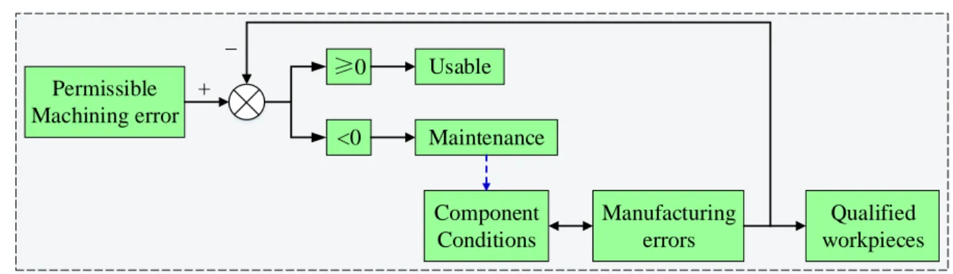
The system block diagram of the MEBM is exhibited in Fig. 1. It can be found that the MEBM resembles 16
a closed-loop control system, where the input of the maintenance system is the permissible machining error, 17
the real-time machining error of the machine tool is monitored as the feedback. When the monitored machining 18
error exceeds the permissible machining error, maintenance actions are initiated. With the aid of the closed-19
loop control, the machining accuracy can be guaranteed; besides, since the repairs will be taken properly at the 20
occurrence of excessive machining errors, the premature and redundant repairs can be avoided and 21
maintenance cost can be minimized. 22
It can be found that to construct the MEBM, the machining errors must be monitored in real time. There 23
are mainly two ways to determine the machining errors: indirect estimation and direct measurement. 24
(a) Indirect estimation: when the mapping relationship between the component condition and the machining 25
error has been derived, the machining error can be indirectly estimated from the condition of the component. 26
What’s more, under such situation, the related component is apparent and its satisfactory condition level can 27
6
(b) Direct measurement: when the mapping relationship between the machining error and its error source 1
is unbeknown, the machining error must be directly measured. In these cases, additional diagnosis techniques 2
are required to locate the related components. Of course, when the mapping relationship between the 3
component condition and the machining error is already known, direct measurement is also feasible. 4
It can be found that it is quite beneficial to develop the mapping relationship between component condition 5
and the machining error. First, it enables the indirect estimation of the machining error. Second, the related 6
component as well as its satisfactory condition level can be precisely determined inversely. 7
Component Conditions
Manufacturing errors Permissible
Machining error +
_
<0 Maintenance
0 Usable
Qualified workpieces 8
Fig. 1 The system block diagram of the MEBM 9
2.2 Two typical examples of the MEBM
10
2.2.1 The TBE-based maintenance 11
In [10], Tsai et al. employed the method of Angular Velocity Vold-Kalman Filtering Oder Tracking (AV 12
VKF-OT) to determine the ball pass frequency of the ball screw in the feed drive. Then, the preload loss of the 13
ball screw can be diagnosed by detecting the change of the ball pass frequency. Ultimately, once the onset of 14
preload loss is found, maintenance action is implemented. As we all know, the purpose of preloading the ball 15
screw is to reduce the clearance (the backlash) as well as the resultant machining error, and thus, to guarantee 16
the machining accuracy. However, when the preload has just been lost, the resultant machining error is actually 17
no bigger than the permissible machining error. This implies that it is too early to implement the maintenance 18
at the onset of the preload loss. 19
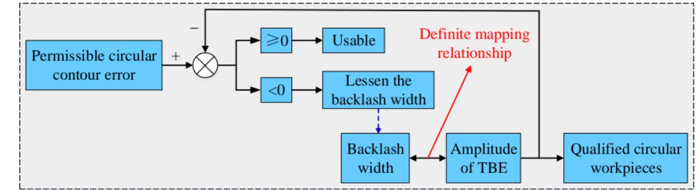
Based on the concept of MEBM, the TBE-based maintenance system can be developed as shown in Fig. 2, 20
where the machining error caused by backlash (e.g. the TBE) is monitored, and then, compared with 21
permissible machining error. When the amplitude of the TBE is larger than permissible machining error, repair 22
is carried out on the feed drive mechanical chain to lessen the backlash width. In [16], the mapping relationship 23
between the backlash width and the TBE is fully defined. Therefore, the TBE can be indirectly estimated from 24
7
It can be found that compared with the conventional CBM in [10], the TBE-based maintenance system is 1
capable of not only controlling the TBE in closed loop, but also minimizing the maintenance cost by avoiding 2
the premature repairs. 3
Backlash width
Amplitude of TBE Permissible circular
contour error +
_
<0 Lessen the backlash width
0 Usable
Qualified circular workpieces
Definite mapping relationship
4
Fig. 2 The system block diagram of the TBE-based maintenance 5
2.2.2 The spindle-error-based maintenance 6
Much attention has been paid on diagnosis techniques for seeking the fault signs of the bearings that are 7
critical components in the spindle subsystem. Up to now, various powerful methods have been proposed, for 8
example, the time and frequency domain analysis [13-14], the wavelet denoising [17], the spectral kurtosis 9
(SK), and the minimum entropy deconvolution (MED) [18]. However, unlike the diagnosis techniques, the 10
mapping relationship between the condition of the bearing and the performance of the spindle subsystem (e.g. 11
the spindle error) has rarely be researched. In other words, in the conventional CBM, the spindle error wasn’t 12
estimated, and therefore, couldn’t be guaranteed easily. In practice, for guaranteeing the precision of the 13
spindle, repairs are generally carried out once the signs of bearing defects are detected. As a consequence, the 14
spindle subsystem experiences extremely redundant maintenance, which takes immense expense. 15
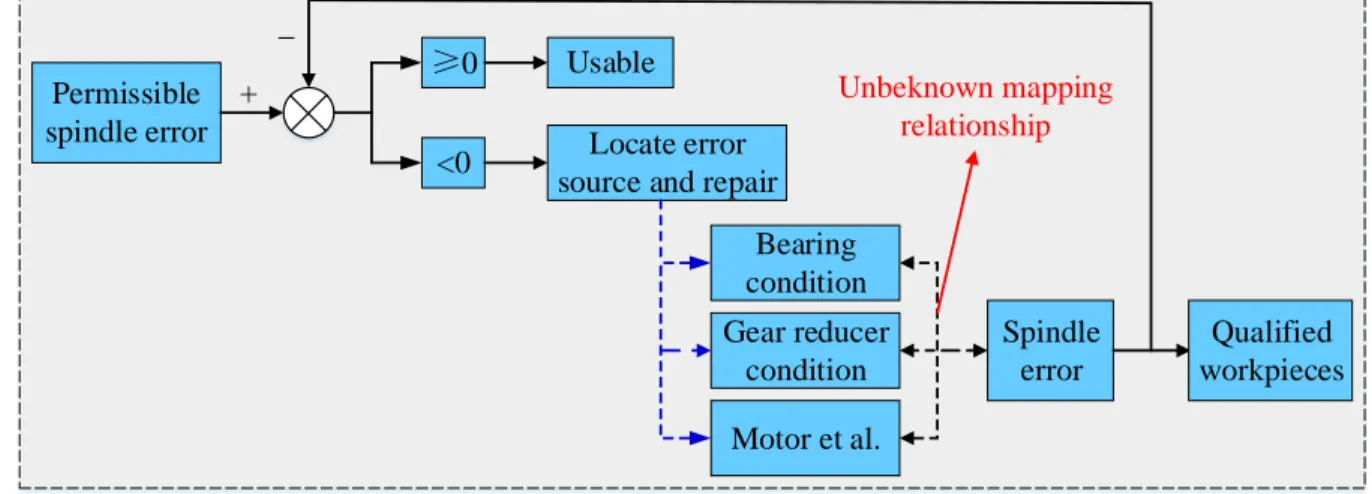
Based on the concept of MEBM, the spindle-error-based maintenance system can be developed as shown 16
in Fig. 3. Unfortunately, since the mapping relationship between the spindle error and its error sources remains 17
enigmatic, the spindle error could only be determined by direct measurement while indirect estimation is 18
infeasible; what’s worse, before implementing the maintenance, additional diagnostic analysis is still required 19
8
Bearing condition
Spindle error Permissible
spindle error +
_
<0 Locate error source and repair
0 Usable
Qualified workpieces Gear reducer
condition
Motor et al.
Unbeknown mapping relationship
1
Fig. 3 The system block diagram of the spindle-error-based maintenance 2
2.3 Key research points for the MEBM
3
From the discussion given above, it can be found that the newly proposed MEBM is initiated based on the 4
machining errors instead of the heuristic symptoms of the component defects. Therefore, the MEBM is not 5
only capable of controlling the machining accuracy by adopting the closed machining-error-control loops, but 6
also helpful to minimize maintenance cost by avoiding the premature and redundant maintenance. 7
However, in order to apply the MEBM strategy to machine tools, more attention still should be paid to the 8
following research points. 9
(1) Development of the mapping relationship between component condition and the machining error. 10
Section 2.1 shows that on one head, it enables the indirect estimation of the machining error; on the other hand, 11
the related component as well as its satisfactory condition level can be precisely determined inversely. 12
(2) Measurement of the component condition. Apart from the mapping relationship, in order to realize the 13
indirect estimation of the machining error, the component condition should also be measured in advance. 14
(3) Identification of the crucial machining errors. Ideally, for guaranteeing the machining accuracy of 15
machine tools, all of the machining errors should be monitored and controlled in closed loops. However, this 16
might result in a huge and costly monitoring system. Hence, to improve the feasibility and economy of the 17
MEBM strategy, the critical machining errors should be identified and paid more attention. In this paper, the 18
crucial machining errors refer to these that contribute most to the overall machining error and suffer severe 19
deterioration. 20
Based on the principle of MEBM, the construction method of TBE-based maintenance will be elaborated 21
9
3.
Measurement of mechanical chain accuracy and its deterioration mechanism
1
In order to construct the TBE-based maintenance, the backlash width should be measured first. By utilizing 2
the built-in encoders, this section will propose a method to evaluate the accuracy of the feed drive mechanical 3
chain, including the measurement of the backlash width and the lead error. The proposed method will only be 4
feasible for the full-closed-loop feed drives, where the position of the sliding table is directly measured by a 5
linear encoder to provide the position feedback while the rotating speed of the servomotor is picked up by a 6
rotary encoder and used as the speed feedback. 7
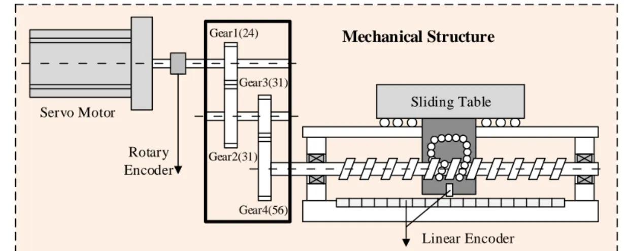
Fig. 4 shows the mechanical structure of Y-axis, on a vertical machining centre. It can be found that Y-axis 8
is a closed-loop feed drive. Its specifications are shown in Table 1. Unless otherwise stated all the experiments 9
will be conducted on this feed drive. 10
Sliding Table
Mechanical Structure
Servo Motor
Rotary Encoder
Linear Encoder
Gear1(24)
Gear2(31) Gear3(31)
Gear4(56)
11
Fig. 4 The mechanical structure of Y-axis 12
Table 1 Specifications of the mechanical chain in Y-axis 13
Item Value
Teeth number for Gear #1 Teeth number for Gear #2 Teeth number for Gear #3 Teeth number for Gear #4 Nominal screw pitch Transmission ratio 𝑘𝑎 Length of the useful travel
24 31 31 56
16 mm/rev. 6.857 mm/rev 1000 mm 14
3.1 Lead error
15
10
The lead error is the most commonly used index for characterizing the accuracy of the ball screw. In ISO 1
3408-3:2006, four criteria are defined for specifying the lead error of the ball screw [21]. In this paper, these 2
four criteria will be utilized to specify the lead error of the mechanical chain that consists of not only the ball 3
screw, but also a two-stage gearbox. 4
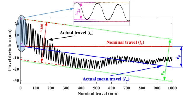
(1) Actual mean travel deviation 𝑒𝑝: the difference between the actual mean travel 𝑙𝑚 and the nominal 5
travel 𝑙0 over the full useful travel, as indicated by the blue dimension annotation on the right side. Here, 𝑙0 6
represents the nominal travel of the sliding table that can is given by the product of the servomotor travel 𝑥𝑚 7
and the transmission ratio 𝑘𝑎; 𝑙𝑎 refers to the actual travel of the sliding table 𝑥𝑙; and the actual mean travel 8
𝑙𝑚 indicates the straight line that has the best fit to 𝑙𝑎. In Fig. 5, the black solid line represents the actual travel 9
𝑙𝑎, the blue solid line means the actual mean travel 𝑙𝑚, and the red solid line indicates the nominal travel 𝑙0 10
that is also used as the reference coordinate (independent variable) of these three lines. 11
Please noted that for a clearer exhibition, when drawing Fig. 5, 𝑙0 has been subtracted from the three 12
dependent variables 𝑙𝑎, 𝑙𝑚, and 𝑙0. That’s why the nominal travel 𝑙0 keeps at zero over the whole travel, and 13
the vertical axis of the graph is labelled ‘Travel deviation’. 14
(2) Travel variation 𝑣𝑢: the band width (i.e. the range) of the travel variation over the whole useful travel, 15
as indicated by the two green dotted lines in Fig. 5. Here, the travel variation means the deviation between the 16
actual travel 𝑙𝑎 and the actual mean travel 𝑙𝑚, written as (𝑙𝑎− 𝑙𝑚). It can be found that (𝑙𝑎− 𝑙𝑚), over the 17
whole useful travel, is bordered by the two green dotted lines which are parallel to 𝑙𝑚. The distance between 18
the two straight lines equals 𝑣𝑢. Mathematically, 𝑣𝑢 can also be given by 19
𝑣𝑢= [max(𝑙𝑎− 𝑙𝑚) − min(𝑙𝑎− 𝑙𝑚)]|𝑢𝑠𝑒𝑓𝑢𝑙 𝑡𝑟𝑎𝑣𝑒𝑙 (1) 20
(3) Travel variation 𝑣300: the maximum band width of (𝑙𝑎− 𝑙𝑚) for any 300 mm travel over the whole 21
useful travel, as indicated by the two dashed red lines on Fig. 5. 𝑣300 is given by 22
𝑣300= max{[max(𝑙𝑎− 𝑙𝑚) − min(𝑙𝑎− 𝑙𝑚)]|300𝑚𝑚 𝑡𝑟𝑎𝑣𝑒𝑙}𝑢𝑠𝑒𝑓𝑢𝑙 𝑡𝑟𝑎𝑣𝑒𝑙 (2) 23
(4) Travel variation 𝑣2𝜋: the maximum band width of (𝑙𝑎− 𝑙𝑚) within any pitch travel over the full useful 24
travel, as indicated by the two pink dot dash lines on the partial enlarged view of Fig. 5. 𝑣2𝜋 can be written as 25
𝑣2𝜋= max{[max(𝑙𝑎− 𝑙𝑚) − min(𝑙𝑎− 𝑙𝑚)]|2𝜋 𝑡𝑟𝑎𝑣𝑒𝑙}𝑢𝑠𝑒𝑓𝑢𝑙 𝑡𝑟𝑎𝑣𝑒𝑙 (3) 26
In the full-closed-loop feed drives, when the feed drive is programed to take a one-way travel, the 27
11
the actual travel of the sliding table 𝑥𝑙 can be measured via the linear encoder. Thus, the nominal travel 𝑙0 can 1
be derived by 𝑘𝑎𝑥𝑚 and the actual travel 𝑙𝑎 just equals 𝑥𝑚. Based on the two travels 𝑙0 and 𝑙𝑎, the four criteria 2
𝑒𝑝, 𝑣𝑢, 𝑣300, and 𝑣2𝜋 can ultimately be derived for characterizing the lead error. 3
Fig. 5 shows the measurement results of the lead error in Y-axis on 2013-07-13. The four criteria were 4
𝑒𝑝= −18.29 μm/1000mm, 𝑣𝑢 = 37.18 μm, 𝑣300= 36.10 μm, and 𝑣2𝜋 = 22.00 μm, respectively. 5
Nominal travel (l0)
Actual travel (la)
Actual mean travel (lm)
e
pv
uv
3002
v
6Fig. 5 The lead error of the mechanical chain in Y-axis on 2013-7-13 7
3.1.2 Deterioration law of the lead error 8
To figure out the degradation law of the lead error in Y-axis, a long period of tracking measurement was 9
conducted. During the whole period, the machining centre was used as usual in an ordinary workshop without 10
the temperature control system. The utility time 𝑑 and the ambient temperature 𝑡 of each measurement are 11
shown in Table 2. 12
Table 2 Utility time 𝑑 and ambient temperature 𝑡 of each measurement 13
Measurement No. 1 2 3 4 5 6 7 8 9 Utility time 𝒅 (day)
Temperature 𝒕 (℃)
0 9 26 36 58 85 118 180 215 7 9 5 9 15 21 23 19 10 14
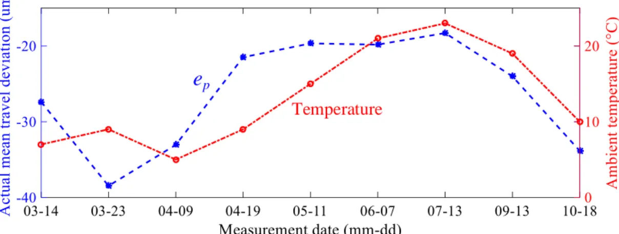
The mean travel deviation 𝑒𝑝 and the ambient temperature 𝑡 are displayed on Fig. 6; and the travel variations 15
12
Temperature
p
e
1
Fig. 6 Deterioration law of the actual mean travel deviations 𝑒𝑝 2
u
v
300
v
2
v
Temperature 3
Fig. 7 Deterioration mechanism of the travel variations 𝑣𝑢, 𝑣300, and 𝑣2𝜋 4
From Fig. 6, it can be found that during the tracking experiments, the actual mean travel deviation 𝑒𝑝 has 5
changed severely, from −38.47 μm/1000mm to −18.29 μm/1000mm, indicating that the resultant 6
machining error might also vary significantly. Therefore, the machining error caused by 𝑒𝑝 may need 7
monitoring. 8
Fig. 7 shows that compared with 𝑒𝑝, the changing range of the travel variations 𝑣𝑢, 𝑣300, 𝑣2𝜋 are much 9
smaller: for 𝑣𝑢 from 34.17 μm to 38.27 μm, for 𝑣300 from 32.5 μm to 35.96 μm, and for 𝑣2𝜋 from 10
22.00 μm to 25.23 μm. This indicates that the resultant machining errors might also change insignificantly. 11
In Fig. 6 and Fig. 7, it can also be observed that none of the four criteria increased monotonously. To verify 12
our observation more rigorously, the correlation coefficients between the criteria and the utility time 𝑑 are 13
worked out to be 𝑟𝑒𝑝_𝑑 = 0.1125, 𝑟𝑣𝑢_𝑑 = 0.6683, 𝑟𝑣300_𝑑= 0.6397, and 𝑟𝑣2𝜋_𝑑= 0.1337, respectively. The 14
13
𝑣2𝜋, while the relatively bigger correlation coefficients 𝑟𝑣𝑢_𝑑 and 𝑟𝑣300_𝑑 suggest that the deterioration of 𝑣𝑢 1
and 𝑣300 is related with the wear. 2
Similarly, the correlation coefficients between the criteria and the ambient temperature 𝑡 are also worked 3
out to be 𝑟𝑒𝑝_𝑡= 0.7044, 𝑟𝑣𝑢_𝑡 = 0.4223, 𝑟𝑣300_𝑡 = 0.5877, and 𝑟𝑣2𝜋_𝑡= −0.5207, respectively. It can be 4
found that the actual mean travel deviation 𝑒𝑝 is strongly correlated with the ambient temperature 𝑡: when the 5
temperature goes up, the pitch of the ball screw becomes longer. 6
Here, the Pearson product-moment correlation coefficient is adopted, written as 7
𝑟𝑋_𝑌=
cov(𝑋,𝑌)
𝜎𝑋𝜎𝑌 (4)
8
where cov(X, Y) is the covariance of X and Y; and 𝜎𝑋 is the standard deviation of X. 9
3.2 Backlash width
10
3.2.1 Measurement of the backlash width 11
Apart from the lead error, the backlash width is also a critical criterion for specifying the accuracy of the 12
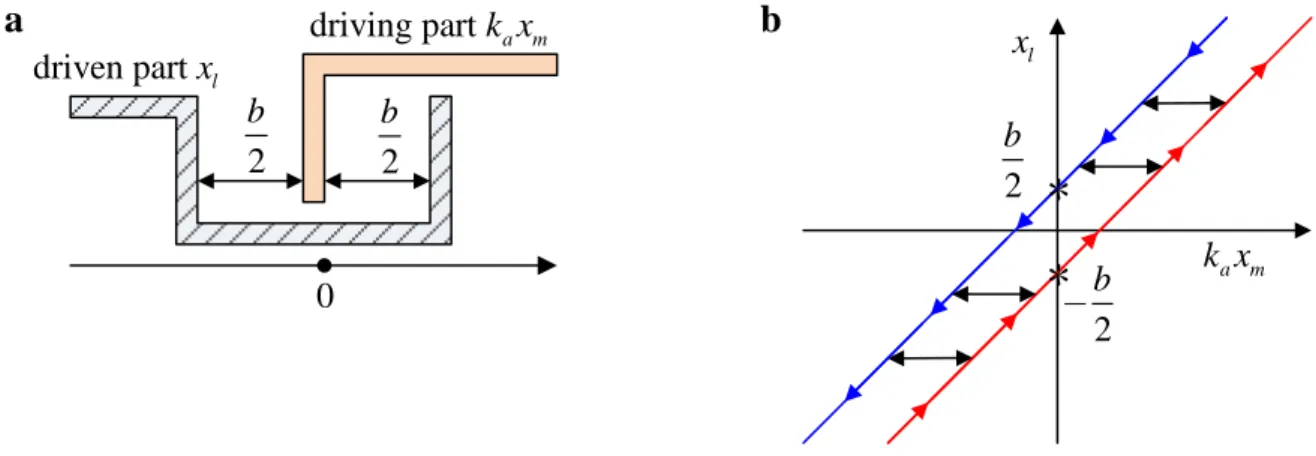
feed drive mechanical chain. The mechanical chain with backlash can be simplified as the friction-driven 13
hysteresis model as shown in Fig. 8 (a), where the servomotor as well as the transmission chain is assumed as 14
the driving part, the sliding table is assumed as the driven part, and the flexibility of the mechanical chain is 15
not considered. It can be derived that in this model, the motion of the driving part is given by the product of 16
the servomotor displacement and the transmission ratio 𝑘𝑎𝑥𝑚, the motion of the driven part equals the 17
displacement of the sliding table 𝑥𝑙, and the size of the total clearance is denoted by 𝑏, termed the backlash 18
width. Based on this model, the dynamic relationship between 𝑘𝑎𝑥𝑚 and 𝑥𝑙 can be derived: 19
{𝑥𝑙+ = 𝑘𝑎𝑥𝑚− 𝑏
2 𝑓𝑒𝑒𝑑𝑖𝑛𝑔 𝑝𝑜𝑠𝑖𝑡𝑖𝑣𝑒𝑙𝑦 𝑥𝑙− = 𝑘𝑎𝑥𝑚+
𝑏
2 𝑓𝑒𝑒𝑑𝑖𝑛𝑔 𝑛𝑒𝑔𝑎𝑡𝑖𝑣𝑒𝑙𝑦
(5) 20
14
a
2
b
2
b
driving part k xa m
driven part xl
0
b
2
b
2
b
a m
k x
l
x
*
*
1Fig. 8 The backlash element: (a) the structure schematic diagram and (b) the dynamic characteristics 2
Eq. (5) and Fig. 8 (b) indicate that when the servomotor arrives at a given position 𝑥𝑚, the sliding table is 3
possibly at the two different positions: 𝑥𝑙+ when feeding positively and 𝑥𝑙− when feeding negatively. As a 4
consequence, two separated lines are generated (see Fig. 8 (b)): the upward side 𝑘𝑎𝑥𝑚 ~ 𝑥𝑙+ as shown by the 5
red line and the downward side 𝑘𝑎𝑥𝑚 ~ 𝑥𝑙− as exhibited by the blue line. 6
Besides, from this model, it can be derived that the backlash width 𝑏 is equal to vertical distance between 7
the upward side line and the downward side line, i.e. the difference between 𝑥𝑙− and 𝑥𝑙+. 8
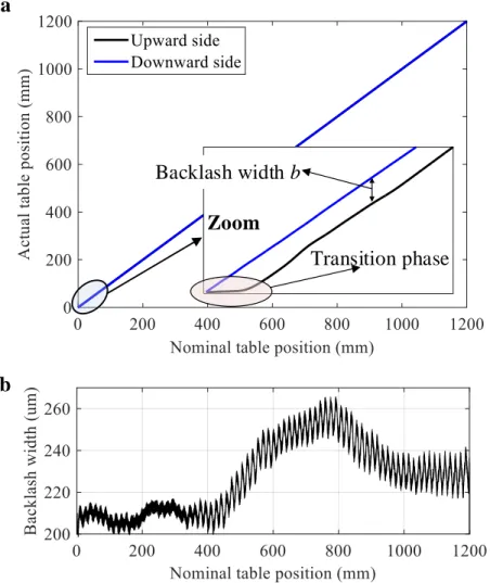
In the full-closed-loop feed drives, the motor position 𝑥𝑚 and the table position 𝑥𝑙 could be picked up from 9
the rotary and the linear encoders, respectively. Therefore, when the axis is programmed to make a round trip 10
over the measurement travel, the upward side 𝑘𝑎𝑥𝑚 ~ 𝑥𝑙+ and the downward side 𝑘𝑎𝑥𝑚 ~ 𝑥𝑙− can be obtained. 11
Based on this, the backlash width 𝑏 can be finally determined. 12
Fig. 9 shows the measurement results of backlash width in Y-axis on 2013-07-13. It can be found that the 13
backlash width is a position-dependent variable. 14
15
a
Zoom
Backlash width
b
Transition phase
1
b
2
Fig. 9 Measurement of the backlash width in Y-axis: (a) the upward side 𝑘𝑎𝑥𝑚 ~ 𝑥𝑙+ and the downward side 3
𝑘𝑎𝑥𝑚 ~ 𝑥𝑙− obtained from a round trip, and (b) the backlash width 𝑏 4
3.2.2 Deterioration law of the backlash width 5
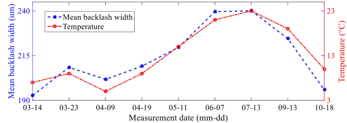
Similarly, the deterioration law of the backlash width was investigated. The arithmetic means of the 6
backlash width 𝑏̅ as well as the ambient temperature 𝑡 are plotted in Fig. 10. It can be found that during the 7
long-term measurements, the backlash width changed severely, increased in the early stages and then decreased 8
from July, which suggests that its resultant machining error might also change significantly, and therefore, 9
deserve monitoring. 10
The correlation coefficient of the mean backlash width 𝑏̅ with the utility time 𝑑 is worked out to be 𝑟𝑏̅_𝑑= 11
0.2411, implying that the backlash width hardly deteriorated due to the wear and erosion. Further, the 12
correlation coefficient between 𝑏̅ and the ambient temperature 𝑡 is worked out to be 𝑟𝑏̅_𝑡 = 0.9351, suggesting 13
that the change of the backlash widths has strong correlation with the temperature variation, similar as the 14
changing law of 𝑒𝑝. The phenomena could be explained by the thermal expansion theory: when the temperature 15
16
Consequently, when the temperature goes up, both the actual mean travel deviation 𝑒𝑝 and the backlash width 1
𝑏 increase. 2
3
Fig. 10 Deterioration law of the mean backlash widths 𝑏̅ 4
In this section, methods are proposed for measuring the mechanical chain accuracy. It can be found that in 5
the full-closed-loop feed drive, the two built-in encoders are ready for collecting the table and the motor 6
positions, which will then be used to derive the criteria of the mechanical chain accuracy. Hence, no extra 7
sensors are required. 8
From the long-term measurement results, it can be obtained that compared with the travel variations 𝑣𝑢, 9
𝑣300, and 𝑣2𝜋, the actual mean travel deviation 𝑒𝑝 and the backlash width 𝑏 fluctuated more greatly over time. 10
Through the correlation analysis, it can be revealed that the changes of 𝑒𝑝 and 𝑏 mainly resulted from the 11
ambient temperature variation, rather than gradual and irreversible wear and erosion. In practice, the 12
surrounding environment variations (especially the temperature variation) has often resulted in the 13
performance degradation of the high-precision instrument. 14
4.
Machining errors caused by the mechanical chain inaccuracy in the
full-closed-15
loop CNC machine tools
16
4.1 Identification of the crucial machining errors
17
Section 3 puts forward five indicators (including the backlash width 𝑏, the actual mean travel deviation 𝑒𝑝, 18
and the three travel variations 𝑣𝑢, 𝑣300, 𝑣2𝜋) for specifying the accuracy of the mechanical chain. However, in 19
17
indicators. Therefore, before implementing the MEBM, the indicators for specifying the mechanical chain 1
inaccuracy need to be mapped into the corresponding machining errors of the machine tool. 2
In practice, the natures and amplitudes of the machining errors caused by the identical mechanical chain 3
inaccuracy can be different depending on the types of the machine tools as well as the machining parameters. 4
In semi-closed-loop feed drive, since only a rotary encoder is installed on the shaft of the servomotor for 5
providing both the speed and the position feedback, the mechanical chain inaccuracy can result in positioning 6
errors. This paper mainly focuses on the full-closed-loop CNC machine tools, where the positioning errors are 7
completely eliminated. However, the mechanical chain inaccuracy can still result in the following machining 8
errors: 9
(1) Referring to [16], the backlash can result in the transient backlash error (TBE) at the start or directional 10
reversals, which is the one of the most predominant contour errors in the full-closed-loop CNC machine tools. 11
(2) As far as we know, few articles have been published for investigating the machining errors of the full-12
closed-loop CNC machine tools caused by the travel variations 𝑣𝑢,, 𝑣300, 𝑣2𝜋. Fortunately, we have 13
successfully conducted some simulations and experiments on a bi-axis contouring system. The results 14
demonstrate that the travel variations could bring about wavy contour errors to the machined profiles. However, 15
compared with the TBE, their amplitudes are much smaller. 16
(3) The actual mean travel deviation 𝑒𝑝 hardly degrades the manufacturing accuracy in the full-closed-loop 17
CNC machine tools. 18
Ideally, all the machining errors caused by the mechanical chain inaccuracy should be monitored and 19
controlled in closed loops. However, 𝑒𝑝 hardly affects the machining accuracy, and therefore, doesn’t deserve 20
the monitoring obviously. Both the backlash and the travel variations can lead to the machining errors. But, 21
the machining error caused by the backlash (i.e. the TBE) is much larger than the machining errors caused by 22
the travel variations. In addition, the long-term measurement results in Section 3 show that the backlash width 23
fluctuated much more severely than the travel variations. 24
Given all that, we can draw the following conclusion: in full-closed loop CNC machine tools, among all the 25
machining errors caused by the mechanical chain inaccuracy, the TBE is the most crucial one, and worth of 26
monitoring and controlling. 27
In [16], the mechanism and as well as the formulations of the TBE was investigated thoroughly, that will be 28
18
4.2 Review of the mapping relationship between the backlash width and the TBE
1
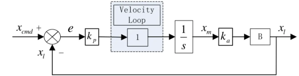
Fig. 11 exhibits the architecture of Y-axis. It can be found that Y-axis consists of three independent control 2
loops: the position-control loop, the velocity-control loop, and the current-control loop. Since the two inner 3
loops (the current-control loop and the velocity-control loops) generally respond much faster than the outer 4
loop (the position-control loop), the two inner loops can be idealized as units. In this way, a simplified model 5
for Y-axis could be derived as shown in Fig. 12, where B represents the hysteresis model of backlash. 6 Sliding Table Mechanical Structure Servo Motor Rotary Encoder Linear Encoder Gear1(24) Gear2(31) Gear3(31) Gear4(56) CNC Interpolator +
-e
(xm) -f i -Position Control Velocity Control Current Control cmd v + cmd i + cmd x l x Power Electronics Control Structure 7
Fig. 11 Architecture of the full-closed-loop Y-axis 8
9
Fig. 12 Block diagram of the simplified model for Y-axis 10
Owing to the employment of the full-closed-loop control, the positioning errors are completely eliminated. 11
However, when feeding direction reverses, the backlash in the mechanical chain can still postpone the motion 12
of the sliding table until the backlash is completely traversed. Based on the simplified model in Fig. 12, the 13
process of backlash traverse could be described by an integral function 14
∫ 𝑘𝑝𝑘𝑎𝑒𝑑𝜏 𝑇
0 = 𝑏 (6)
15
By solving Eq. (6), the delay time 𝑇 caused by backlash 𝑏 could be worked out. 16
If several axes are employed to move synchronously to sculpture a profile, the motion delay caused by 17
backlash can lead to the incoordination between axes, and consequently, the TBE. Here, we assume that a 18 B -+ 1
1
s
Velocity Loop cmdx
x
mx
l19
straight line is milled by a bi-axis (X-axis and Y-axis) contouring system, and at the beginning, the backlash 1
in Y-axis is directly engaged, and reversely engaged in X-axis. Under such assumption, TBE will emerge at 2
the initial phase as shown in Fig. 13 (a). Based on the simplified model, the analytical amplitude of the TBE 3
𝜀𝑏 on the straight line can be derived: 4
𝜀𝑏 = 𝑠𝑖𝑛𝜃√ 2𝑏𝑣𝑐𝑜𝑠𝜃
𝑘𝑎𝑘𝑝 −
𝑣𝑠𝑖𝑛𝜃𝑐𝑜𝑠𝜃
𝑘𝑎𝑘𝑝 [1 − exp (−√ 2𝑏𝑘𝑎𝑘𝑝
𝑣𝑐𝑜𝑠𝜃 )] (7)
5
where 𝜃 is the angle of the straight line to X-axis that is negatively engaged, 𝑣 is the federate, and 𝑘𝑎𝑘𝑝 is the 6
open-loop position gain. 7
When circular profiles are machined, TBE occurs at the quadrant transitions as shown in Fig. 13 (b). The 8
amplitude of the TBE 𝜀𝑏 can be derived: 9
𝜀𝑏 = 𝑅[√𝑐𝑜𝑠2(𝜙) + 𝑐𝑜𝑠2(𝜙)𝑠𝑖𝑛2(𝜔𝑇) − cos(𝜙)] (8)
10
where 𝑅 is the designed radius; 𝜔 is the angular velocity; 𝜙 is the phase shift of the feed drive system which 11
is a function of ω, given by 𝜙(𝜔) = −arctan ( 𝜔
𝑘𝑎𝑘𝑝); and the delay time 𝑇 is given by 12
𝑇 = real{ 1 𝑘𝑎𝑘𝑝[
(1−𝑖√3)𝐶
6 +
3(1+𝑖√3)
2𝐶 − 1]} (9)
13
where 14
𝐶 = √△+√△2−2916 2 3
(10) 15
with 16
△= 54 − 162𝑘𝑎𝑘𝑝𝑏
√(𝑘𝑎𝑘𝑝)2+𝜔2
𝑅𝜔2 (11)
17
a
20
b
1
Fig. 13 The transient backlash error (a) on a straight line and (b) on a circular profile 2
Thus, Eqs. (7) and (8) fully define the mapping relation between the backlash width 𝑏 and the TBE 𝜀𝑏 in 3
the full-closed-loop CNC machine tools respectively in cases of a line and a circle. For further information on 4
the mechanism of the TBE, please refer to [16]. 5
From Eqs. (7) and (8), it can be found that the TBE 𝜀𝑏 is determined by not only the backlash width 𝑏, but 6
also the machining parameters (including the type of the profiles, radius of circle, orientation of straight line, 7
feedrate, and so on). This implies that in order to calculate the TBE uniquely, the machining parameters should 8
be specified in advance. 9
Here, we assume such a machining task to be finished: a circular workpiece with radius of 200 mm is to be 10
milled by the XY contouring system; the open-loop position gains of both axes 𝑘𝑎𝑘𝑝 are equal to 10; and the 11
feedrate is 200 mm/min. Under such assumption, the one-to-one relationship between backlash width 𝑏 and 12
21
Warning threshold of TBE
Warning threshold of backlash width
1
Fig. 14 The TBE 𝜀𝑏 vs. the backlash width 𝑏 when machining a circle with a radius of 200 mm at 200 2
mm/min and their warning thresholds 3
5.
The TBE-based maintenance
4
5.1 The estimated TBE
5
In Section 3.2, the backlash widths in Y-axis were tracked and exhibited in Fig. 10. In Section 4.2, the one-6
to-one relationship between the backlash width 𝑏 and the TBE 𝜀𝑏 is derived and shown in Fig. 14. Based on 7
these foundations, the TBE, caused by the backlash in Y-axis, can be indirectly estimated ultimately, as 8
displayed in Fig. 15. 9
10
22
5.2 The warning threshold of TBE
1
As shown in Fig. 2, in the TBE-based maintenance system, apart from the real-time TBE should be 2
monitored as the feedback of the maintenance system, the permissible machining error is also needed to be as 3
the input of the maintenance system (namely the warning threshold of the TBE). 4
In general, the permissible machining error is determined by the user-specified tolerance of the workpiece. 5
In our example, it can be assumed that the contour error (roundness error) of the circular workpiece should be 6
smaller than 45 μm. This implies that the warning threshold of TBE equals 45 μm, as shown by the red dash-7
dot line in Fig. 14. 8
5.3 Implementation of the TBE-based maintenance
9
Up to now, the TBE as well as its warning threshold have been obtained respectively in Sections 5.1 and 10
5.2. Therefore, when the monitored TBE 𝜀𝑏 exceeds its warning threshold 45 μm, the maintenance system 11
will notify the maintenance workers to lessen the backlash width. 12
According to the one-to-one mapping relationship between the backlash width and the TBE as indicated by 13
the solid black line in Fig. 14, the permissible maximal size for the backlash can also be quantitatively deduced 14
to be 236.0 μm as indicated by the blue dash-dot line in Fig. 14. So, the value of 236.0 μm can be considered 15
as the warning threshold for the backlash width. 16
The backlash width can be lessened by reloading the ball-screw-nut assembly, reassembling the gearbox, 17
or replacing the mechanical chain. 18
From Fig. 15, it can be observed that in June 7th and July 13th, the monitored TBE were respectively
19
45.48 μm and 45.55 μm, larger than the permissible roundness error 45 μm. Therefore, for ensuring the 20
quality of the produced workpiece, the backlash in the mechanical chain should be lessened to stay within the 21
permissible size. 22
From Fig. 10, it can be found that the mean backlash width 𝑏̅ in June 7th and July 13th were respectively
23
239.5 μm and 240.1 μm, larger than the warning threshold of the backlash width 236.0 μm. Hence, an 24
identical maintenance decision can be obtained: the mechanical chain should be restored to make its backlash 25
width smaller than 236.0 μm. 26
In this way, the TBE-based maintenance system is finally established, where the real-time TBE is indirectly 27
estimated as the feedback of the maintenance system and the warning threshold of the TBE is customized 28
23
width of the backlash in the mechanical chain is measured by utilizing the built-in encoders and the mapping 1
relationship between the backlash width and the TBE was proposed in [16]. When the monitored TBE exceeds 2
its warning threshold, maintenance workers will be notified to lessen the backlash width, and meanwhile, the 3
permissible maximal size for the backlash will also be computed and informed. 4
It should be noticed that before constructing the TBE-based maintenance system, an investigation has been 5
carried out to prove that the TBE is crucial, which deserves to be monitored and controlled. 6
Compared with the CBM proposed in [10], the newly developed TBE-based maintenance system has the 7
following advantages. 8
(1) The TBE is monitored and controlled in a closed loop, and therefore, the quality of the produced 9
workpiece can be ensured. 10
(2) The maintenance action is triggered properly at the occurrence of the excessive machining error, and 11
therefore, premature repairs can be avoided and the maintenance cost can be minimized. 12
(3) Since the mechanism of the TBE has been thoroughly investigated, the maintenance actions can be 13
precisely implemented: first, to lessen the backlash in the mechanical chain; and second, the permissible 14
maximal size for the backlash could be quantitatively worked out. 15
(4) Apart from the built-in encoders, no extra sensor is required, and therefore, the cost for constructing the 16
TBE-based maintenance system can be quite low. 17
6.
Conclusions
18
(1) To overcome the drawbacks of the conventional CBM, this paper put forward the concept of the MEBM, 19
where the maintenance actions are initiated based on the machining errors rather than the heuristic symptoms. 20
In the MEBM, repairs can be taken properly at the occurrence of the excessive machining errors, and therefore, 21
the premature and redundant maintenance can be avoided and the maintenance cost can be minimized; what’s 22
more, the machining errors are controlled in the closed loops, and therefore, the machining accuracy can be 23
guaranteed. 24
(2) Based on the concept of MEBM, the TBE-based maintenance system was established. To achieve this 25
aim, first, encoder-based approaches were developed for specifying the accuracy of the mechanical chain, 26
which is available for the full-closed-loop feed drives. Thereafter, the mechanical chain accuracy was tracked 27
24
mean travel deviation 𝑒𝑝 and the backlash width 𝑏 fluctuate more significantly over time. Besides, the 1
correlation analysis revealed that the changes of 𝑒𝑝 and 𝑏 mainly resulted from the ambient temperature 2
variations. 3
(3) Then, the manufacturing errors, in the full-closed loop CNC machine tools, caused by the mechanical 4
chain inaccuracy are discussed, proving that the TBE is the most crucial error and worth monitoring and 5
controlling. Subsequently, the analytical mapping relationship between the backlash width and the TBE is 6
derived/reviewed. 7
(4) Based on the measured backlash width and its mapping relationship with the TBE respectively obtained 8
in Conclusions (2) and (3), the real-time TBE could be indirectly estimated. The warning threshold of TBE 9
was customized according to the permissible roundness error of the workpiece. Thus, when the monitored TBE 10
exceeds its warning threshold, the maintenance workers would be notified to lessen the backlash width, and 11
meanwhile, the permissible maximal size for the backlash could also be computed and informed. Hence, the 12
TBE-based maintenance system was fully completed, which is capable of controlling the TBE with minimal 13
maintenance cost. 14
Acknowledgments:
15
This research is supported by the National Natural Science Foundation of China (Grant nos. 51405373 and 16
51421004), which are highly appreciated by the authors. The authors wish to acknowledge Prof. Gang Jin at 17
South China University of Technology for his comments and suggestions that improved this work. 18
7.
References
19
[1] Nowlan FS, Heap HF (1978) Reliability-centered maintenance. United Airlines, San Francisco, 20
California 21
[2] Roy R, Stark R, Tracht K, Takata S, Mori M (2016) Continuous maintenance and the future–Foundations 22
and technological challenges. CIRP Annals-Manufacturing Technology 65(2):667-688 23
[3] Barlow R, Hunter L (1960) Optimum preventive maintenance policies. Operations Research 8(1):90-100 24
[4] Lee S, Ni J (2013) Joint decision making for maintenance and production scheduling of production 25
systems. The International Journal of Advanced Manufacturing Technology 66:1135-1146 26
25 Maintenance Engineering 1(3):3-17
1
[6] Waeyenbergh G, Pintelon L (2002) A framework for maintenance concept development. International 2
Journal of Production Economics 77(3):299-313 3
[7] Dekker R (1996) Applications of maintenance optimization models: a review and analysis. Reliability 4
Engineering & System Safety 51(3):229-240 5
[8] Wang H (2002) A survey of maintenance policies of deteriorating systems. European Journal of 6
Operational Research 139(3):469-489 7
[9] Jardine AKS, Lin D, Banjevic D (2006) A review on machinery diagnostics and prognostics 8
implementing condition-based maintenance. Mechanical Systems and Signal Processing 20:1483-1510 9
[10] Tsai PC, Cheng CC, Hwang YC (2014) Ball screw preload loss detection using ball pass frequency. 10
Mechanical Systems and Signal Processing 48(1):77-91 11
[11] Verl A, Heisel U, Walther M, Maier D (2009) Sensorless automated condition monitoring for the control 12
of the predictive maintenance of machine tools. CIRP Annals-Manufacturing Technology 58(1):375-378 13
[12] Park C, Moon D, Do N, Bae SM (2016) A predictive maintenance approach based on real-time internal 14
parameter monitoring. The International Journal of Advanced Manufacturing Technology 85:623-632. 15
[13] Hoshi T (2006) Damage monitoring of ball bearing. CIRP Annals-Manufacturing Technology 55(1):427-16
430 17
[14] Saravanan S, Yadava GS, Rao PV (2006) Condition monitoring studies on spindle bearing of a lathe. The 18
International Journal of Advanced Manufacturing Technology 28:993-1005 19
[15] Takata S, Kirnura F, van Houten FJAM, Westkamper E, Shpitalni M, Ceglarek D, Lee J (2004) 20
Maintenance: Changing Role in Life Cycle Management. CIRP Annals - Manufacturing Technology 21
53(2):643-655 22
[16] Shi S, Lin J, Wang X, Xu X (2015) Analysis of the transient backlash error in CNC machine tools with 23
closed loops. International Journal of Machine Tools and Manufacture 93:49-60 24
[17] Lin J, Qu L (2000) Feature Extraction Based on Morlet Wavelet and Its Application for Mechanical Fault 25
Diagnosis. Journal of Sound and Vibration 234:135-148 26
[18] Randall RB, Antoni J (2011) Rolling element bearing diagnostics—A tutorial. Mechanical Systems & 27
Signal Processing 25:485-520 28
26
[20] Shi S, Lin J, Wang X, Zhao M (2016) A hybrid three-probe method for measuring the roundness error 1
and the spindle error. Precision Engineering 45:403-413 2