Φ Abstract -- This paper presents the design optimization procedure of a high power-density, permanent magnet synchronous machine for industrial pump applications. The designed machine drives an electric, oil flooded pump. In order to achieve higher torque-density, a fractional slot machine (8 poles, 9 slots) with double layer (concentrated) winding has been selected after a preliminary trade-off study, which considered several slot/pole combinations and winding configurations. The developed machine provides low torque ripple and short end windings, which contribute to lower axial length and higher efficiency. The electromagnetic performances have been evaluated by using finite element method and the lamination geometry has been optimized through a genetic. The final results are presented highlighting the achieved design targets.
Index Terms— PMSM, high power density machine, finite element method, Genetic Algorithm (GA) optimization.
I. INTRODUCTION
he two main limitations on the performance of electrical machines are the magnetic and the thermal limits [1]. With advanced cooling methods, the latter can be significantly improved and thus improved torque and power densities can be achieved. Several thermal management systems exist including the method of having electrical machines immersed in a cooling agent, which of course gives excellent cooling capabilities.
However, the added cooling capability due to flooded machines is still not enough to guarantee an optimal electrical machine performance, especially in terms of high power, reliability, cost-effectiveness and efficiency [2]. A machine topology and configuration that guarantees a high power to mass and power to volume ratio, is a key design aspect, especially where the main constraint is the available space for the machine. One of the better machine technologies, available today is that of the Permanent Magnet Synchronous Machines (PMSM) [3]. In fact, PMSMs have significant advantages compared to other types of electric motors such as higher torque and power density, higher efficiency, simple structure and low maintenance [4]. This is then usually coupled to appropriate design and optimization procedures in order to achieve a machine which gives an optimal performance for a particular application. A wealth of literature exists which investigates design and optimization strategies for PMSMs [2, 5].
A. Al-Timimy, M. Degano, P. Giangrande, G. Lo Calzo, Z. Xu, M. Galea, C. Gerada and H. Zhang are with the Power Electronics, Machines drives and Control Group, the University of Nottingham, University Park, Nottingham, NG7 2RD, UK.
L. Xia is with the AVIC Flight Automatic Control Research Institute, Xi’an China.
A. Al-Timimy (e-mail: [email protected]) L. Xia (e-mail: [email protected])
This paper focuses on the design and optimization of a PMSM, used to drive an oil-flooded pump for a harsh environment application. The main objectives of the work are to achieve a machine design where torque, efficiency and reliability are considered the main design objectives. From the initial trade-off studies, an 8-slot / 9-pole PMSM was identified as the most promising topology.
The design requirements and constraints are highlighted in section II. An initial trade-off analysis of the electrical machines suitable for applications is presented in section III. A sensitivity analysis has been carried out by using a finite element (FE) analysis and it allowed identifying the machine parameters, which most affect the PMSM performance. In section IV the results of the sensitivity analysis are reported. A further step forward in the design process has been developed applying an optimization strategy, based on a genetic algorithm (GA) on the machine geometry [6]. Along with the FE method, which allows evaluating the electromagnetic performance, the thermal behavior has been taken into account during the optimization procedure by using a lumped parameter network. The results of the design optimization are shown in section V. Finally, section VI showing the initial target has been fully achieved and draws some practical conclusion.
II. DESIGN REQUIREMENTS AND CONSTRAINTS
This section presents the required specifications for the electrical drive (electrical machine, power converter and control system) which will drive the flooded pump.
A. Electromechanical performance and geometry
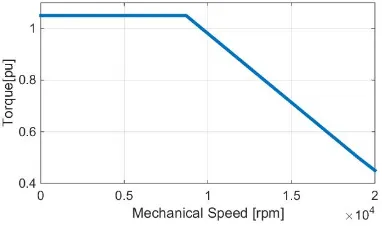
[image:1.595.324.515.625.738.2]In Fig.1 the torque-speed characteristics of the electrical machine are shown. A maximum continues torque has to be delivered within a speed range from 0 to 8700rpm. Beyond the base speed of 8700rpm, flux weakening is allowed until the maximum speed of 19000 rpm is required. From the operational duty cycle, it is at this top speed condition that the drive will mostly be operating in the application environment.
Fig. 1. Required torque-speed characteristics of the electrical machine
T
Design and Optimization of a High Power
Density Machine for Flooded Industrial Pump
The machine design needs to fulfil several constraints, such as the geometrical dimensions due to the restrained available space and the active parts weight. For this specific application, a low moment of inertia is required, in order to provide higher and fast acceleration of the machine shaft.
B. Power converter and control
Even if commonly considered as two separate units, the machine and the driving converter are closely related one with the other. In this sense, the converter specifications can be considered as input parameters for machine design. In this project, it was identified in the early stages that only conventional switching devices technologies could be used (i.e. no wide bandgap devices) thus relying on conventional IGBTs and silicon diodes. Such devices in the required range of power cannot usually be operated at switching frequencies higher than 16-18 kHz and requires, for safety reasons, dead times in the range of 2.5-3µs. The effect of dead times, as well known from the literature, is to reduce the effective voltage applied to machine windings by a constant proportional to the product of the dead time and the switching frequency.
Dead times can be easily compensated using conventional techniques as for example where an offset, proportional to the equivalent voltage loss is added relative to the reference signals in a PWM modulation scheme. This allows to greatly reduce the distortions in the currents waveforms during the zero-crossing, making them easier to be controlled from a control algorithm point of view. However, adding an offset means that the over modulation ‘area’ of the converter will be reached sooner that for an ideal converter without any dead time. Accordingly, the before mentioned voltage loss can be “reflected” to the DC-link value and taken into consideration for the machine design.Similar considerations can be done about voltage drops across power electronics devices (IGBTs and diodes).
Considering all the above, even if in the proposed application the DC-link voltage rated value is the conventional 270V, the machine has been designed considering the significantly lower voltage of 210V. This value comes from the previously discussed consideration about the converter characteristics and to compensate for other not modelled voltage losses due to cabling. Another important factor to be considered is the relatively low ratio between machine fundamental frequency (1.27kHz at 19krpm) and the switching frequency. Particular attention has to be focused on the THD of back-EMF voltages. In fact, apart from requiring a THD as lower as possible, it is important to direct the back-EMF harmonics toward the low frequencies (ideally around the third). This is intended to simply the control algorithm structure, as it is very challenging compensate for high frequency current harmonics with the limitations of the converter.
Based on those assumptions, the main design specifications are listed and summarized in Table 1.
TABLE 1 Design Specifications
Parameters Value Units
Dc link voltage 210 Vdc
Max. current ≦ 90 A
THD of BEMF ≦ 5 -
Moment of inertia ≦0.11×10 kg. m
Weight ≦ 2.75 Kg
Stack length ≦ 85 mm
Axial cross section ≦ 75×75 mm Max. temperature 200 °C Ambient temperature 70 °C
III. ELECTRICAL MOTOR SELECTION
The optimization design has been preceded by two trade-off studies: the first was oriented to identify the more suitable machine topology and the second was aimed to select the more convenient slot-pole combination and winding configuration.
According to the requirements listed in Table 1 and considering the specific application, some considerations can be done on different machine topologies, since each of them provides several pros and cons over other topologies. Following investigative studies such as presented in [7], the first trade-off study provides a useful qualitative comparison among different electrical machines such as Induction Machine (IM), Switched Reluctance Machine (SRM), Synchronous Reluctance Machine (Syn-RM) and PMSM including both Surface Mounted Permanent Magnet (SMPM) synchronous machines and Interior Permanent Magnet (IPM) synchronous motors. The preliminary analysis mainly focused on torque density, over all drive size, inertia, mechanical and thermal constraint. The results of this study are listed in Table 2.
TABLE 2
Qualitative Comparison between Different Machines
IM SPM SynRel SR
Rotor
Manufacturability ⨁⨁ ⨁⨁ ⨁⨁⨁ ⨁⨁⨁ Air-Gap sensitivity ⨀ ⨁⨁⨁ ⨀ ⨀
Torque ripple ⨁ ⨁⨁⨁ ⨀ ⨀
inertia ⨀ ⨁⨁⨁ ⨁⨁ ⨁
Torque density ⨁ ⨁⨁⨁ ⨁⨁ ⨁⨁
Overload Capacity ⨁ ⨁⨁⨁ ⨁⨁ ⨁⨁
Field Weakening ⨁⨁⨁ ⨁⨁ ⨁⨁ ⨁⨁⨁
Efficiency ⨁⨁ ⨁⨁⨁ ⨁ ⨁
Map key: ⨀ Bad, ⨁ Normal, ⨁⨁ Good, ⨁⨁⨁ Very good
Considering the above, the next step was to select the suitable configuration among the SMPM machines. Therefore, for the SMPM, different slot/pole combinations and winding configurations have been investigated for the specific application to satisfy the project requirements. Among the other slot/pole combinations, 8p/9s machine presents lower torque ripple, cogging torque, shorter end-windings which contribute to lower copper losses [12] and higher efficiency and higher torque density. Therefore, 8p/ 9s SMPM machine with double layer (concentrated) winding is considered for the rest of this work. It is well known [12, 13] that such slot/pole combination presents high rotor losses due to the harmonic-rich components for the armature reaction field. This indicates a topology whose performance is very sensitive to the air gap thickness dimension and attention must therefore be given to this aspect [12].
IV. PRELIMINARY DESIGN AND SENSITIVITY ANALYSIS
An initial sensitivity analysis on the main geometrical parameters of the 8p/9s machine has been carried out with the aim of defining a preliminary machine design as shown in Fig. 2.
Fig. 2. Cross-section of the 8p/9s PMSM
The sensitivity analysis has been applied on the main parameters of the 8p/9s machine topology (SMPM). Simultaneously the mechanical and thermal interactions have been considered. During the preliminary design study, the split ratio ( ), which is defined in (1), where and are the inner and outer stator diameter respectively, has been adapted to maximize the electromagnetic torque (T) and minimize the copper losses ( ).
⁄ (1)
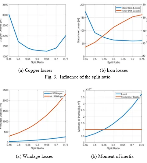
For a fixed output torque set at 1.05 pu, the split ratio with the lowest overall losses is selected. The lower copper losses will results in lower temperature and higher efficiency of the machine. Fig. 3 illustrates the effect of the split ratio on the machine losses where for the torque set to 1.05 pu, a minimum of 1250 W corresponding to of 0.65 are achieved. Also, the number of turns per coil has been changed in order to keep the output torque and back-EMF constant for different split ratios. Therefore, the copper losses will be higher for certain split ratios. Fig. 3 (b) shows the behaviour of the iron losses in both stator and rotor. This indicates that the bigger the the smaller the stator losses, with a constant trend for between 0.6 to 0.75. On the other hand, the rotor losses increasing almost linearly with the .
[image:3.595.308.549.219.487.2]
(a) Copper losses (b) Iron losses Fig. 3. Influence of the split ratio
[image:3.595.42.290.506.615.2]
(a) Windage losses (b) Moment of inertia Fig. 4. Influence of the split ratio
The same trend can be seen in Fig. 4. (a) and (b) where the windage losses and moment of inertia of the rotor are reported with respect of the Sr. In fact for a of 0.65, where the stator copper losses are minimum, the windage losses are very high (1300 W) and the moment of inertia is over the desired value. Considering the above, a split ratio of 0.57 has been selected as the best preliminary compromise. Reducing the split ratio by 12.3 % the windage losses and the moment of inertia decrease by 51.7 % and 54.4 % respectively. On the other hand, the copper losses increase only by 6.9 %. Such an increase is considered to be acceptable due to the significant reduction of windage losses and moment of inertia. After the optimal split ratio selection, a list of different parameters is optimized in an appropriate sequence, in order to satisfy the requirements of the project. The definitions of the design parameters are as follows: is the relative tooth width, is the relative stator back iron, is the relative magnet span, is the slot opening.
⁄ (2)
⁄ (4)
⁄ (5)
Where is the tooth width, is the tooth pitch, is the stator back iron, is the stator bore, is the magnet span, is the pole pitch, is the slot opening and is the slot pitch.
[image:4.595.45.286.148.249.2]
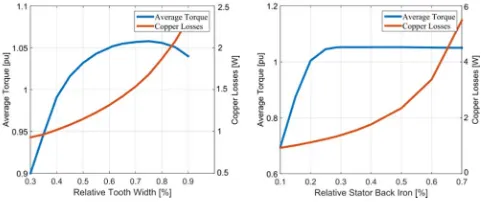
(a) Average torque and copper losses (b) Average torque and copper losses Fig. 5. Influence of the tooth width and stator back iron
[image:4.595.44.278.208.578.2]
(a) Average torque and torque ripple (b) Total harmonic distortion Fig. 6. Influence of magnet span
[image:4.595.45.280.291.406.2]
(a) Average torque and torque ripple (b) Total harmonic distortion Fig. 7. Influence of slot opening
In Figs 5 to 7, the influence of the parameters ( , ,
and ), is shown with respect to the machine performance in terms of developed torque, torque ripple and THD). These results indicate a geometry which provides a good compromise between acceptable values of torque, torque ripple, THD and copper losses is very hard to identify.
The optimal geometry is therefore defined and Table 3 reports the parameters and their respective boundaries. The best geometrical values carried out from this analysis are shown in the third column of Table 3. However, three important design requirements as highlighted in Table 1 are not satisfied. These are the moment of inertia is 16 % higher than the required value, and the total mass which is almost 8 % higher. In addition, the THD limit is not respected with a distortion of 7.5 %.
TABLE 3
Results from Sensitivity Analysis
Parameters Boundaries Best Value 0.45 – 0.75 0.57
35 – 95 % of 8.5 mm 10 - 70 % of 4.51 mm
90° - 171° 80 % 10 – 40 % of 3.35 mm
For this reason, a more refined optimization procedure of the electrical machine taking into account more variables becomes mandatory with the objective of finding the optimal solution.
V. MACHINE OPTIMIZATION
Due to the first design stage not having achieved all the required specification, then as a next step, a refined analysis and optimization scheme is defined. In order to achieve good accuracy for a minimum computational time, a genetic algorithm optimization is developed. Starting from the results carried out on the analysis described in section IV, the ‘new’ boundaries for the optimization are determined. Two parameters, such as rotor back iron ( ) and tooth tip ( ), are considered as new input variables in addition to the once used in section IV.
The design parameters and their boundaries are given in Table 4. The population size and the number of generations evaluated are 70 and 40 respectively.
These settings have allowed the optimization algorithm to converge in a reasonable amount of time. The initial population has been randomly created filling the design space with a uniform distribution. The optimization algorithm MOGA-II has been chosen with the aim of achieving a fast Pareto convergence. It is based on Multi Objective Genetic Algorithm (MOGA) and works on a set of design configurations which are periodically updated when one generation is completed [14]. The number of generations is 40, while the total number of iterations that are considered correspond to 2800. A new set of variables, selected among the boundaries reported in Table 4, is then reassigned and the FEA is carried out again for the next generation. The objective functions to be optimized are:
• Minimize (THD).
• Maximize (Average torque).
• Minimize (Losses).
[image:4.595.44.279.435.561.2]Fig. 8. Trend of the optimization results: scatter 4D reporting THD and average torque together with the total losses and split ratio Sr.
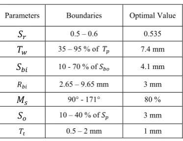
[image:5.595.73.260.342.486.2]Among the best solutions within the target area from the Pareto Front optimization, the optimal machine with torque equal to 1.05 pu, lower losses and THD is chosen. In Table 4 the geometrical parameters used as input variables for the optimization are reported. The third column is summarizing the geometrical for the selected machine.
TABLE 4
Input Design and Optimal Solution
Parameters Boundaries Optimal Value 0.5 – 0.6 0.535
35 – 95 % of 7.4 mm 10 - 70 % of 4.1 mm 2.65 – 9.65 mm 3 mm
90° - 171° 80 % 10 – 40 % of 3 mm 0.5 – 2 mm 1 mm
VI. MACHINE PERFORMANCE
In this section, the results obtained from the design and optimization of the 8p/9s PMSM is presented. The machine was optimized using Silicon Steel (SiFe) material (M270-35A), with lamination thickness of 0.35 mm and saturation limit of 1.7 T. Fig. 9, shows the flux density distribution in the stator lamination, where the flux density in the stator tooth approaches the 1.65 T which very close to the knee of the magnetization curve (saturation limit).
Fig. 9. Flux density distribution (1.05 pu @ 8700 rpm)
[image:5.595.309.540.371.485.2]Table 5 summarize the most important parameters of the designed machine for the two different operating conditions.
TABLE 5
General Machine Specifications
Performance Indicators 1.05 pu @ 8700 rpm 19000 rpm 0.5 pu @ Current density J ( ⁄ ) 37.2 RMS
Power density ( ⁄ ) 3.84
Efficiency (%) 87.2 82.4
Torque ripple (%) 0.6 0.5
Back-EmF THD (%) 4.7 4.72
Stack length (mm) 85
Moment of inertia ( . ) 1.
Fig. 10 (a) and (b) shows the performance of the optimal 8p/9s PMSM in terms of torque ripple and cogging torque at the base speed operating condition. At the high speed operating condition, the required torque of 0.5 pu is achieved with minimum torque ripple of 0.5%.
The waveform of the no load back-EMF is quite sinusoidal and the THD is shown in Fig. 11 (a) and (b), for both rated and maximum speed.
(a) Torque (b) Cogging torque Fig.10. PMSM performance comparison (1.05 pu @ 8700 rpm)
(a) Rated speed (8700 rpm) (b) Maximum speed (19000rpm) Fig.11. Phase voltage harmonics (THD)
A Samarium Cobalt material for the permanent magnet has been selected due to its lower temperature coefficient (highest stability). The chosen material for this specific application is Recoma 33E grade of (Sm Co which has the highest operating temperature and maximum energy product in the market whose demagnetization curves are shown in Fig. 12.
[image:5.595.308.546.516.643.2] [image:5.595.65.270.637.719.2]Fig. 12. Sm2Co17 demagnetization curves
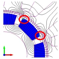
One of the main challenges with PM machine is the requirement to ensure that no partial or full demagnetization occurs for all operating conditions [15]. Thus a demagnetization prediction analysis is performed using finite element simulation. The risk of irreversible demagnetization occurs when the PM operating point goes down below the knee of the curves shown in Fig. 12. Even, in the worst case, with PM temperature set at 180 °C, only a small amount of irreversible demagnetization occurs.This is shown in Fig. 13, where the red circle color represents the irreversible demagnetized regions.
Fig. 13. Demagnetization predection at = 200 °C
VII. CONCLUSION
This paper highlighted the design procedure and optimization for high power density PM machine for a flooded industrial pump application. A sensitivity analysis has been applied to investigate the effect of the main geometrical parameters on the machine performance. In order to achieve the required specification for the application, a Genetic Optimization algorithm was used to determine the optimal parameters for the 8p/9s PMSM. An excellent performance of high torque with lower torque ripple and more sinusoidal back-EMF was achieved. In general it can be conclude that the design procedures presented in this paper have resulted in a machine design which satisfies the project requirements in terms of geometrical dimensions, weight and moment of inertia and respecting the thermal limitation.
The next steps for the project is investigating the effect of different numbers of cooling channels inside the slot on the maximum temperature generated (Hot Spot) and then machine manufacturing.
VIII. ACKNOWLEDGMENTS
The work presented in this paper was partially supported by the 2013DFA70510 MoST International Cooperation.
IX. REFERENCES
[1] M. Galea, C. Gerada, T. Raminosoa and P. Wheeler, "A Thermal Improvement Technique for the Phase Windings of Electrical Machines," in IEEE Transactions on Industry Applications, vol. 48, no. 1, pp. 79-87, Jan.-Feb. 2012.
[2] B. C. Mecrow et al., "Design and testing of a four-phase fault-tolerant permanent-magnet machine for an engine fuel pump," in IEEE
Transactions on Energy Conversion, vol. 19, no. 4, pp. 671-678, Dec.
2004.
[3] W. Cao, B. C. Mecrow, G. J. Atkinson, J. W. Bennett and D. J. Atkinson, "Overview of Electric Motor Technologies Used for More Electric Aircraft (MEA)," in IEEE Transactions on Industrial
Electronics, vol. 59, no. 9, pp. 3523-3531, Sept. 2012.
[4] C. Gerada, K. Bradley, C. Whitley and G. Towers, "High Torque Density PM Machines for High Performance Operation," Industrial Electronics Society, 2007. IECON 2007. 33rd Annual Conference of
the IEEE, Taipei, 2007, pp. 210-215.
[5] Ma Xiaohe et al., "Review of high speed electrical machines in gas turbine electrical power generation," TENCON 2015 - 2015 IEEE
Region 10 Conference, Macao, 2015, pp. 1-9.
[6] Y. Kano and N. Matsui, "A Design Approach for Direct-Drive Permanent-Magnet Motors," in IEEE Transactions on Industry
Applications, vol. 44, no. 2, pp. 543-554, March-april 2008.
[7] L. Papini, C. Gerada, D. Gerada and A. Mebarki, "High speed solid rotor induction machine: Analysis and performances," Electrical Machines and Systems (ICEMS), 2014 17th International Conference on, Hangzhou, 2014, pp. 2759-2765.
[8] J. Gao, Y. Yu and S. Huang, "Winding layers and slot/pole combination in fractional slot/pole PMSM—Effects on motor performance," Electrical Machines and Systems, 2009. ICEMS 2009.
International Conference on, Tokyo, 2009, pp. 1-4.
[9] P. E. Kakosimos, E. M. Tsampouris, A. G. Kladas and C. Gerada, "Aerospace actuator design: A comparative analysis of Permanent Magnet and Induction Motor configurations," Electrical Machines
(ICEM), 2012 XXth International Conference on, Marseille, 2012, pp.
2538-2544.
[10] Zhang, Zhiwei, and Libing Zhou. "Design And Rotor Geometry Analysis Of Permanent Magnet–Assisted Synchronous Reluctance Machines Using Ferrite Magnet." Journal of Electrical
Engineering 66.6 (2015): 311-316..
[11] J. B. Bartolo, H. Zhang, D. Gerada, L. De Lillo and C. Gerada, "High speed electrical generators, application, materials and design," Electrical Machines Design Control and Diagnosis
(WEMDCD), 2013 IEEE Workshop on, Paris, 2013, pp. 47-59.
[12] J. Gao, Y. Yu and S. Huang, "Winding layers and slot/pole combination in fractional slot/pole PMSM—Effects on motor performance," Electrical Machines and Systems, 2009. ICEMS 2009.
International Conference on, Tokyo, 2009, pp. 1-4.
[13] D. Gerada, D. Borg-Bartolo, A. Mebarki, C. Micallef, N. L. Brown and C. Gerada, "Electrical machines for high speed applications with a wide constant-power region requirement," Electrical Machines and
Systems (ICEMS), 2011 International Conference on, Beijing, 2011,
pp. 1-6.
[14] M. Degano, E. Carraro and N. Bianchi, "Robust optimization of a traction PMASR motor according to given driving cycles," Electrical
Machines (ICEM), 2014 International Conference on, Berlin, 2014,
pp. 270-276.
[image:6.595.121.217.377.472.2]X. BIOGRAPHIES
Ahmed Al-Timimy received his M.Sc. degree in Electrical Engineering from the University of Technology, Baghdad, Iraq in 2012. He is currently working towards his PhD in electro-magnetic and electrical machine design with Power Electronics, Machines and Control Group at the University of Nottingham. His main research interests are design and analysis of high performance electrical machines for aerospace applications.
Michele Degano received the Laurea degree in electrical engineering from the University of Trieste, Trieste, Italy, in 2011 and the Ph.D. degree in industrial engineering from the University of Padova, Padova, Italy, in 2015. He is currently a Research Fellow with the Power Electronics, Machines and Control Research Group, The University of Nottingham, Nottingham, U.K. His main research interests are in the design and optimization of permanent-magnet machines and reluctance and permanent permanent-magnet-assisted synchronous reluctance motors through genetic optimization techniques, in applications ranging from small to large power.
Paolo Giangrande was born in Monopoli, Italy, in March 1982. He received the Ph.D. degree in electrical engineering from the Technical University of Bari, Bari, Italy, in 2011. In 2008, he was a Marie Curie Intra-European Fellow at the University of Malta, Tal-Qroqq, Malta. Since January 2012, he has been a Research Associate with the PEMC Group, The University of Nottingham, Nottingham, U.K. His research interests include sensorless control of ac electric drives and intelligent motion control, as well as design, modeling, and parameter identification of electrical machines for aerospace applications.
Giovanni Lo Calzo received the Master's degree and the PhD degree from the University of ROMA TRE, Rome, Italy, respectively in 2010 and 2015.From 2010 to 2011, he was a Research Assistant with the University of Roma Tre. He is currently a Research Fellow with The University of Nottingham, Nottingham, UK, in the Power Electronics, Machine and Control Group. His research interests are mainly focused on power electronics converters for high speed machines, control and modelling of grid-tied and isolated inverters, output filter topologies.
Zeyuan Xu obtained his PhD in in mechanical engineering from the University of Manchester, England, in 2002. He subsequently worked as a researcher at UMIST, Brunel University and University of Nottingham. His main research interests are in turbulent thermofluid flow, heat transfer enhancement, thermal management of advance electrical motor and power electronics, and mechanical design of high speed electrical machine.
Michael Galea received his PhD in electrical machines design from the University of Nottingham, UK, where he has also worked as a Research Fellow. He is currently a Lecturer in Electrical Machines and Drives within the PEMC research group of the University of Nottingham. He is the Deputy Director of the Institute for Aerospace Technology at the University of Nottingham, where he is also a Lecturer in Aerospace Systems Integration. His main research interests are design, analysis and thermal management of electrical machines and drives.
Chris Gerada obtained his PhD in Numerical Modelling of Electrical Machines from the University of Nottingham, UK in 2005. He subsequently worked as a researcher at the University of Nottingham on high performance electrical drives and on the design and modelling of electromagnetic actuators for aerospace applications. He was appointed as Lecturer in Electrical Machines in 2008, an Associate Professor in 2011 and Professor in 2013. His core research interests include the design and modelling of high performance electric drives and machines. Prof. Gerada holds a Royal Academy of Engineering / Cummins Chair in Electrical Machines. He is also an Associate Editor for the Transactions in Industry Applications and is the Chair of the IEEE Industrial Electronics society electrical machines technical committee.
He Zhang received his B.Eng. degree from Zhejiang University, China, in 2002. He obtained the Ph.D. degree in electrical machines from The University of Nottingham, UK, in 2009. Then he joined the UK Water Research Centre, and worked on energy efficiency determination for motor drive system for two years. He is currently a Senior Research Fellow and Director of Best motion machine drive technology center within the Power electronics, Machines and Control research group in University Of Nottingham. His research interests include high performance electric machines and drives.