ORIGINAL ARTICLE
Review on the influence of process parameters
in incremental sheet forming
Shakir Gatea1&Hengan Ou1&Graham McCartney1
Received: 22 October 2015 / Accepted: 25 January 2016 / Published online: 23 February 2016
#The Author(s) 2016. This article is published with open access at Springerlink.com
Abstract Incremental sheet forming (ISF) is a relatively new flexible forming process. ISF has excellent adaptability to conventional milling machines and requires minimum use of complex tooling, dies and forming press, which makes the process cost-effective and easy to automate for various appli-cations. In the past two decades, extensive research on ISF has resulted in significant advances being made in fundamental understanding and development of new processing and tooling solutions. However, ISF has yet to be fully implement-ed to mainstream high-value manufacturing industries due to a number of technical challenges, all of which are directly relat-ed to ISF process parameters. This paper aims to provide a detailed review of the current state-of-the-art of ISF processes in terms of its technological capabilities and specific limita-tions with discussions on the ISF process parameters and their effects on ISF processes. Particular attention is given to the ISF process parameters on the formability, deformation and failure mechanics, springback and accuracy and surface roughness. This leads to a number of recommendations that are considered essential for future research effort.
Keywords Single-point incremental forming . Formability . Failure mechanisms . Springback . Surface roughness
1 Introduction
Incremental sheet forming (ISF) generally refers to a group of forming processes that may be characterised by localized de-formations, and these deformations are proceeded progres-sively on a certain path to cover the whole surface of the part. Depending on this definition, there are several types of ISF, such us spinning, shear forming, flow forming and single- or two-point ISF. In spinning, a roller is used to push a rotating blank gradually onto a mandrel to produce an axisymmetric shape with respect to the profile of the mandrel. A similar approach is used in shear forming, but it is designed to use a large force to produce a hollow or tubular part.
The main difference between spinning, shear forming and flow forming is in the thickness of the formed parts. Parts formed by spinning process show less change in thickness as compared with those formed by shear forming and flow forming processes. Several ISF techniques have been devel-oped to make use of computer numerical controlled (CNC) equipment. One of these methods, single-point incremental forming (SPIF), may be characterised by the action of a CNC milling machine tool that has a single-point contact with the sheet metal blank. The blank is fixed by a holder that remains at
the same height, as shown in Fig. 1 [1]. In this process, a
small-sized hemispheric tool moves along a user-defined path
and incrementally creates the desired shape [2].
One of the earliest research publications on ISF was by
Leszak in 1967 in a patent [4] at the time when a CNC
ma-chine was not yet technically feasible. In the late 1970s and early 1980s, the principle of asymmetrical incremental sheet
metal forming was first described by Mason and Appleton [5,
6]. They proved that the flexible forming of a sheet metal
workpiece was possible by using a hemispherical tool that can be moved along a three-axis CNC mill. Since then, many research papers have been published in this field. However, * Shakir Gatea
Hengan Ou
1 Department of Mechanical, Materials and Manufacturing
ISF is still under development in a number of areas requiring further research before this technology is used within industry, although the potential areas for applications have already been highlighted and clear advantages have been established as against conventional sheet metal forming techniques.
Recently, a number of review papers have been published to present overview on ISF processes. A comparison between traditional and modern sheet metal forming was presented by
Hagan and Jeswiet [7] to illustrate the different characteristics
of the ISF process. The modifications that have been made to conventional sheet metal forming such as spinning and shear
forming were described by Jeswiet et al. [8], and it was
fo-cused on an asymmetric single-point incremental forming (AISF), which provided a valuable guideline for designers
and manufacturers. Micari et al. [9] discussed some relevant
issues concerning SPIF. It was recognized that the geometrical accuracy is considered one key weakness of SPIF, which may be compensated for by tool path optimization. Six mecha-nisms were discussed by Emmens and van den Boogaard
[10] to understand the deformation mechanisms and
formabil-ity in ISF. It is found that the contact stress, bending-under tension and shear mechanisms play a key role in localized deformation whilst cyclic straining, geometrical instability and hydrostatic stress mechanisms have an effect in postpon-ing the growth of neckpostpon-ing. Hydrostatic pressure cannot ex-plain stability above the forming limit curve but might have
an effect on final failure. Emmens et al. [11] gave a
compre-hensive review of historical development of ISF, and they found that most patents refer to two-point incremental forming (TPIF) as a process, just one patent related to the formability. An overview of the current state of development of hybrid
AISF was presented by Taleb Araghi et al.[12]. It was
con-cluded that stretch forming combined with ISF and laser-assisted AISF can be used to improve the sheet thickness distribution and accuracy of the final part. With most of pre-vious reviews focusing on the historical development and de-formation mechanisms of ISF, it is considered a useful addi-tion to have a detailed review focusing on ISF process param-eters and their effects on the finished parts as this is believed to
be a specific area that is important to move the ISF-centred process to the next level of technological maturity.
Therefore, this review paper aims to provide a detailed analysis of a number of critical research issues of ISF. It dis-cusses the current state of fundamental understanding, techno-logical capabilities and limitations, recent developments and current research challenges with a particular attention given to the formability, deformation and failure mechanics, springback and accuracy and surface roughness.
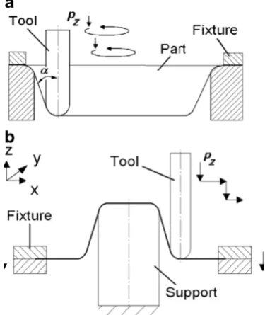
According to the forming method, the ISF technology can be classified as SPIF and TPIF, in which the tool moves around a partial or fully fixed die on a programmed path to
pull down the sheet. Figure 2 illustrates the TPIF process.
Further classification can be made by the types of processes that are applied, such as Negative or Positive. These types of
ISF processes can be seen in Fig.3. In Negative ISF, the force
is applied inside the cavity to be formed and the application of positive force is the outside of the part. The Positive process always happens in TPIF, where it is necessary to have a die that is located inside the part. This is because the tool force is applied on the convex side of the shape, to follow the contour lines. Negative increment sheet forming might be applied to both processes, depending on the component characteristics
[13].
According to the technical characteristics presented, SPIF can be used for small batch production, prototypes and customised products. For example, in the rapid prototyping,
Jeswiet et al. [15, ] used SPIF to produce prototypes for the
automotive industry. In the field of medical applications,
Verbert et al. [16] produced a titanium skull implant by using
multi-stage SPIF.
[image:2.595.54.291.51.190.2]The advantages that allow ISF to be developed as a viable solution for sheet metal products can be listed as follows: Fig. 1 Basic principle of incremental sheet forming [3]
[image:2.595.327.515.492.703.2]– The setup costs can be largely neglected [9]
– ISF is a highly flexible process, and it is possible to
sim-ply modify the machine part program so that the product
shape is changed [17].
– Due to the stress state induced during tool movement, the
formability is greater than that of traditional stamping [9].
– ISF is suitable to make parts for replacement, such as for
automotive parts where there is a lack of dies and tooling for a one-off part, and it can also be used for rapid
prototyping of new products [9].
– The contact surface is small, and the forces during the
forming process are low so the amount of lubricant re-quired is reduced as compared to conventional sheet
met-al forming [17].
On the other hand, there are some significant drawbacks of the process, which may be due to the following:
– ISF requires a significant amount of time to form the part
as deformation is processed gradually by the defined tool
path [9].
– The accuracy of the final part is normally inferior to that
in a conventional stamping process with a significant amount of springback to occur during tool movement and trimming of the blank.
– It is difficult to produce a part with a wall angle close to
90°, hence many stages of ISF forming are needed to
prevent failure [18].
– There are other limitations including material thinning
and poor surface finish.
This paper is organized as follows: Sect.2gives an
over-view of the ISF formability and the effect of process parame-ters on formability with suggested measures for improvement.
In Sect.3, a review and discussions are presented on the
me-chanical fracture and deformation mechanisms in SPIF.
Section4 introduces the shape distortion and springback
ef-fects arising from SPIF with detailed discussion on the effect of tool path, forming parameters and resultant residual
stress-es. Different algorithms are explained in Sect.5to improve the
surface finish of ISF processed parts. Finally, conclusions and
recommendations for future research are drawn in Sect.6.
2 Formability in SPIF
In general terms, formability in sheet metal forming is the ability of a given metal to deform without exhibiting specific forms of failure. Formability in SPIF can be defined by the
maximum wall angle (see Fig.4), and it is measured in terms
of a tangent line from the unformed blank to the deformed part
of the surface, determined by sine law,tf= tisin(π/2−) = ti
sinα, wheretiandtfare the initial and final thicknesses of the
part, respectively, andαis the semicone angle [19]. Thus, max
is usually used as a parameter to measure whether the SPIF Fig. 3 Forming principle of ISFaNegative forming andbPositive
forming [13]
[image:3.595.75.263.55.278.2] [image:3.595.232.540.553.710.2]process is a suitable forming application for a given material and sheet thickness.
There are different opinions about the modes of deforma-tion in SPIF. Based on experimental work and finite element (FE) simulation, some authors think that the deformation
oc-curs due to shearing [21], whilst others believe it is through
stretching [22]. In SPIF, a forming limit diagram (FLD) is
used to describe the formability of materials. The forming limit curve (FLC) is usually employed to determine the limits of proportional straining before failure and is quite different from the corresponding one in traditional forming, as shown
in Fig.5[23].
One of the main limitations of ISF is thickness reduction. A double-pass forming method was proposed by Kim and Yang
[24] to improve the formability of aluminium sheets in ISF. It
was shown that the majority of deformation occurs by shear, which is an important factor to improve the formability. More uniform thickness strain distribution of the respective products is possible when using the double-pass forming method than
with other methods. Myoung-Sup and Jong-Jin [2]
investigat-ed the formability of aluminium sheet (Al 1050) in ISF, using a tool with a freely rotating ball. It was found that the form-ability of the sheet shows a special shape on the strain path and appears as a straight line in the FLD. Forming limit diagrams were developed for ISF of 3003 aluminium sheet, using SPIF
by Young and Jeswiet [15]. FLDs were defined according to
five distinct shapes: a hemisphere, a straight-sided cone, a hyperbolic-sided cone, a pyramid and a shape with five lobes. It was noticed that very high strain of over 300 per cent can be
achieved with SPIF. Han and Mo [25] developed a
three-dimensional elasto-plastic finite element model to
investigate the 08Al ISF process. All results were compared with those of experiments. Good agreement between simulat-ed and experimental results in terms of the radial strain and thickness distribution was found. Furthermore, less thinning and more homogenous plastic strain and thickness distribution were achieved with reduced incremental step depth and
in-creased tool size and wall angle. Jun-chao et al. [26] carried
out numerical simulation and tensile tests of the thickness distribution and mechanical property of a truncated pyramid (Dc04 sheet). The results demonstrated that the minimum thickness was closely related to ISF tool diameter if a conven-tional tool path was employed and its location was largely determined by the step size. Tensile test samples were taken from the formed pyramid. It was found that the plasticity of sheet material dropped suddenly while the strength rose.
Junchao et al. [27] established a finite element model for a
double-pass forming to study the deformation characteristics of multi-stage forming of ISF. The blank was used in the experiment on a DC56 sheet, which showed that a double-pass forming process enabled more uniform thickness distribution, due largely to the benefits from the increase of the
total plastic deformation zone. Junchao et al. [28] devised a
series of multi-pass ISF experiments to study the effect of the number of forming stages (n) and angle increments between
two adjacent stages (Δα) on the DC56 sheet formability. It
was found that, with the increase of forming stages, the min-imum thickness rises significantly and more uniform thick-ness distribution is accomplished. Moreover, the maximum thickness reduction drops initially and goes up as the value
of Δαincreases. Titanium F67 grade 2 sheet was used by
Silva et al. [29] to determine the thickness distribution of
[image:4.595.231.544.467.708.2]formed sheet by using SPIF. The measurement of thickness and true strain showed that the limit wall angle of the titanium sheet with 0.5-mm thickness is 47°. In addition, the workpiece thick-ness is 0.35 mm according to sine law, as compared to approx-imately 0.25 mm from experiment. There are many factors which affect the formability of materials. However, the main factors in the SPIF include forming temperature, forming angle, step size, tool rotation, feed rate, tool size and tool path, and these will be considered in the following section.
2.1 Effect of process parameters on formability
2.1.1 Forming temperature
Studies have been undertaken to evaluate the effect of temper-ature on the formability of materials. A laser-based heating
system was used by Duflou et al.[30], to create a heated spot
in the moving contact zone between tool and titanium TiAl6V4 blank. The results showed that the formability of material was increased by laser-based heating. Ji and Park
[31] attempted to use magnesium sheets in incremental
forming at warm condition. It was found that with magnesium alloy, AZ31sheet formability increased as the temperature in-creased from 20 to 250 °C. The use of an electrical current for heating hard-to-form sheet metal at the tool-blank interface
was proposed by Fan et al. [32] for hot incremental forming,
as shown in Fig.6. It was found that when the electric current
was increased, the formability of hard-to-form sheet metal increased as well. Moreover, the yield strength in the tool-blank contact zone was reduced, so the wall angle and formability of magnesium alloy AZ31 increased. Recently, Liu et al. published a paper in developing electricity-assisted ISF by using new forms of ISF tooling with cooling channels to form titanium Ti6Al4V sheets with improved formability to
this hard-to-form material [33].
Göttmann et al. [34] introduced a new concept for
laser-assisted AISF, as shown in Fig.7. The tool path was
programmed by the CAX tool. Experimental results showed that the formability of the titanium grade 5 (TiAl6V4) alloy
increased. Mosecker et al. [35] investigated the temperature
effect on the microstructural evolution of the deformed work-piece. They formed longitudinal pockets with different depths by using a laser-assisted ISF. It was found that without cooling, deformation at 850 °C led to the highest deformation depth accompanied by pronounced hardening of the material due to grain refinement. On the other hand, good results were yielded from cooling to a coarse globular microstructure with lower hardness and nearly homogenous thickness reduction.
An apparatus was constructed by Adams and Jeswiet [36] to
improve the formability of 6061-T6 Al employing SPIF pro-cess. This apparatus can be used to apply large direct current to the rotating tool. Several current setting and tool diameters were tested to determine the maximum wall angle. It was noticed that the formability increased at the same current den-sity with different tool diameters, so the current denden-sity was considered to be a more important factor rather than the cur-rent magnitude. Therefore, a general condition is that the formability improves with the increase of forming tempera-ture, but this needs additional equipment (e.g. a heat source); therefore, it is suitable to use hot ISF only in cases where the cost is not taken into account.
2.1.2 Forming angle
In SPIF, the maximum forming angle is considered to be one
of the most important criteria to measure the material’s
form-ability limit. Two experiment designs were presented by Ham
and Jeswiet [37] to investigate the effect of forming
parame-ters in SPIF and the degree to which they affect aluminium AA3003 formability. The experiment showed a small effect of
[image:5.595.232.545.514.713.2]the step size on the maximum forming angle within 1° of
difference, whereas the material’s thickness, tool diameter
and interaction between the material thickness and tool size had a significant effect on maximum wall angle. Minutolo
et al.[38] determined the maximum slope angle of the
frus-tums of a pyramid and cone by forming aluminium 7075T0 sheet. The practical test program has led to an evaluation of the maximum wall angle: 63° for a frustum pyramid and 66° for a frustum cone. An experimental study was undertaken by
Bhattacharya et al. [39] to illustrate the effect of ISF process
variables on the maximum wall angle of an Al5052 blank. Analyses of experimental results indicated that the formable angle decreased with increased tool size and incremental depth and decreased blank thickness, whereas feed rate did not have a significant effect on the formable angle. Radu
[40] tested two geometries of parts and three thicknesses of
metal sheets in order to determine the maximum forming an-gle of a DC01 carbon steel sheet. It was possible to produce shapes with wall slope of up to 80° and a depth of up to 70 mm from sheet metal blanks no thicker than 1.2 mm by using a simple tool. The behaviour of brass 70/30 sheet under ISF
conditions was addressed by Fritzen et al.[41] with the
con-sideration of the following parameters: wall angle, step depth and tool path strategy. Experimental tests explained that the spiral tool path yielded a greater forming angle as compared with the traditional tool path. It can be seen from the above investigations that many parameters have a big effect on the wall angle, e.g. tool diameter and tool path, although further study is needed in order to determine the range of their effects on the wall angle (e.g. step size and feed rate).
2.1.3 Incremental depth (step size)
The influence of incremental depth is still a debatable param-eter. Theoretical investigation was achieved by Ambrogio
et al. [42] to get a deeper understanding of the basic
phenom-ena involved in SPIF. The analysis showed that a negative stress distribution occurs under the tool contact zone and
tensile stresses on the walls of the formed part. These stresses decrease with decreased incremental depth. Ham and Jeswiet
[37] studied the formability of aluminium AA3003 sheets in
two new experiment designs in SPIF, and they found that the incremental depth had a significant influence on the formabil-ity and that decreased step size improved the likelihood of the
part to be formed. Kim et al. [43] studied the ISF process to
produce a complex geometric shape (human face) by using FE
simulation and Taguchi’s method. Finite element method
(FEM) simulation was implemented and evaluated from the historical strain and stress values of cold rolled steel. FE re-sults based on the Taguchi array showed that the tool downstep was identified as an important factor for improving the formability. The effect of some parameters, such as step size, on the formability of a commercially pure titanium blank
was investigated by Hussain et al. [44], and the results proved
that the formability decreases linearly as the step size in-creases. Experimental investigation by means of surface 3D
digital image correlation was published by Decultot et al. [19]
in forming of an AW-5086-H111-grade aluminium alloy. It was found that the workpiece formability was reduced with the increase of increment step size. An experimental study using aluminium Al3003-0 was undertaken by Duflou et al.
[45] to measure the force in SPIF. It was noticed that the
vertical step size had the least significant impact, according
to the study by Fritzen et al. [41] to address the behaviour of
30/70 brass sheet in ISF. When the vertical step was decreased to 0.5 mm, there was a gain of 1° in the forming angle with a 100-mm depth without failure. It can be concluded that there is a gap of understanding on the influence of step size in ISF. Hence, more research needs to be carried out into the effect of different materials in order to find the relationship between step size and the formability of different materials.
2.1.4 Forming speed (rotation and feed rate)
Forming speed has a considerable influence on sheet formabil-ity with both rotational speed and feed rate considered impor-tant factors in SPIF. The relative motion between the tool and blank is directly proportional to the heat generated by friction. However, it is generally believed that the formability increases along with the forming speed due to heating effects. Ham and
Jeswiet [37] presented two experimental designs to investigate
the formability of aluminium AA3003 sheets in SPIF. Tool setups were at higher rotational speeds and thus generated more frictional heating in the contact zone, and it was found that the higher rotational speed improved formability. In addi-tion, the blank formability is improved by reducing the feed rate. Producing dome geometry by SPIF was studied by
Rattanachan and Chungchoo [46] to explain the effect of
speed on the formability of DIN 1.0037 steel (St 37-2 steel). The results showed that the tool rotational speed had more influence on formability and that when tool rotational speed Fig. 7 Experimental setup laser spot, forming tool and the procedure for
[image:6.595.53.290.51.193.2]increased, the formability decreased. On the other hand, the tool feed rate had less influence on formability, with the results showing decreased formability at increased feed rate. A cold
incremental forming process was carried out by Hussain et al.
[44] in order to investigate the effects of some parameters on
formability (maximum wall angle) of commercially pure tita-nium (Cp Ti) sheet. It was observed that an increase in the feed rate decreased the formability and that the relationship be-tween feed rate and maximum wall angle was in a quadratic
curve. Buffa et al. [47] proposed a method for enhancing the
formability of materials in SPIF using high tool rotation speed. This technique was applied on poor formability materials at room temperature, e.g. aluminium AA1050-O, AA1050-H24 and AA6082-T6 sheets. The experimental results showed that there was an increase in drawing angle around 7.5° to 12.5°, as compared to conventional SPIF process. It can be clearly seen that the effects of tool rotation are debatable. Therefore, there is a clear need for further research to the effect of tool rotation on ISF formability to establish a quantitative tool rotation and feed rate for different materials. The establishment of such a quantitative relationship would help provide a guideline of the optimum tool rotation and feed rate for a given material.
2.1.5 Tool size and shape
Tool size is an important factor on the formability of materials in SPIF. Experiments have proven that a smaller tool radius enables a higher formability than can be achieved by a larger one. Furthermore, better support of sheet metal can be obtain-ed with large tool diameters, due to a bigger contact zone, and the amount of forming force increases when the contact area increases between the tool and blank. In the case of a small tool radius, there is a highly concentrated zone of deformation that causes high strain and leads to better formability. Hussain
et al. [44] evaluated the formability of a Cp Ti sheet in cold
ISF process in order to investigate the effect of tool diameter on the formability. The tool diameter was varied over three levels, i.e. 8, 12 and 16 mm. It was found that by increasing the tool size, the formability decreases to approximately fol-low a quadratic relation.
Using a finite element model to investigate ISF of 08Al
sheet, Han and Mo [25] found that reduced incremental
depth and increased tool size and wall slope angle tend to reduce axial stress and material thinning and lead to more homogeneous distribution of thickness and plastic strain. The effect of tool diameter on the thickness was studied by
Jun-chao et al. [26]. They found that the tool size showed
little correlation to the location of the minimum thickness, but when tool diameter increases with a spiral tool path, the
thickness increases continuously (Fig. 8). Moreover, the
minimum thickness is closely associated with tool diame-ter if a conventional tool path is employed.
Ham and Jeswiet [37] illustrated the effect of tool diameter
on the maximum forming angle for SPIF of aluminium AA3003 sheets and found that higher formability occurred with smaller forming tools due to the concentration of friction heat at the forming tool tip.
A Box-Behnken design of experiment was used by Ham
and Jeswiet [48] to develop the experimental plan and to
an-alyse data, and the results were presented as a response surface graph, which showed the effect of factors on the forming limit. It has been shown that when comparing the influence of ma-terial type on average effective strain, with the AA6451 hav-ing the lowest average effective strain when comparhav-ing tool diameter to average effective strain, aluminium AA5754 seems to have no effect as the contour is flat. With aluminium AA645 sheet, the largest tool diameter generates lowest aver-age effective strain, and the other tool sizes have no effect on average effective strain.
A new oblique roller ball (ORB) tool has been developed
by Lu et al. [49] to investigate the influence of friction on the
material deformation and formability. Four grades of alumin-ium sheets were utilized in the experiments including AA110, AA2024, AA5052 and AA6111. A small hole in the sheet was drilled to study material deformation under both traditional rigid tool and the ORB tool. Experimental results showed that higher formability and smaller through-thickness shear are obtained with the ORB tool.
2.1.6 Tool path
Tool path generation is one of the most important factors that must be taken into account in ISF. It plays an impor-tant role to the final outcome, especially on thickness distribution of the formed product. Several types of tool
paths were tested by Yamashita et al. [50] in order to
[image:7.595.331.519.50.198.2]travelling tool should be started from one of the corners of the product for a better shape. Otherwise, it is better for the tool to move in the horizontal and vertical directions simultaneously (i.e. in a helical manner) to get more uni-form thickness distribution in the product. Mechanism of
NC sheet metal in the ISF was presented by Zhou [51].
Due to the fact that the deformation of the blank occurs only around the tool tip and the contact area (deformation region) and is subject to stretch deformation, the thickness of the deformed area of the sheet reduces and the surface area increases. The purpose of sheet metal forming in steps is to produce the whole sheet deformation. From experimental results, in the case of the parallel line tool trajectory, a uniform thickness distribution of the de-formed part is maintained and correlates with that obtain-ed by sine law. Tool path optimisation was determinobtain-ed by finite element method in corporation with a response sur-face method (RMS) and sequential quadratic
program-ming (SQP) algorithm, by Azaouzi and Lebaal [52], in
order to improve thickness distribution of an asymmetric
part. It was observed that after the third iteration, the optimal solution provided an improvement of about 7 %
the sheet thickness distribution (Fig. 9).
In order to overcome the problem related to inhomoge-neous thickness distribution in aluminium AA1050-O part,
an optimisation model was defined by Luigino et al. [17] to
optimise tool path design by using a new trajectory according to the decremental slope differential of ±10°. Significant re-duction in the localised thinning was observed when com-pared to both the non-optimised tool path and the optimised
one (Fig.10).
Experiments were carried out by Liu et al. [53] to
investi-gate and understand the formability and forming process mechanism of aluminium AA7075-O sheets in SPIF process. No difference was noticed in formability when the same part was formed with helical and Z-level tool paths. In addition, the same resultant force was obtained with both tool paths, but the force curve was smoother with the helical tool path.
3 Deformation and failure mechanics in SPIF
In sheet metal forming, the failures occur due to a number of mechanisms including the following: (A) void nucleation and coalescence; (B) shear band formation and (C) necking
insta-bility [54]. So, to understand how failure develops in SPIF,
deformation modes and states of strain and stress in the defor-mation zone should be known. In SPIF, there is more than one
deformation mode, as shown in Fig.11, including the
follow-ing: (A) plane strain stretching conditions in flat surfaces; (B) plane strain stretching conditions in rotational symmetric sur-faces and (C) equal bi-axial stretching conditions at corners. Additionally, there are possibilities of other deformation
modes between these modes [55].
[image:8.595.51.289.49.227.2]There are many ways to predict the onset of failure in sheet metal during forming processes, such as the FLD; forming Fig. 9 Sheet thickness distribution as a function of depth [52]
[image:8.595.177.545.518.702.2]limit stress diagram (FLSD); Müschenborn-Sonne forming limit diagram (MSFLD) and Marciniak-Kuczynski (M-K)
criteria [56]. However, the FLD is considered the most
well-known way of predicting failure in the ISF. Using the deformation mode, many researchers have tried to investigate the difference between the failure mechanisms of traditional sheet metal forming and ISF so as to give a specific answer to
the question,“Does necking occur before fracture in ISF?”, or
“Does fracture take place without necking?”Therefore, this
section is focused on the most studied deformation and failure mechanisms and the effect of key variables on failure.
3.1 Effect of process parameters on deformation and failure mechanics
3.1.1 Stresses and strains in SPIF
Stress triaxiality is used as a measure to consider the stress
state’s influence on failure modes, and strain represents one of
the most important criteria to predict damage in SPIF. A the-oretical model for the different modes of deformation is com-monly found in SPIF, built upon membrane analysis and
duc-tile damage mechanics by Martins et al. [55]. Experimental
observations show that fracture is not preceded by localized necking, and the crack develops under tensile meridional
stresses acting under stretching conditions (Fig.12).
Another analytical model of SPIF was presented by Silva
et al. [22] depicting membrane analysis and the experimental
observation of the smear mark in the contact zone between the tool and sheet. This model proved that the cracks in SPIF were
initiated by meridional tensile stresses but not by plane
shear-ing stresses as shown in Fig.13.
Specially prepared copper sheets were utilized by
Jackson and Allwood [57] to experimentally examine
the deformation mechanism of the ISF (SPIF and TPIF) and the accuracy of the sine law for prediction of wall thickness. The experimental results show that, firstly, the deformation mechanisms of both SPIF and TPIF happen in two planes: the first one perpendicular to the tool di-rection and the other parallel to the tool didi-rection. Stretching and shear occurred in the first plane, and shear in the second plane. Secondly, the high percentage of stretching and shear in the tool direction accounts for differences between the sine law and measured wall thick-ness in SPIF and TPIF. Finally, the mechanisms of SPIF and TPIF differed from a mechanism of pure shear. Experimental work using a surface 3D digital image
cor-relation approach was carried out by Decultot et al.[19]
to show that the fracture occurred in the uniaxial stretching domain. To predict the occurrence of failure
in the aluminium AA5052 sheet, Malhotra et al.[58] used
e x p l i c i t f i n i t e e l e m e n t a n a l y s i s ( F E A ) w i t h a damage-based fracture model, in which failure envelope depended on the hydrostatic pressure and the Lode angle. It was noted that the damage evolution was controlled by local bending around the tool and through-the-thickness shear. A fracture model combined with finite element analyses to predict the occurrence of fracture in SPIF
was carried out by Malhotra et al. [59] for two shapes—
a cone and a funnel. An aluminium AA5052 sheet was u s e d i n t h i s s t u d y . I t w a s f o u n d t h a t b o t h through-the-thickness shear and local bending of the sheet around the tool had an effect on fracture in the SPIF technology. By using a newly developed solid-shell ele-ment, a preliminary study of the stress state was carried out to evaluate a near-to-failure SPIF cone by Guzmán
and Habraken [60], for aluminium AA3003-O sheet. The
results showed that the Lode angle can be used with Voce or Swift hardening, and it is able to capture the stress state change during SPIF. Furthermore, an experimental and
numerical study was undertaken by Xu et al. [61] to
[image:9.595.53.289.54.177.2]in-vestigate the effect of through-the-thickness shear on the formability of aluminium AA5052-H32 sheet in SPIF. A fracture model was developed to simulate a 70° cone by SPIF and deep drawing. As a result, the fracture depth of the cone produced by SPIF was bigger than that of the same cone formed by deep drawing. Therefore, the through-the-thickness shear in deep drawing can be neglected as it is not significant as compared to that ob-tained in SPIF. In addition, the higher value of through-the-thickness shear in SPIF raises the value of the reference fracture strain, which results in lower dam-age accumulation. As a result, the through-the-thickness Fig. 11 Instantaneous deformation zone and contact area between
forming tool and workpiece during SPIF [55]
[image:9.595.76.263.623.690.2]shear in SPIF is considered as a positive factor to material
formability when it is within a certain range. Fang et al.
[62] proposed an analytical model from their study to
investigate the deformation mechanism and fracture be-haviour in the SPIF technology. Both the bending effect and the strain hardening were considered based on the equilibrium approach. The result showed that the defor-mation takes place mainly in a meridional direction and small amounts of deformation occur in the circumferential direction. These deformations occur not just in the contact area but also on the inclined wall, and the fracture always occurs on the outer surface of the wall at the transition point between the contact and non-contact zones. It is clear from the above discussion that there is not a unified theory for failure in SPIF; due to the contradicting views on the effect of shear on fracture, some researchers con-firm its important role in fracture with opposing views by others. Therefore, future work should focus on the frac-ture mechanism in ISF so that a unified model may be developed to accurately predict fracture in SPIF.
3.1.2 Application of a forming limit diagram
Depending on crack morphology and thickness measure-ments along the cross-section of the parts manufactured by SPIF, plastic deformation is revealed by uniform thin-ning until fracture, though there is no experimental evi-dence of necking taking place. Therefore, the forming limit curve at the necking (FLCN) of traditional sheet metal forming is not applicable to describe SPIF failure. Forming limit curve at fracture (FLCF) can be used to
predict the fracture in ISF [23, 63]. Most of the FLCs in
ISF at fracture take the shape of a straight line with a
negative slope in the first quadrant of the FLD. Ductile fracture criteria used in bulk forming processes are uti-lized to describe the FLD at fracture. The main idea of ductile fracture criteria is that the fracture happens when the maximum damage value of sheet metal exceeds a
crit-ical damage value (CDV) [64]:
Z εf
0
F process parametersð Þdε¼CDV ð1Þ
whereεfis the effective strain at fracture andFis a function of
the process parameters.
Based on ductile damage mechanics, Martins et al.[20]
investigated the forming limit of aluminium AA1050-H111 sheet in SPIF. It was demonstrated that neck formation did not precede fracture. Therefore, the conventional FLC is not applicable when describing failure. Instead, a fracture FLD should be employed. Finite element method, combined with
circle grid analysis, was used by Araujo et al. [65] in order to
explain failure by cracking at the critical geometric features of facial implants and to assist in the overall design of a titanium grade 2 sheet. The fracture limit curves by cracking are characterised by means of a straight line with a slope equal
to−0.8 and a maximum drawing angle of approximately 60°.
[image:10.595.152.544.51.288.2]In experimental testing, due to the fact that the maximum forming angle of titanium grade 2 has a rather low value, the side walls that surround and support the region of the sheet where the implant is located tend to crack and fail at a rather low angle. Several tests were developed for alu-minium AA1050-O sheets, aiming to achieve different straining conditions to determine FLDs for the ISF pro-cess. It has been shown that ISF may be characterised by a local stretching and FLC which is quite different from a conventional one.
Fig. 13 Crack propagation in SPIF:aschematic illustration of the typical crack propagation path in SPIF;bcircumferential zigzag crack propagation path;c
circumferential straight crack propagation path; andd
FEM simulation was coupled with FLD criterion by
Nguyen and Kim [66] to predict the failure in the ISF process
using 1-mm cold rolled steel sheet. The FLCF constructed from the modified maximum force criterion (MMFC) was first utilised to predict ductile fracture in an ISF simulation test, then the FLCF established with the consideration of tool di-mension effect. Thereafter, the wall angle of a square shape was changed to determine its effect on fracture height and
obtain the FLCF. It is clearly seen from Fig. 14 that the
FLCF based on the MMFC is inaccurate, whereas there is a strong correlation when the FLCF is established according to tool diameter. In the case with a tool diameter = 12 mm, feed rate = 600 mm/min and incremental depth = 1 mm, the maxi-mum wall angle of a complex shape is lower than 68.2°. Stretching, stretch-bending and SPIF tests were carried out
by Centeno et al. [67] to experimentally analyse the
formabil-ity of an aluminium AA2024-T3 sheet. A Nakajima test was used to determine the FLD, and the FLCF was put to the test by evaluating the failure strains of stretch-bending and the
SPIF. According to Fig.15, it is clear that the fracture strains
in stretch-bending tests with cylindrical punch are similar to those obtained with the Nakajima test (FLCF). On the other hand, the fracture strains in the SPIF are clearly above FLCF, which means that the bending effect controlled by the ratio of the initial sheet thickness to the tool radius might not be enough to explain the formability in SPIF.
Plasticity concepts and damage and ductile fracture
mech-anisms were used by Isik et al.[68] to analyse the FLCF and to
obtain the shear fracture forming line (SFFL). Then, an exper-imental methodology was proposed by using SPIF, torsion and plane shear tests to determine the values of the in-plane strains at the onset of fracture. It has been found that there is a good agreement between FLCF established by means of ten-sile and conventional sheet formability tests and the FLCF constructed by SPIF test on conical and pyramidal truncated
specimens (Fig.16). Also, a fair agreement between
experi-mental and theoretical fundaexperi-mentals was used to construct SFFL. There are two important considerations that need fur-ther clarification in FLCF of SPIF. It is necessary to prove, firstly, whether the Nakajima test is able to capture the fracture occurrence in the SPIF or SPIF test and can be used to estab-lish FLCF, and secondly, whether the FLCF is a straight line in all types of materials or there are some materials which have
the FLCF as a curve, as shown in Fig.15. Also, there is a
knowledge gap in the influence of through-thickness stress on the necking and fracture limit. Therefore, further investiga-tions are needed.
3.1.3 Effect of forming tool on deformation and failure
[image:11.595.64.542.52.153.2]Depending on the tool diameter, failure can be predicted; e.g., in the case of large tool diameters, there is an increase in the Fig. 14 Illustrates comparisons
between FEM and experimental work.aFEM based on MMFC to establish FLD,bFEM with regard to tool dimension to establish FLD, andcexperimental work [66]
[image:11.595.51.545.528.700.2]amount of forming force because of the increase in contact area between the tool and sheet, and this area can fail due to the high percentage of stresses when compared to another contact area with a small tool diameter. In addition, different types of tools and friction conditions between the tool and sheet play an important role in developing a failure. A tool containing a freely rotating ball was developed and applied by
Myoung-Sup and Jong-Jin [2] to characterize the formability
of fully annealed AA1050 sheets. The results showed that a near equi-biaxial stretching develops at a corner, while a near plane-strain stretching develops along the straight side, and the deformation of near equi-biaxial stretching is greater than
near plane-strain stretching, so the cracks occur mostly at the corners. Numerical simulation was used to determine the
con-dylar surface by Valentin et al. [69] in order to obtain the
component of the titanium sheet (Ti-6Al-4V) by ISF. It was noted that the maximum value of strains and stresses was equivalent or principal, and sheet thinning appeared across the tool trajectory along the circumference with the bigger tool diameter. One of the newest methods to produce a knee
con-dylar surface by ISF was developed by Oleksik et al. [70].
CpTi sheet was examined using numerical simulation. It was identified that the maximum values of sheet thinning and prin-cipal strains appeared across the punch trajectory on the cir-cumference with the biggest diameter. Furthermore, the sheet thickness was a parameter with the greatest effect on the
stud-ied parameters. Silva et al. [71] revisited failure in SPIF and
presented a new understanding of the effect of process param-eters, such as tool size, that helped researchers to propose a new unified view on formability limit and fracture in SPIF. Aluminium AA1050-H111 sheets were used in this study. The research work allowed the possibility to determine a critical threshold for the ratio of the thickness of the sheet to the radius of the tool (incremental tool ratio) that distinguishes between
fractures, with and without prior necking, as shown in Fig.17.
Failure in SPIF was revisited by means of experimental
anal-ysis by Centeno et al. [72]. This investigation explained the
[image:12.595.51.289.50.270.2]effect of process parameters, such as forming tool radius on the formability of SPIF of stainless steel AISI304. Nakajima test was performed and compared with SPIF and stretch-bending test to measure the effect of stretch-bending in FLD strains. The results showed that in SPIF, the enhancement of formability above the FLCN increased as tool size decreases up to values around 150 % with tool diameter of 6 mm, while in the stretch-bending it remained around 30 % for both tool Fig. 16 Determination of the fracture loci (FLCF and SFFL) from the
experimental strains at fracture that were obtained from the SPIF and shear tests [68]
Fig. 17 Incremental tool ratio (rpart/rtool) as a function of tool
[image:12.595.232.544.488.708.2]diameters (10 and 20 mm). Also, it was noted that with small tool size, the fracture strains in stretch-bending were located near to FLCF produced from Nakajima test, but in SPIF the fracture strains were placed above it.
4 Springback and accuracy in SPIF
After forming operation, when the forming loads are removed,
an undesirable shape change occurs due to“springback”. Such
a springback deformation leads to deviations from the desired shape. In traditional sheet metal forming, the contact area be-tween the forming tools and sheet throughout the forming processes is large, and the springback is obtained when the tools are removed. Consequently, efforts were made to inves-tigate the springback after removing the loads. On the other hand, in ISF the contact area between the tool and sheet is small and usually the deformed parts need to cut to produce the final shape. Therefore, there are three types of springback in ISF: the first happens simultaneously with the displacement of the tool, which is called a continuous local springback. The second is a global springback that occurs when the loads are removed and dismounted from clamps; and the last is a global
springback which takes place after trimming (if done) [8]. In
the SPIF process, there are many factors affecting springback values, e.g. tool path, sheet thickness, feed rate, spindle speed, tool size, step size and residual stresses. Some effects of these parameters are outlined below.
4.1 Effect of process parameters on springback and accuracy
4.1.1 Tool path
Accurate prediction of springback is essential for the de-sign of tool path in ISF, so that it can be used to compen-sate for the springback value by the modification of the tool path. Elastic springback in an aluminium AA1050-O sheet was evaluated and compensated for by Ambrogio
et al. [73]. It was noted that some errors appeared along
the oblique walls in the experiment generating a curvature on the straight sides. This phenomenon is due to the elas-tic springback, the effect of which is lower in comparison to the edges, where the geometrical stiffness is higher than in other areas, so a numerical/ experimental proce-dure was developed to limit the shape defects. An FE model based on shell element was proposed by Dejardin
et al.[74] to analyse the springback effects of aluminium
sheet. It was demonstrated through experiments and FEA that the springback, characterized by means of the cut rings method, can be accurately predicted by using the shell element associated with a suitable tool path. Han
et al. [75] developed a coupled closed loop algorithm with
a finite element method to simulate a 08Al sheet metal part. Using the wavelet transform combined with a fast Fourier transform, the closed loop algorithm of the tool path was constructed. The result showed that the algo-rithm could predict an ideal profile of a processing track, and the error of springback was effectively eliminated. A
finite element model was developed by Hartley [76] to
modify the final stage of the tool path. The results showed that the extension of the tool path across the base of the sheet reduces the pillow effect at the sheet centre. Gong
[77] published another research study based on the
wave-let and fast Fourier transforms, to develop an algorithm for closed loop tool trajectory taking springback into ac-count. However, the tool path is corrected based on the data of the springback shapes after unloading. It was found that the tool path correction algorithm with Fourier and wavelet transforms was reasonable. Lu et al.
[78] presented a new feature-based tool path generation
algorithm for ISF technology. Better geometric accuracy can be obtained by using this feature-based algorithm, especially for the cases of non-symmetrical parts without a supporting die. Future work should focus on new
algo-rithms that take into account the effect of materials’
prop-erties and forming parameters in order that it can be used to compensate for springback after trimming.
4.1.2 Forming parameters
Recent researches indicate that there are five factors, namely, sheet metal thickness, feed rate, spindle speed, tool size and
incremental depth that affect springback. Oleksik et al. [70]
employed a numerical simulation method for producing the knee condylar surface by using ISF to form Cp Ti sheet. The results showed that the global springback value increased with the increase of the tool size and decrease of the step size and sheet thickness. Springback and its effect on geometrical and dimensional accuracy of ISF technology were investigated by
Mehdi et al. [79], and an analytical model was obtained to
select the appropriate process parameters for reduced springback. It was found that increases of tool diameter, feed rate, spindle speed and sheet thickness with a reduction in vertical step size can lead to the reduction of springback,
in-dependently. Junchao et al. [28] utilized a DC56 sheet to
es-tablish a FEM for multistage ISF technology and experimental verification. It was found that, when the number of forming stages increases, the springback becomes larger, in contrast to a single pass process, due to the accumulation of springback during each forming stage. Furthermore, it was noticed that the magnitude of springback was not related to the incremen-tal wall angle, while the number of forming stages was
deter-mined (Fig. 18). Future work should study the effect of
4.1.3 Tensile force
Three components of force are created during the ISF process,
two in the horizontal plane (Fxand Fy) and another one in the
vertical direction (Fz). These forces could be increased or
de-creased based on the ISF parameters; e.g. the forming force increases by increasing the step size. Thus, selecting suitable forming parameters help produce favourable amount of forming force to generate less degree of springback. A laser
beam was used by Duflou et al. [30] to create a heat spot in the
moving contact zone between the tool and sheet (A15182 and 65Cr2). The results explained that a moving heated system is able to reduce process force in SPIF. By achieving reduced stress levels and reduced springback, an improved accuracy in
ISF can be realised. Pohlak et al. [80] investigated the effect of
residual stresses on the geometry of the formed part. It was found that increasing stretching force helps to achieve a more
accurate part, as shown in Fig.19. However, if stretching force
is very high, it causes additional problems due to sheet neck-ing. In this field, different types of heat treatment should be used to reduce the residual stresses and to obtain a part with a lesser degree of springback.
5 Surface roughness in SPIF
Surface roughness or surface finish is a measure of the texture
of a part’s surface. It can be expressed by the vertical
devia-tions of a real surface compared to the typical form. There are many different roughness parameters in use, but in ISF,
aver-age roughness (Ra) and the parameter of maximum roughness
(Rz) are utilized more than the other parameters to determine
the values of roughness. Many papers have been published in this field, and all of these papers aimed to achieve reduced surface roughness in ISF. Several parameters were considered
to select suitable values in order to achieve a better surface finish, e.g. tool rotation, forming tool, tool path, step size and forming angle.
5.1 Effect of process parameters on surface roughness
5.1.1 Tool rotation and advancement
Tool rotation has a significant effect on surface quality; the roughness values depend on the direction of tool rotation and the speed of rotation. In addition, XY advancing (feed rate) affects the surface roughness. Tool rotation, advancement in XY and Z advancement (step size) were changed by Silva
et al. [29] to produce pieces of varying size and complexity
in the shortest time and of the highest quality. It was noted that the feed rate below 1200 mm/min and incremental depth of 0.2 mm produced rough surfaces as compared with that ob-tained at a much higher speed of 8400 mm/min, for SAE 1008 steel to achieve an acceptable roughness. The applicability of
numerical technique was examined by Yamashita et al.[50]
[image:14.595.50.546.51.249.2]for incremental forming of the steel sheet. It was discovered that the surface of the formed pyramid was smoother for a
[image:14.595.329.518.566.701.2]Fig. 19 Form deviation and stretching force relationship [80]
deeper product, due to the fact that the sheet was subjected to a stronger stretching force from a large stroke of the travelling tool in the vertical direction during the process.
Cerro et al.[81] summarized their work from experimental
tests and FEM simulation to evaluate the surface roughness of Al 1050-0 sheet in both the tool advancing (feed rate) and in the perpendicular directions (step size). It was shown that the roughness values were always lower in the tool advancing di-rection than in the perpendicular one. In the first case, the
surface roughness was 0.3 μm, and in the second case
0.6μm. Nevertheless, surface roughness can fall by reducing
the axial step size (Fig.20). A study was carried out by Durante
et al.[82] in order to evaluate the effect of tool rotation, in terms
of speed and direction, in ISF processing of aluminium AA7075-T0 sheets. It was pointed out that roughness values differed depending on whether the tool was rotating or not by using a rotating tool as compared with a non-rotating one. The
surface roughness value is reduced by less than 10 % (Fig.21).
Hamilton and Jeswiet [83] investigated the effect of high
feed rate and rotational speeds in SPIF processing of Al3003-H14 sheets. Three criteria were used to examine the formed sheet external non-contact surface roughness (orange peel effect), thickness distribution and sectional microstruc-ture. A model for an equivalent combinatory roughness was created based on Ra and Rz roughness and forming parame-ters. It was shown that shape factor (a formation of forming
angle/tool diameter and incremental depth) had a strong effect
on an equivalent roughness as shown in Fig. 22. However,
grain structure and thickness distribution remained similar to lower speed forming.
5.1.2 Tool size and materials
Both forming tool material and tool size play an important role in the final surface roughness. Therefore, some re-searchers tried to select the most suitable material and tool
diameter to get a better surface finish. Ham et al. [84]
[image:15.595.229.543.54.365.2]used two tools: one was acetal tipped, and the other was a carbide tool to characterize the topography of surfaces created by forming aluminium sheet. It was found that the Fig. 20 Typical roughness
profiles measured in:aadvancing tool direction (mean value around 0.3μm) andbperpendicular direction (mean value around 0.6μm) [81]
[image:15.595.328.518.592.701.2]surface roughness and the degree of anisotropy of the surface depended on the forming tool material. The acetal tool did not appear to burnish the surface with which it had contact during forming and thus achieved a less rough surface than using a conventional forming tool. Also, the acetal tool produced a surface that was more cosmetically consistent with unformed sheet metal than the carbide tool. Experimental research was presented by Oleksik
et al. [85] to study surface quality of the medical implants
used for the partial resurfacing of the femoral condylar surface of the knee. The parts made of titanium (Ti-6Al-4V) were manufactured by SPIF. The roughness of the punch was reduced to improve the surface finish of the part. It was found that the roughness of the interior
surface was Ra = 0.34 μm, which was comparable with
t h e i n i t i a l r o u g h n e s s o f t h e t i t a n i u m s h e e t
(Ra = 0.25 μm). Furthermore, the quality of the final part
was influenced mainly by the roughness of the tool and friction between the tool and sheet surface but not by the tool diameter. In addition, the external surface of the part (the surface which was not processed) was not affected during the forming process. An experimental study was
carried out by Bhattacharya et al. [39] to study the effect
of ISF process variables on the surface finish of Al5052. It was found that the surface roughness decreased with an
increase in tool size for all incremental depths (Fig. 23).
Traditional rigid tool and ORB tool were used by Lu et al.
[49] to investigate the effect of friction on the surface
finish. The results showed that better surface finish can get with the ORB tool.
5.1.3 Tool path
Depending on the strategy of the tool path, a high surface quality can be obtained. A new feature-based tool path gener-ation algorithm for ISF technology was presented by Lu et al.
[78]; in this algorithm, tool trajectory was created according to
the specified critical edges. A better surface finish can be produced at the critical edges by using the feature-based algo-rithm as compared to the conventional ISF tool path method. This is true for certain non-horizontal edges on the parts. A dedicated program which uses the coordinates from the profile milling code and converts them into a helical tool path with continuous feed in all three directions was offered by Skjoedt
et al. [86], who found that scarring was eliminated when using
a helical tool path.
5.1.4 Step size
Incremental step size has a significant influence on the surface quality in the sense that greater incremental depth can lead to a low surface quality. A white light interferometry scan was
used by Hagan and Jeswiet [87] to perform surface roughness
tests of CNC ISF using various incremental depths. A rela-tionship between incremental depth and peak-to-valley rough-ness was defined. It found that the maximum peak-to-valley height increases exponentially as the step size is increased; in depth increment tests, the average roughness values appear to follow the same trend as that of peak-to-valley. Attanasio et al.
[14] used a coordinate measuring machine (CMM), with
pre-cision of 3.8μm, to evaluate the surface quality of the door
handle (FeP04 steel sheet). As shown in Fig.24, incremental
[image:16.595.65.262.52.141.2] [image:16.595.76.263.520.692.2]depth and maximum scallop height have a great effect on Fig. 22 Sensitivity of roughness to the shape factor [83]
Fig. 23 Variation of surface finish with tool diameter at different incremental depths [39]
[image:16.595.307.544.538.691.2]surface waviness. Surface waviness drops when low step size values are utilized, even though good results are obtained on inclined walls as compared to flat or near-flat ones. Low values of scallop parameters (less than 0.1 mm) produce a more homogeneous surface finish in terms of part quality. To study the effect of ISF process variables on the surface finish of Al5052, an experimental study was carried out by
Bhattacharya et al. [39]. The results showed that the surface
quality decreases first with increases in step size depth up to a certain angle, and then increases.
5.1.5 Forming angle
Forming angle is usually used as a measure for the form-ability and surface finish, because when the wall angle is changed, the roughness values change, due to the change of the stretching values in the part wall. So, when forming angle increases, the stretching increases and a good surface finish may be obtained. However, the high wall angle causes failure, so it should be selected carefully. By using
different process variables, Bhattacharya et al. [39]
con-ducted an experimental study to investigate the effect of ISF on surface quality of Al5052. They found that the surface quality increases with the increase in wall angle.
Hot ISF was investigated by Ambrogio et al. [88]. In their
study, three lightweight alloys, including aluminium AA2024-T3, magnesium AZ31B-O and titaniumTi6Al4V, were formed by SPIF using continuous current in order to achieve local heating. The results showed that the surface quality deteriorated by increasing the forming angle. Titanium F67 grade 2 sheet for medical implant was formed by SPIF, and internal and external roughness was
measured by Daleffe et al. [89]. The roughness of three
sheets was measured with a changing angle of 45°, 47°
and 48°. Roughness in the unformed sheet was 2μm. It
was proven that, on the part of the sheet which came into
contact with the tool, roughness was 5.19μm greater than
that on the opposite side with a value 4.50μm, as shown in
Table1.
6 Summary
SPIF is a highly flexible method for rapid manufacturing of sheet metal parts due to the fact that complex geometries can be formed by moving the tool in a programmed path without the need for specific tooling or a die. Many papers have been published in this field which share one target, namely, to un-derstand the mechanisms of SPIF and to obtain a part of suf-ficient quality and accuracy without defects. By presenting an overview on the state of the art of the SPIF process with a particular attention on the effects of ISF process parameters, conclusions and recommendation for future work can be made in the following areas.
6.1 Formability
& Full formability of hard-to-form materials can be used with hot ISF.
& More uniform thickness can be achieved with double or multi-pass forming.
& SPIF achieves high strain as compared to traditional sheet metal forming.
& Maximum principal strain and sheet thinning appear across the tool trajectory on the circle circumference with the large tool size.
& Forming angle increases when using a small tool size with a helical tool path.
& Step size and feed rate have little effect on maximum wall angle.
& The influence of step size as a process parameter is still debatable; some researchers claim that the step size does not affect formability, while others believe that an in-creased step size has a negative effect on formability. & Better formability is obtained when increasing the
rota-tional speed and decreasing the feed rate of the tool. & Tool diameter has little effect on the location of minimum
[image:17.595.179.544.580.712.2]thickness, but it seems that an increased tool diameter with a helical tool path has a positive effect to the even thick-ness distribution.
Table 1 Roughness results [89]
Measured faces 45° (μm) 47° (μm) 48° (μm) Flat sheet Rm
(μm)
Face ext.
Face int.
Face ext.
Face int.
Face ext.
Face int.
2,00
1 4.10 6.60 5.45 5.50 5.35 4.10
2 4.60 5.30 5.20 6.10 5.25 4.80
3 3.30 5.15 4.20 3.90 4.60 5.30
4 4.60 4.40 3.10 5.30 4.30 5.90
Mean roughness Rm (μm)
& More uniform thickness can be achieved with a helical tool path and parallel line type tool trajectory.
6.2 Deformation and failure mechanics
& It can be determined from the membrane analysis and experimental observations that fracture is not preceded by localized necking and that a crack develops in the me-ridional direction under tensile stresses acting under stretching conditions.
& Local bending and through-the-thickness shear have an effect on fracture in the SPIF.
& The probability of fracture occurring increases with large tool sizes as compared to small ones.
& Fracture mostly occurs at the corner of the part due to the fact that near equi-biaxial stretching is greater than near plane-strain stretching.
6.3 Springback and accuracy
& Springback can be reduced by using an algorithm to com-pensate for the springback and modify the tool path. & Increasing tool diameter, feed rate, spindle speed and sheet
thickness and reducing vertical step size can lead to a reduction in springback.
& Springback can be decreased with an increase of the ten-sile force in the wall of the deformed part.
6.4 Surface roughness
& Both tool rotation and advancement have an effect on surface quality; the surface roughness is reduced by using a rotating tool as compared with the use of a non-rotating one. On the other hand, roughness values are always lower in the tool advancing direction than in the perpendicular one.
& Surface roughness increases with the increased tool size. & Parts without scarring can be obtained by using a helical
tool path.
& Greater incremental depth can lead to low surface quality.
7 Recommendations for future work
In light of extensive research on ISF processes, there are a number of research questions still to be answered; thus, future work is needed in the following areas:
& A new unified model of deformation could be developed to determine whether the deformation occurs due to shear-ing or through stretchshear-ing.
& Many parameters have a big effect on the wall angle, e.g. tool diameter and tool path, and future work is needed to quantify the effects on the wall angle such as the step size and feed rate.
& There is a knowledge gap in the influence of step size on the ISF, so future work should focus on its effect from different materials. Furthermore, establishing a relation-ship between the step size and material types is a possible focus.
& Future work on the effect of tool rotation may be made in the following areas. Firstly, the effect of tool rotation on ISF formability and its effect on sheet metal type should be studied; secondly, there should be a focus on finding a relationship between tool rotation and feed rate; finally, a table of suitable tool rotations and feed rates may be de-veloped as a guide for some important materials used in ISF processes.
& There is a lack of a unified theory for the failure in SPIF. Thus, it is highly desirable that a new theoretical model can be constructed to predict fracture in SPIF using a wide range of process variables, such as wall angle, step size, tool rotation and feed rate.
& A study on the effect of material anisotropy on the location of fracture in SPIF is recommended.
& There are two important questions which need to be clar-ified in the FLCF of SPIF. The first is whether the Nakajima test is able to capture the fracture occurrence in the SPIF, or if a SPIF test should be used to establish FLCF. The second is whether the FLCF is a straight line in all types of materials or there are some materials which
have the FLCF as a curve, as shown in Fig.15.
& Further investigation should be carried out into the effect
of initial sheet thickness to tool radius ratio (to/R) on the
FLCF, and whether it is enough to describe FLCF in SPIF. & It is highly desirable to develop a new algorithm to predict springback with the consideration of the effect of
mate-rials’ properties and forming parameters to compensate
the springback after trimming.
& There is a considerable scope of looking into using differ-ent types of heat treatmdiffer-ent to reduce the residual stresses and obtain a part with a lesser degree of springback. & The surface finish and dimensional accuracy of an ISF
part could be improved by using different algorithms to generate the tool path, several types of lubricant and new tool designs and materials.
![Fig. 1 Basic principle of incremental sheet forming [3]](https://thumb-us.123doks.com/thumbv2/123dok_us/8644961.372643/2.595.327.515.492.703/fig-basic-principle-incremental-sheet-forming.webp)


![Fig. 7 Experimental setup laser spot, forming tool and the procedure forthe forming process [34]](https://thumb-us.123doks.com/thumbv2/123dok_us/8644961.372643/6.595.53.290.51.193/experimental-setup-laser-forming-procedure-forthe-forming-process.webp)
![Fig. 8 Minimum thickness and its location under condition of varyingtool diameters [26]](https://thumb-us.123doks.com/thumbv2/123dok_us/8644961.372643/7.595.331.519.50.198/fig-minimum-thickness-location-condition-varyingtool-diameters.webp)
![Fig. 9 Sheet thickness distribution as a function of depth [52]](https://thumb-us.123doks.com/thumbv2/123dok_us/8644961.372643/8.595.177.545.518.702/fig-sheet-thickness-distribution-function-depth.webp)
![Fig. 11 Instantaneous deformation zone and contact area betweenforming tool and workpiece during SPIF [55]](https://thumb-us.123doks.com/thumbv2/123dok_us/8644961.372643/9.595.76.263.623.690/fig-instantaneous-deformation-zone-contact-betweenforming-workpiece-spif.webp)
![Fig. 13 Crack propagation inSPIF: a schematic illustration ofthe typical crack propagation pathin SPIF; b circumferential zigzagcrack propagation path; ccircumferential straight crackpropagation path; and dcircumferential straight crackpropagation path in a rotationalsymmetric part obtained byconventional deep-drawing [22]](https://thumb-us.123doks.com/thumbv2/123dok_us/8644961.372643/10.595.152.544.51.288/illustration-circumferential-ccircumferential-crackpropagation-dcircumferential-crackpropagation-rotationalsymmetric-byconventional.webp)

