The Impact of Impulsive Voltage Waveforms on the
Electrical Insulation of Actuators for More Electrical
Aircraft (MEA)
Luca Lusaurdi and Andrea Cavallini
DEI – University of Bologna Viale del Risorgimento 2, 40136 Bologna, Italy*E-mail: [email protected]
Michele Degano
Power Electronics, Machines and Control Group, Univ. of Nottingham University Park, NG7 2RD Nottingham, UK
Abstract – To reduce the size and weight of aircraft actuators,
wide band-gap semiconductor devices (SiC and GaN) are the most promising solution. These devices have switching times well below those of silicon devices. Very short rise times may enhance the electrical stress within the insulation, triggering partial discharges (PDs). The inception of PDs at carrier frequencies of several tens of kHz can lead to the premature failure of the actuator insulation, sometimes in the matter of minutes. In this paper, we show the results of PD measurements at different frequencies and pressures, and discuss the influence of both frequency and pressure on the inception of PDs. Our measurements show a steady decrease of RPDIV with the frequency up to 100 kHz, and a linear dependence of RPDIV on pressure. These findings can be useful to design reliable actuators.
Keywords: Inverter-fed motors, More Electric Aircraft, Partial discharges, Turn-to-turn insulation, Wide band-gap devices.
I. INTRODUCTION
In the last thirty years, the use of inverters for the control of electrical motors has exploded. The improved flexibility and efficiency of electric drives made them indispensable for industrial applications and transport systems as e.g. electric vehicles and aircraft. The More Electric Aircraft (MEA) approach is transforming the way aircraft are conceived. All actuators except propellers are replaced gradually by electrical machines to optimize performance, increase mission reliability, reduce operating and maintenance costs and gas emissions. The final stage of MEA will be the ‘All Electric Aircraft’ (AEA), where propellers will be electrical too. The recent technological advances in power electronics (e.g. fault-tolerant architectures, electrostatic actuators, flying control systems, high-density electric motors) have ushered in the era of MEA [1].
However, inverters might be a problem for the actuator insulation. In inverter-fed machines, failure rates might be high, with failures often involving the turn-to-turn insulation. The following phenomena are at the root of insulation issues:
• during the surge flanks, the overvoltage can reach values between 2-3 times the DC bus voltage [2]-[4]; • the large slew rates support high turn voltages, even using stators manufactured through the hairpin technology [5], [6];
• the high repetition rate of voltage impulses leads to a high degradation rate for both intrinsic aging and extrinsic [7-9]
It is now established that the reliability of an electric motor insulated with organic dielectrics is compromised when the voltage at its terminals exceeds the partial discharge inception voltage (PDIV). Above PDIV, the high repetition rate of the voltage impulses leads to a rapid degradation of the insulation. Using PWM inverter with switching frequency of 10 kHz, fault-time of less than 50 working hours were observed [10].
To make the situation more complicated, the insulation of electric vehicles and aircraft actuators must be able to run in a partial vacuum (residual pressures are 65 kPa and 20 kPa for electric vehicles and airplanes), where the dielectric strength of the air is lower than that at ground level.
Wide band gap (WBG > 3 eV) devices based on silicon carbide (SiC) and gallium nitride (GaN) exacerbate these problems. WBG devices are attractive due to their significant temperature capabilities and slew rates that enable operation at frequencies of several tens of kHz while reducing commutation losses. These features allow the design of motors operating at frequencies of several tens of kHz, decreasing the weight of power actuators, a desirable outcome for both electric vehicles and aircraft. However, their short rise times and large repetition frequencies pose a serious threat to actuator insulation. In this paper, we shall present results that will show how wide band-gap devices can influence the reliability of actuators operating in a partial vacuum.
II. EXPERIMENTALSETUP
A. Samples
Twisted pair (TP) samples were used as a model of the turn/turn insulation of a standard low voltage motor. The TPs were made from enameled wires insulated by a single layer of polyamide-imide. Two wires, one connected to the high voltage square-wave generator, the other connected to the ground, were twisted together to form ten knots.
to calculate the real part of the permittivity as a function of frequency, according to equation (1):
l d d
C out
r
0 int 2
/ log
(1)
where C is the measured capacitance, doutand dintthe outer diameter and inner diameter of the conductor, and l the length of the sample. Based on the average value recorded over ten samples, Table 1 shows permittivity data and 95% confidence intervals associated with them.
B. Square-wave generator
[image:2.595.319.535.56.566.2]As a square-wave voltage source, we used a unipolar PWM 2-level inverter connected to a DC power source. The inverter bridge consists of SiC MOSFETs, capable of achieving switching frequencies higher than 400 kHz (without load) with rise times of a few tens of ns. The MELtIng laboratory of the University of Parma (Italy) designed and manufactured the inverter.
Table 1 - Relative permittivity as a function of frequency Frequency
[kHz]
Relative permittivity with 95% confidence interval
5 4.54 [4.21 ÷ 4.87]
10 4.51 [4.19 ÷ 4.84]
25 4.47 [4.14 ÷ 4.79]
50 4.42 [4.10 ÷ 4.75]
75 4.40 [4.08 ÷ 4.72]
100 4.38 [4.06 ÷ 4.69]
200 4.32 [4.07 ÷ 4.57]
500 4.27 [4.02 ÷ 4.52]
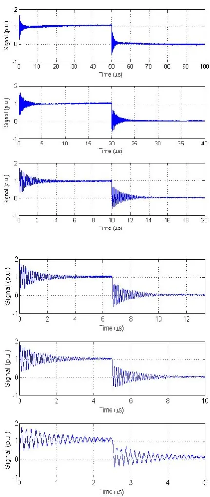
Fast switching times cause voltage reflections at the terminals of the twisted pair due to impedance mismatch. The shorter is the rise time, the shorter must be the cable to avoid this phenomenon [4]. Since the tests were carried out in a vacuum chamber (to test the influence of a partial vacuum), the inverter was connected to the specimen using a 5 meters long cable. Five meters are far above the theoretical limit for a rise time of 14 ns to avoid reflections, thus overshoots at voltage flanks were inevitable. By inspecting Fig. 1, one can conclude that the oscillations due to switching operations of the inverter are independent of the inverter switching frequencies.
The tests were performed at the following switching frequencies: 5 kHz, 10 kHz, 25 kHz, 50 kHz, 75 kHz, 100 kHz and 200 kHz. To measure the RPDIV, the DC-bus voltage was increased in steps of 10 V starting at a value high enough to avoid long test times, but lower than the expected RPDIV.
C. PD test system
[image:2.595.59.272.292.399.2]The rise time of the inverter is 14 ns, comparable with the time duration of a PD pulse [11]. This feature prevents electrical detection, at all test frequencies. Since the test were carried out within a vacuum chamber where light could not get in, PDs were coupled using a Photo-Multiplier Tube (PMT Module H5773-04 from Hamamatsu). To better distinguish signal from noise, the output of the PMT was processed by an envelope demodulator. The amplified signals were sent to an oscilloscope using a first-order high-pass filter.
Fig. 1 - Surge waveforms at the different commutation frequencies used for PD testing
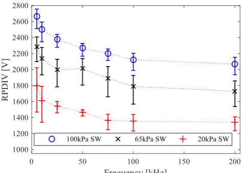
Fig. 2 - Behavior of RPDIV as a function of frequency and for different pressure levels
For each test condition, the RPDIV was measured on 10 different fresh samples. After each measurement, we replaced the twisted pair under test to prevent the influence of PD-induced degradation on experimental results.
III. RESULTSANDDISCUSSION
As mentioned before, in the experiments was possible to measure only the RPDIV, because of the constraints imposed by the test setup. By definition, the RPDIV is the voltage level at which PD events occur with probability 50% during an inverter surge. Thus, RPDIV is higher than the PDIV value.
Fig. 2 shows the peak-to-peak RPDIV B10 (10% probability percentile) and its 95% confidence intervals as a function of switching frequency and pressure. As expected, the RPDIV decreases with pressure. The RPDIV decreases with frequency, reaching a plateau when the switching frequency approaches 100 kHz. The saturation frequency is a mild function of the pressure: 100 kHz in the cases of 100 kPa and 65 kPa, close to 75 kHz at 20 kPa.
A. Influence of pressure
The dependence of PDIV (and, as a consequence, of the RPDIV) on the pressure has often been modeled using Paschen’s law [13]:
pd C K pd p E V
c
b
(2)
where p is the pressure, d is the distance between electrodes,
E/p
c is the specific critical electric field (which is the limit value for ionization to occur in the gas), C is a constant and K considers the electronic secondary emission from cathode, :
1 1/
log
[image:3.595.323.539.61.241.2]K (3)
Fig. 3 - Behavior of RPDIVn as a function of pressure
Based on the data (for air) coming from different labs, the constants in equation (2) simplifies to [14]:
pd pd
Vb 24.36 6.72 (4)
Indeed, the Paschen’s law is derived by observing discharges occurring in a gas region limited by metallic electrodes establishing a quasi-uniform field. The secondary electrons emitted by the cathode (-process) play a fundamental role in defining the breakdown voltage, which is affected by the electrodes (material, surface finish). Furthermore, the breakdown mode described by the Paschen’s law is when a (theoretically) infinite value of avalanches of small magnitude raise the current in the gap to infinity. On the contrary, PD incepted in a motor insulation occur in a non-uniform field bounded by insulated conductors, and a PD is a single avalanche.
To decide whether the Paschen’s law (eqn. (4)) could model RPDIV data, we had to evaluate the length of the discharge lines. This was done using Comsol Multiphysics using a simplified 2D model (infinitely-long cylindrical conductors). The voltage between the electrodes was set to the peak value of RPDIV. The length of the discharge lines, was determined searching for the lines satisfying the Schumann criterion:
70 / d 10
dx p E
(5)
where is the effective Townsend ionization coefficient, whose dependence on E/p was taken from [15]. The coefficient 7 was determined by comparing results from several samples having different geometries [16].
The plot of RPDIV as a function of pd (not reported here for the sake of brevity) shows that the collected data have behavior akin to that predicted by eqn. (3), but with an offset. Thus, we decided to introduce a correction factor to the above equation:
pd pd
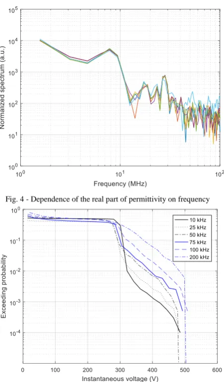
[image:3.595.48.287.62.231.2]Fig. 4 - Dependence of the real part of permittivity on frequency
Fig. 5 - Dependence of the real part of permittivity on frequency
Using the least squares, we evaluated =0.48. This constant is much lower than the reference value, 6.72, suggesting that is much higher than that of the electrodes used in eqn. (4). This conclusion indicates the existence of a significant memory effect above 10 kHz, which influences the inception of partial discharges and, therefore, RPDIV value.
Since the Paschen’s law is not apt to model RPDIV results, we introduced the following, empirical, quantity:
f RPDIV
f p RPDIV f
p
RPDIVn
, kPa 100
,
, (7)
Note that, contrarily to the Paschen’s law, it is not necessary to evaluate length of the discharge line to evaluate eqn. (7). Fig. 3 shows RPDIVn as a function of pressure highlighting an almost linear relationship between the two quantities. This finding should be substantiated by other, alternative, sources. However, if confirmed, it could help the design of the insulation of aircraft or EVs.
B. The influence of waveform characteristics
Observing Fig. 2, we can observe a dependence of RPDIV on the switching frequency. As mentioned, the RPDIV decreases for increasing frequency, until it reaches a “saturation” value around 75-100 kHz.
To explain this effect, we investigated the behavior of the relative permittivity of the insulation as a function of frequency as we thought that the highest frequency contributions due to ringing and overshoots could affect the value of permittivity. However, Table 1 shows that the permittivity variations are not large enough to justify any dependence of RPDIV on frequency.
We focused on the effects of the oscillations due to switching on RPDIV. By using the Short-Time Fourier Transform [17], we tested the instantaneous spectrum of the surge having the larges frequency content. From the results, reported in Fig. 4, it comes out that, during commutation, the frequency content of the voltage surges is independent of frequency.
Conversely, comparing the exceeding probabilities of the voltage absolute values (see Fig. 5), is possible to see that, with increasing frequencies, the probability distribution shifts to higher values. This result is due to the impact of ringings, that becomes more and more important (see Fig. 1). Thus, the larger the commutation frequency, the higher will be the average voltage even though the peak voltage (used to characterize the waveform) is the same. This increases the probability of incepting PD at a given voltage level and, thus, RPDIV can be detected at lower voltage levels when the voltage is ramped up during the tests.
IV. CONCLUSIONS
The measurements reported here show that the RPDIV depends linearly on pressure, a finding that could help insulation design. Different labs should test independently charts akin to that reported in Fig. 3, to verify if this empirical evidence is applicable or not to all types of insulation. To keep into account the reduction of breakdown strength of the air, we suggest testing aircraft actuators at voltage levels that are roughly 35% higher than those used for industrial actuators [7]. We have observed that surge ringings, besides posing a threat to insulation reliability, impact on the RPDIV measurement. Using surges with low repetition frequency (e.g., 10 kHz), one could get RPDIV values that are too large compared with the actual values experienced in service. leading to the dangerous situations when wide band-gap devices are used for e.g. aircraft.
REFERENCES
[1] J. A. Rosero, J. A. Ortega, E. Aldabas, L. Romeral, “Moving towards a more electrical aircraft,” IEEE Aerospace and Electronic Systems Mag., vol. 22, no. 3, pp. 3-9, 2007.
[2] E. Persson, "Transient effects in the application of PWM inverters to induction motors," IEEE Trans. Ind. Appl., vol. 28, pp. 1095-1101, 1992 [3] M. Kaufhold, G. Borner, M. Eberhardt and J. Speck, "Failure mechanism of the inter-turn insulation of low voltage electric machines fed by pulse-controlled inverters," in IEEE Electr. Insul. Mag., vol. 12, no. 5, pp. 9-16, Sept.-Oct. 1996.
[4] G. Pietrini, D. Barater, G. Franceschini, P. Mancinelli and A. Cavallini, “An open problem for More Electrical Aircraft (MEA): how insulation systems of actuators can be qualified?,” 2016 IEEE Energy Conversion Congress and Exposition (ECCE), Milwaukee, WI, USA, 2016, pp. 1-8.
[5] P. Mancinelli, S. Stagnitta, A. Cavallini, “Qualification of hairpin motors insulation for automotive applications,” IEEE Transactions on Industry Applications , vol. PP, no. 99, pp.1-1, 2016.
[6] G. C. Stone, S. Campbell, S. Tetreault, "Inverter-fed drives: Which motor stators are at risk?", IEEE Ind. Appl. Mag., vol. 6, pp. 17-22, 2000 [7] W. Yin, "Failure mechanism of winding insulation in inverter-fed
motors," IEEE Electr. Insul. Mag., vol. 13, no. 6, pp. 18-23, 1997. [8] J. C. G. Wheeler, “Effects of converter pulses on the electrical insulation
in low and medium voltage motors”, IEEE Electrical Insulation Magazine, vol. 21, no. 2, pp. 22-29, March-April 2005
[9] A N. Foulon, J. P. Lucas, G. Barré, R. Mailfert, J. Enon, "Investigation of the failure mechanism of insulation subjected to repetitive fast voltage surges," Proc. IEEE EIC/EMCW '97, pp. 401-406, 1997.
[10] D, Fabiani, A, Cavallini, G. C. Montanari, “Aging investigation of motor winding insulation subjected to PWM-supply through PD measurements,”, IEEE CEIDP ’05, pp. 434-437, 19-19 Oct. 2005. [11] P. Morshuis, “Assessment of dielectric degradation by ultrawide-band
PD detection,” IEEE Transactions on Dielectric and Electrical Insulation, vol. 2, no. 5, pp. 744-760, Oct 1995.
[12] IEC 60034-18-41 ed. 1, Rotating electrical machines – Part 18-41: partial discharge free electrical insulation systems (Type I) used in rotating electrical machines fed from voltage converters – Qualification and quality control tests, 2014.
[13] W. O. Schumann, “Über das Minimum der Durchbruchfeldstärke bei Kugelelektroden,” Archiv für Elektrotechnik, vol. 12, pp. 593-608, 1923.
[14] E. Kuffel, W. S. Zaengl, and J. Kuffel, “High voltage engineering – Fundamentals,” Oxford, U.K.: Newnes, 2000.
[15] Phelps Database from LXcat, http://www.lxcat.net/, Accessed: 2016-06- 13.
[16] L. Lusuardi, A. Cavallini, P. Mancinelli, G. M. De La Calle, J. M. Martinez-Tarifa, G. Robles, “Design criteria for inverter-fed Type 1 motors,” 2016 IEEE International Conference on Dielectrics (ICD), Montpellier, pp. 605-608, 2016.
[17] M. Portnoff, "Time-frequency representation of digital signals and systems based on short-time Fourier analysis," IEEE Trans. on Acoustics, Speech, and Signal Processing, vol. 28, no. 1, pp. 55-69, Feb 1980.