David
L.
Daniels
1Ian L
.
Williams
Victor M
.
Haughton
This article appears in the November / Decem-ber 1983 issue of AJNR and the January 1984 issue of AJR.
Received January 18, 1983; accepted after
revision June 24, 1983.
1 All authors: Department of Radiology, Medical
College of Wisconsin, 9200 W. Wisconsin Ave. Milwaukee, WI 53226. Address reprint requests to D. L. Daniels.
AJNR 4:1227-1232, Nov/Dec 1983 0195-6108/83/0406-1227 $00.00 © American Roentgen Ray Society
1
227
Jugular Foramen:
Anatomic and
Computed Tomographic Study
The computed tomographic (eT) appearance of the jugular foramen was examined in detail, and anatomic and CT sections were correlated. The pars nervosa and pars vascularis were identified, and, with intravenous contrast enhancement, a rapid se-quence of scans at a gantry angle of +30° to the canthomeatal line demonstrated cranial nerves IX, X, and XI. The osseous margins of the jugular foramen were best shown by CT at planes of sections parallel and positive (0°_30°) to the canthomeatal line. CT can be used to evaluate osseous anatomy and the jugular foramen with precision sufficient to confidently exclude an intracanalicular mass.
The
computed tomographic
(CT)
appearance of glomus
jugul
are
tumors
has
been described [1 -3], but
th
e
norm
a
l
co
nfigur
atio
n
of the
foramen
and it
s
contents has not yet been
co
mpletely analyzed by CT. W
e
undertook
a cor
r
e
l
ative
study with head and skull
s
pecimens and
c
lini
ca
l
s
ubje
cts
.
Materials, Subjects, and
Methods
In preliminary studies, we found that a plane of section 30° cephalad to the canthomeatal line (CML) just below the internal auditory canal, was nearly tangential to the endocranial opening of the jugular foramen (fig. 1). Dissecting fresh, frozen cadavers with a hand-held rotary grinder (Dremel Moto-tool), we identified cranial nerves IX, X, and XI in the jugular foramina (figs. 2-4). We also studied the appearance of the jugular foramen in a dry skull by removing bone in 1 mm increments with the rotary grinder (fig. 5).
To determine the CT appearance of the jugular foramen, we imaged a dry skull and some patients at several planes between -15° and +30° to the CML (figs. 6-8). We also reviewed the appearance of the jugular foramen in our conventional posterior fossa CT studies, done at - 15° with respect to the CML [5].
Four patients with symptoms of a jugular foramen lesion (pulsatile tinnitus, cranial nerves IX, X, and/or XI deficit, etc.) were placed supine in the GE CT /T 8800 scanner with their heads elevated about 30° on a foam pad. CT images were obtained at a plane +30° to the CML determined with the lateral localizer scan. On the basis of our anatomic dissections, this plane is perpendicular to the intraforaminal course of cranial nerves IX-XI. Five- and 1.5-mm-ttiick sections were obtained about 5 mm below the internal auditory canal to locate the jugular foramen. We injected 50 ml of 60% iodinated contrast agent manually and rapidly in an antecubital vein via an 18 gauge Angio-cath needle. CT images were obtained at a single level; the first scan was 5 sec after the initiation of the injection and then every 10-15 sec until four scans were obtained. Technical factors included 1.5 mm collimation, 120 kVp, 9.6 sec scan time, pulse width of 2 msec, and 356 or 409 mAs (figs. 9 and 10). Subsequently, 150 ml of 30% iodinated contrast agent was infused and contiguous CT scans were obtained through the region of interest.
Results and Discussion
122
8
DANIELS ET AL.
AJNR:4, Nov./Dec. 19831
2
~
IInf. Petrosal Sinus
~
,
in Petro-OccipitalSuture IX
~
, /
I
Transverse Sinus(
"
~----Jugular Spine
Jugular Vein
Fig. 1 .-Parasagittal analomic section. Plane of endocranial opening (arrow) of jugular foramen forms 30° angle with CML. Plane is just below internal auditory canal.
Fig. 2.-Skull base from above. Common sheath of cranial nerves X and XI in pars vascularis and cranial nerve IX in pars nervosa. (Adapted from [4].)
A
B
Fig. 3.-Sections through medulla of fresh, frozen cadaver viewed from above and posteriorly. A, Cranial nerves IX, X, and XI (bracket) extend to jugular
foramen. B, Dural septum (OS) separates meatus of IX and X-XI. SA = basilar artery.
a
nt
e
riorly
,
l
ate
r
a
lly,
a
nd
inferiorly
from
the
e
ndocr
a
nium
to
th
e exocra
nium
between the
tempor
a
l
a
nd
occipital bones.
The foramen is di
vid
ed into
two p
arts by a
fibrous
or osseous
bridg
e
that
co
nne
cts
th
e
jugul
a
r
spine on
the petrous part
of
the tempor
a
l bone
and
the jugular process
of
the occipital
[image:2.615.56.561.86.304.2] [image:2.615.55.559.387.604.2]AJNR:4, Nov./Dec. 1983
CT OF JUGULAR FORAMEN
1229
A
B
Fig. 4.-Jugular foramen after removal of dura covering jugular bulb (B). A, Cranial nerve IX has separate meatus. B, After removal of dura covering cranial nerve IX, cranial nerve X and cranial (C) and spinal (S) parts of cranial nerve XI are identified as they join in jugular foramen.
A
B
Fig. 5.-Endo-(A) and exo- (B) cranial openings of jugular foramen. Pars nervosa (N) and vascularis (V) are at endocranial opening. Wilh endocranial end
of canal removed, exocranial opening is identified. PO = petrooccipital fissure; lAC = internal audilory canal; HC = hypoglossal canal.
jugular bulb
and
the vagus (X)
and spinal accessory
(XI)
nerves
.
The pars vascularis is usually larger
on
the right
causing asymmetry of the jugular foramina.
Cranial nerves IX,
X, and XI
have
a constant position
in
the jugular foramen (fig
s.
2-4)
.
Cranial nerves
X
and
X
I
a
r
e
in a com
mon sheath near the anteromed
i
a
l wall
o
f the jugul
a
r
bulb
.
Ant
erior
to them
and separ
a
ted fr
o
m th
e
m by
a
dural
1230
DANIELS ET AL.
AJNR:4, Nov./Dec. 1983A
B
Fig. 5.-A, Normal pars nervosa (N) and vascularis (V) (left) and eroded jugular foramen (right) in patient with large glomus jugulare tumor (arrows). CT section is +300 to CML. B, Normal left hypoglossal canal (solid arrow) and jugular foramen in patient with metastatic breast carcinoma eroding right jugular foramen and hypoglossal canal (open arrows). CT section is +300
to CML.
A
B
Fig. 7.- A, M-shaped anterolaleral edge (arrow) of jugular foramen of dried skull embedded in paraffin. B, Smoother posteromedial edge (black arrow) in
section 5 mm caudad. Hypoglossal canals (white arrows) are medial to jugular foramina. Plane of section + 1 00 to CML.
nerv
e
IX.
The
inferior
petrosal sinus has
a
variable
course
from th
e
petrooccipital fissure
around cran
i
a
l
nerves IX,
X
a
nd
X
I to the
jugular bulb.
Th
e
pars vascularis and
nervos
a
together
are
seen
on
CT
at
planes parallel and
positive
(00-30
°
)
to the
CM L (figs
.
6
a
nd
7).In
this
rang
e
of gantry
a
ngulations
because of
the
oblique
c
ourse of
t
he jugular
foramen, sequential a
x
i
a
l
sec-tions demonstrate the anterolateral M-shaped edge of
the
endocranial
opening; then,
in
sections
2-5
mm more
cau-dad, the posteromedial straighter
edge
of the
endocranial
AJNR:4, Nov./Dec. 1983
C
T O
F
J
U
G
ULAR
FOR
A
M
E
N
1231
A
B
Fig. 8.-Pars vascularis (V) and jugular bulb (8) in CT sections - 150 to CML. A is from dried skull embedded in paraffin; B is a patient after infusion of
intravenous contrast agent.
A
B
c
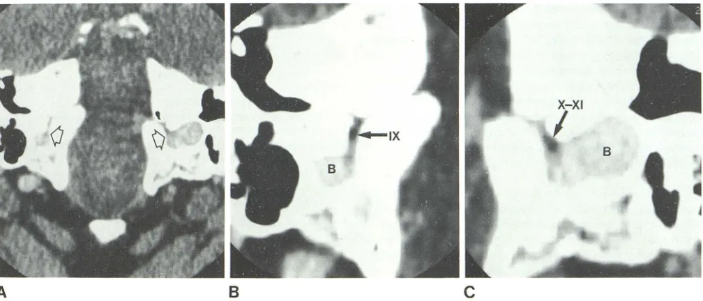
Fig. 9.- Jugular foramina (arrows) at plane of section +300 to CML with iugular bulb (8) maximally enhanced during rapid sequence of scanning (A). Cranial
nerve IX in pars nervosa and cranial nerves X-XI in pars vascularis are seen. Band C are higher magnification of right and lett foramina, respectively.
pa
r
s
v
asc
ul
a
ri
s is we
ll
v
i
sua
li
zed, b
u
t t
h
e pars ne
r
vosa
i
s not
(
fig
. 8).
Th
e
fill
i
n
g defec
t
s
in th
e enha
n
ced
j
u
gu
l
ar foramen on CT
im
ages correlate w
ith
c
r
an
i
a
l n
erves
IX, X,and
XIin
ana-t
o
mi
c dissect
i
o
n
s (figs
.
9 a
n
d 10). Cranial nerves
Xand
XIt
oget
h
e
r
ap
p
ear on axial C
T
as an oval-shaped defect near
the antero
m
ed
i
a
l
wa
ll
of the jugular bulb. Cranial n
erve
IX [image:5.612.55.557.90.312.2] [image:5.612.57.561.380.596.2]1232
DANIELS ET AL.
AJNR:4, Nov./Dec. 1983A
B
and
IX was
seen in
two of four patients. These nerves were
not well visualized in images
obtained
5-30
min
after
infu-sion of contrast
medium
.
To
evaluate
the
osseous anatomy
of the jugular foramen
a
nd
exclude osteolytic changes,
we recommend using
a
gantry angle
parallel
or
positive to the CML. To visu
a
lize
cranial
nerves IX
,
X, and XI and
the jugular bulb
or
sus-pected intr
aca
n
a
licular masses,
a
gantry angle
30°
positive
to
the
CML,
a
bolus injection
of contrast agent, and a
rapid
sequence of scans
a
re
suggested.
From this limited
study
of clinical subjects,
we believe the
structures
within the
jugul
ar
foramen
can be identified
with
enough
precision to
co
nfidently
excl
ude
an
intracanalicular mass.
REFERENCES
1. Mancuso AA, Hanafee WN. Computed tomography of the head
Fig. 1 D.-Sequential scans of jugular foramen
obtained at rapid rate and after intravenous
con-trast medium injection. As jugular bulb (6) en
-hances, cranial nerves tX and X-XI are seen an -terior to bulb.
and neck. Baltimore: Williams & Wilkins, 1982
2. Caughran M, White T J III, Gerald B, Gardner G. Computed
tomography of jugulotympanic paragangliomas. J Comput
As-sist Tomogr 1980;4 : 1 94-1 98
3. Marsman JWP. Tumors of the glomus jugulare complex (che
-modectomas) demonstrated by cranial computed tomography.
J Comput Assist Tomogr 1979;3: 795-799
4. Strickler JM. New and simple techniques for demonstration of
the jugular foramen. AJR 1966;97: 601-606
5. Daniels DL, Williams AL, Haughton VM. CT of the medulla.
Radiology 1982; 145: 63-69
6. Gray H. Anatomy of the human body. Philadelphia: Lea &
Febiger, 1966
7. Rhoton AL, Buza RC. Microsurgical anatomy of the jugular
foramen. In: Rand RW, ed. Microneurosurgery, 2d ed. SI.
Louis: Mosby, 1978:252-264
8. Di Chiro G, Fisher RL, Nelson KB. The jugular foramen. J