Performance Analysis of PV Solar Power System
Neha Ahire Amit Agrawal Dugra Sharma Department of EEE Department of EEE Department of EEE Dr. C.V. Raman University Dr. C.V. Raman University Dr. C.V. Raman University
Abstract- In this paper I have extended my previous work. Previously I have done performance analysis of PV Solar Power System with the help of PV SYST Software, in which 10kWp grid-connected PV Solar Power System is simulated. The energy supplied to the grid and the main performance analysis is done by considering the effect of different global irradiation and temperature, the annual performance ratio is also considered, with normalized production and loss factor.
Now I have analyzed Power Quality parameter in which I take harmonic because harmonic content in a supply have significant effect on power system. THD in output voltage of 10kWp grid connected PV Solar Power System is measured by using Harmonic Analyzer 5850.
Finally found the harmonic on system on addition of 50kWp PV Solar Power System which university is planning to install in order to reduce the cost of electricity and effect on harmonics by boosting reactive power in a system by using ETAP simulation software.
The harmonic level increases on addition of 50kWp PV Solar Power System, but remain within acceptable limit as per IEEE guideline standard.
Index Terms- Harmonic Analyzer 5850, harmonics, THD, PV Solar Power System.
1) INTRODUCTION
Today when there is crisis for fossil fuel on earth solar energy emerged as boon for our increasing power demand. PV Solar power system is a best way for conversion of solar energy in to electricity and today due to reduction in PV panel prices it is affordable. And roof top PV Solar Power System even solve our issue of land area. Thus, best utilization of suns free energy.
Now when it comes to electrical output of a system, the measure concern is power quality, however, it is actually the quality of the voltage that is being addressed. The power supply system can only control the quality of the voltage; it has no control over the currents that particular loads might draw.
Therefore, the standards in the power quality area are devoted to maintaining the supply voltage within certain limits.
AC power systems are designed to operate at a sinusoidal voltage of a given frequency [typically 50 hertz in India] and magnitude. Any significant deviation in the waveform magnitude, frequency, or purity is a potential power quality problem.
One of which is harmonics simply say distortion of the waveform. Distortion is any deviation from the normal sine wave for an ac quantity.
Harmonics are sinusoidal voltages or currents having frequencies that are integer multiples of the frequency at which the supply system is designed to operate. Harmonic distortion is caused by nonlinear devices in the power system. Nonlinear load is Electrical load that draws current discontinuously or whose impedance varies throughout the cycle of the input ac voltage waveform.
Harmonic distortion levels are described by the complete harmonic spectrum with magnitudes and phase angles of each individual harmonic component. It is also common to use a single quantity, the total harmonic distortion (THD).
The THD is a measure of the effective value of the harmonic components of a distorted waveform. [1]
This index can be calculated for either voltage or current by:
THD =
ℎ 𝑚𝑎𝑥ℎ >1 𝑀ℎ2
𝑀1
where Mh is the rms value of harmonic component h of the quantity M.
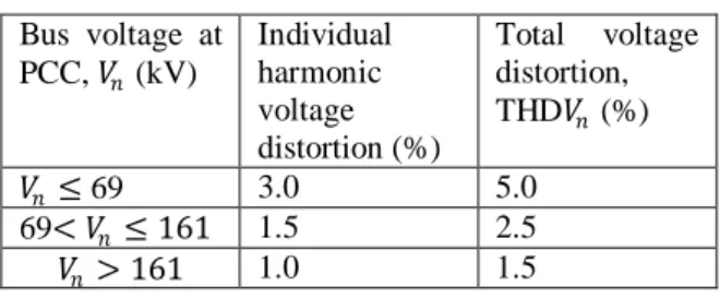
IEEE Standard 519-1992 provides guidelines for acceptable levels of voltage distortion on the utility system. These are summarized in Table I [2]
Table I Harmonic Voltage Distortion Limits in Percent of Nominal Fundamental Frequency Voltage
Bus voltage at PCC, 𝑉𝑛 (kV)
Individual harmonic voltage distortion (%)
Total voltage distortion, THD𝑉𝑛 (%)
𝑉𝑛 ≤ 69 3.0 5.0
69< 𝑉𝑛 ≤ 161 1.5 2.5
𝑉𝑛 > 161 1.0 1.5
2) MATHODOLOGY
I. THD Analysis of 10k𝑊𝑝 grid connected PV Solar Power System by Harmonic Analyzer 5850.
Harmonic Analysis of 10k𝑊𝑝 Grid connected PV Solar Power System is done by using Harmonic Analyzer 5850 which is installed in C. V. Raman university campus.
The control Panel i.e. inverter section is shown in fig. 1
Fig1: Inverter section
Voltage and current probe are inserted at ACDB the output of inverter feeding to grid.
The THD of 𝑉1= 0.32%, 𝑉2= 0.34%, and 𝑉3= 0.32%.
II. THD Analysis of PV connected distribution system by ETAP software
Single line diagram of PV connected distribution system of Dr. C.V. Raman University is shown in figure3. At present distribution system is supplied from 315kVA, 11000/415V Grid connected Transformer, 10k𝑊𝑝 solar panel is also grid connected through 415 V system at Bus 5. [3]
Total harmonic distortion found from software simulation of one line diagram of PV connected distribution system of Dr. C.V. Raman University is THD at bus3, bus4, and bus5 is 0.31%, 0.28%
and 0.27% respectively. It is within acceptable limit as per guideline of IEEE Standard 519-1992.
Fig2: Harmonic Analyzer connection .
. Fig3: one line diagram of PV connected distribution system of Dr. C.V. Raman University
Fig.4 THD analysis of 10k𝑊𝑝 Grid connected PV solar system
III. THD Analysis on addition of 50k𝑊𝑝 PV Solar system.
Dr. C.V. Raman University is planning to install 50k𝑊𝑝 PV Solar Power System to reduce its cost of energy on bus4 of its existing distribution system.
Harmonic level due to addition 50k𝑊𝑝 PV Solar Power system is also simulated by ETAP Software.
Total harmonic distortion (THD) on addition of 50kW Solar Power system is 1.20%, 1.40% and 1.40%.Which is also within acceptable limit as per IEEE guideline.
IV. THD Analysis on boosting reactive power To study the effect on Total Harmonic Distortion (THD) on boosting the reactive power, three phase capacitor bank of different kvar rating is inserted at Bus4. As shown in figure6.
THD at different capacitor bank rating is given in table II.
Fig.5 THD Analysis with additional 50k𝑊𝑝 PV Solar system. Table II. THD at different capacitor bank rating
Capacitor Bank Rating (kvar)
THD% at Bus4 THD % at Bus5
0.04 1.40 1.40
0.08 1.40 1.41
0.1 1.40 1.41
0.4 1.40 1.41
0.8 1.40 1.42
1 1.42 1.42
Fig.6 THD Analysis with capacitor at Bus4
3) RESULT AND DISCUSSION
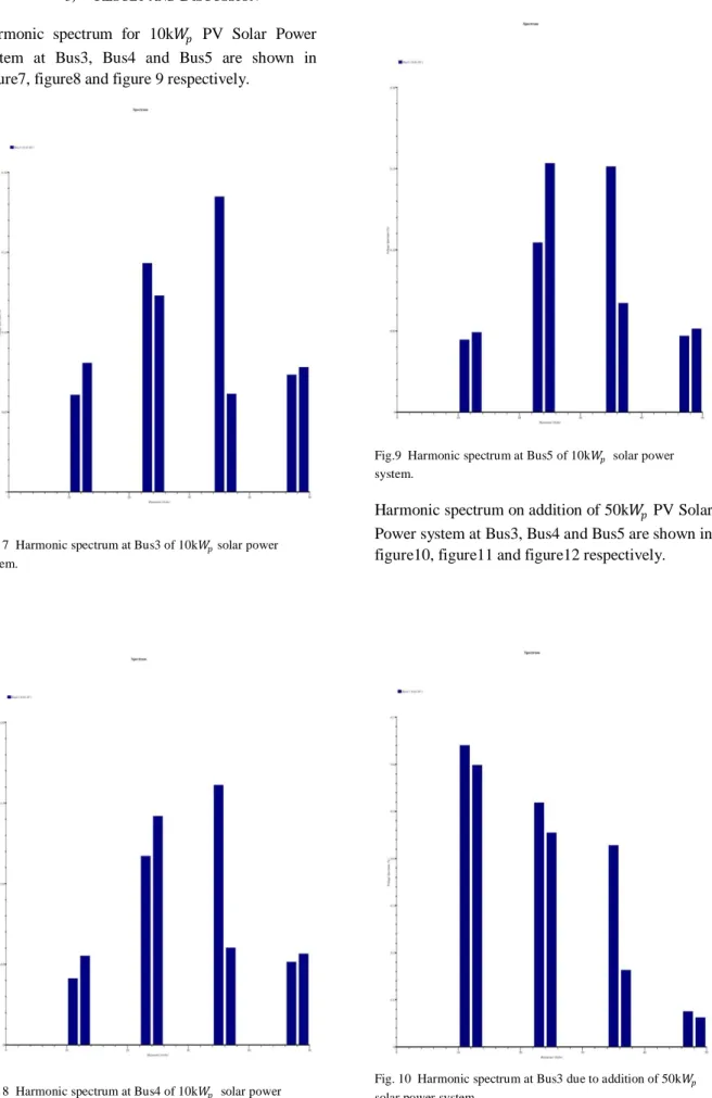
Harmonic spectrum for 10k𝑊𝑝 PV Solar Power system at Bus3, Bus4 and Bus5 are shown in figure7, figure8 and figure 9 respectively.
Fig. 7 Harmonic spectrum at Bus3 of 10k𝑊𝑝 solar power system.
Fig. 8 Harmonic spectrum at Bus4 of 10k𝑊𝑝 solar power system.
Fig.9 Harmonic spectrum at Bus5 of 10k𝑊𝑝 solar power system.
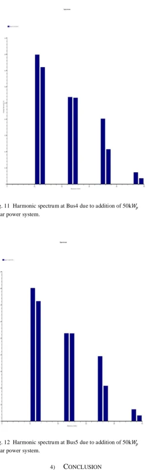
Harmonic spectrum on addition of 50k𝑊𝑝 PV Solar Power system at Bus3, Bus4 and Bus5 are shown in figure10, figure11 and figure12 respectively.
Fig. 10 Harmonic spectrum at Bus3 due to addition of 50k𝑊𝑝 solar power system.
Fig. 11 Harmonic spectrum at Bus4 due to addition of 50k𝑊𝑝 solar power system.
Fig. 12 Harmonic spectrum at Bus5 due to addition of 50k𝑊𝑝 solar power system.
4) CONCLUSION
In this paper Total harmonic distortion of 10k𝑊𝑝 PV Solar Power System is measured by Harmonic
Analyzer and same is simulated by ETAP Software. The value of THD measured by Harmonic Analyzer is 0.32%. and software simulation give 0.27%. There is slight difference between two measurement this can be because of output of PV Solar system is different at particular hour.
On addition of 50k𝑊𝑝 Solar Power System it is found that the harmonic level is increased but remains within acceptable limit as per IEEE standard guideline. THD at Bus5 is 1.40%.
Now on inserting capacitor bank of 0.04kvar at Bus4 it is found that there is no change in THD level. But on increasing the reactive power input THD level increases.
ACKNOWLEDGMENT
The authors gratefully acknowledge the contribution of everyone involved during the planning and organizing the background for this project.
REFERENCES
[1]. Roger C. Dugan, Mark F. McGranhan, Surya Santoso, H.
Wayne Beaty, Electrical Power Systems Quality, McGraw-Hill.
[2]. IEEE Standard 519-1992, table 11.1.
[3]. Mr. Amit Agrawal, Dr .Dharmendra Kumar Singh “Harmonic Impactof Grid Connected Photovoltaic system on Low Voltage Power system” 3rd International Conference for Convergence in Technology (12CT), 978-1-5386-4273.