Design and Analysis of a Novel Multi-Input Multi-Output High Voltage DC Transformer Model
By
Mais Alzgool
A thesis submitted in partial fulfilment of the requirements of the University of the West of England, Bristol for the degree of Doctor of Philosophy
Faculty of Environment and Technology, Department of Engineering Design and Mathematics, University of the West of England, Bristol September 2018
Thesis Advisory Committee
DOS. Dr. Hassan Nouri
I ABSTRACT
A novel Multi-Input Multi-Output (MIMO) step-up DC transformer for applications in high voltage renewable energy sources is designed and presented. This design topology can provide a high step-up conversion gain without using an internal AC transformer, to supply different DC output voltage levels from integration of various input power sources. MIMO DC transformers provide flexibility in terms of choice and availability of the power source, reduction in the number of power lines used to transfer power to pre-specified locations as well as enhancement in system reliability. The comprehensive operating principle, theoretical analysis and design criteria of the proposed MIMO step-up DC transformer have been discussed. The proposed DC transformer has the advantages of simple configuration, fewer components, high conversion gain and high efficiency. The relations between the inputs and outputs are expressed mathematically in terms of passive components and the duty cycle of power switches. Also discussed is the sizing of the employed inductors and the capacitors for a particular application. The derived input and output expressions for ideal and non-ideal DC transformer are solved numerically and the results are validated against those obtained through MATLAB-SIMULINK simulation. Tentative analysis of the numerical and simulation results shows a close correlation.
The Proportional Integral Derivative (PID) controllers have been used to control and operate the proposed MIMO step-up DC transformer in Continuous Conduction Mode (CCM) utilising the concept of closed loop Voltage Mode Control (VMC). As the behaviour of the proposed MIMO DC transformer resembles a nonlinear plant performance, hence Small Signal Modelling (SSM) and linearization of the plant are required to obtain a linear model for ease of analysis and to achieve a more stable and regulated output voltages.To obtain the SSM of the plant to be controlled, the mathematical modelling and the state space representation in a matrix form of the proposed MIMO DC transformer have been derived within the DC transformer’s switching states. This yields the transfer function presentation of the designed DC transformer which have been used to determine the system’s stability.
II
and open circuit faults across the diodes. Furthermore, a comparative performance and cost analysis has been carried out between the proposed MIMO and two selected published DC transformers. The selection criteria is discussed in details. The main parameters used for analysis are size, weight, voltage conversion gain, duty cycle and efficiency. Also considered are the cost of utilised semiconductors and passive components.
III Dedication
IV
Acknowledgments
First, praises and thanks to the God, the Almighty, for his blessings throughout my studies. I would like to acknowledge all the invaluable help from my supervisor, Dr. Hassan Nouri, without whom this work would not have been possible. This dissertation comes from numerous discussions with him, from his keen insight and guidance in a productive research area. I want to thank him for consistently encouraging me no matter under what kind of situations.
I also want to thank Dr. Chris Toomer, for her help and guidance during my study at UWE, no matter in the researches, the stages of my dissertation work or other aspects. And also to show her my great appreciation for her great support.
I owe more than thanks to my family members for their support throughout my studies; I would like to thank my father Dr. Bassam Alzghoul, my mother Heyam Alawneh, as well as I would like to thank my father and mother in law for their encouragement. Without them I would not have reached this point.
A special thanks to my husband, Ghaith, for his encouragement, patience and endless support over the years. Thank you for helping me and for being by my side all the time.
V
List of Publications
(1) Alzgool, M. Alzghoul, G. Nouri, H. and Toomer, C. (2016). A Novel Multi-Inputs-Single-Output DC Transformer Topology. Coimbra: 51st International Power Engineering Conference, ISEC Portugal. “Cited by 2”.
(2) Alzgool, M. and Nouri, H. (2017). Design, Control and Modelling of a Novel Multi-Input Multi-Output Boost Converter Hub. Amman: the 10th Jordan International Electrical and Electronics Engineering Conference (JIEEEC).
VI
Table of Contents
Abstract ... i
Dedication ... iii
Acknowledgments ... iv
List of Publications ... v
Table of Contents ... vi
Glossary ... X Chapter 1. Introduction and Research Objectives ... 1
1.1. High Voltage Direct Current (HVDC) Transmission Technology ... 1
1.1.1 Reasons for HVDC ... 1
1.1.2 Background to offshore Wind farms and (the Role of) why MIMO DC Transformers ... 3
1.2. Research Objectives... 7
1.3. Research Methods ... 8
1.4. Summary of Contributions ... 9
1.5. Thesis Outline ... 10
Chapter 2. Literature Review ... 12
2.1. Multi-Input Multi-Output DC Transformers for High Voltage DC Networks .... 12
2.1.1. Review of existing DC transformers topologies ... 12
2.1.1.1. Single-Input Single-Output step-up DC Transformers ... 16
2.1.1.2. Multi-Input Multi-Output step-up DC Transformers ... 18
2.1.2. Isolated and non-isolated step-up DC transformer topologies ... 23
2.2. DC transformers Control Methods ... 27
2.2.1. Voltage mode control method ... 28
2.2.2. Current mode control method ... 29
2.2.3. Linear (classical) control technique ... 31
2.2.4. Non-linear (intelligent) control technique ... 33
2.2.4.1. Fuzzy logic control technique ... 33
VII
2.3. Summary ... 35
Chapter 3. DC Transformer Theory ... 37
3.1. Conventional DC transformer topologies ... 37
3.1.1. Boost converter ... 38
3.1.1.1. Continuous conduction operation mode ... 39
3.1.1.2. Discontinuous conduction operation mode ... 41
3.1.2. Buck converter ... 45
3.1.2.1. Continuous conduction operation mode ... 47
3.1.3. Buck-Boost converter ... 49
3.1.3.1. Continuous conduction operation mode ... 49
3.2. Semiconductor switching devices ... 51
3.3. Small signal analysis ... 55
3.3.1. State space averaging approach ... 56
3.3.1.1. Ideal DC-DC boost converter transfer function ... 59
3.3.1.2. Non-ideal DC-DC boost converter transfer function ... 62
3.4. Switching controller considerations ... 64
3.5. Summary ... 66
Chapter 4. The Proposed MIMO Step-up DC Transformer Design ... 68
4.1. A Multi-string series connected step-up DC transformer topology ... 68
4.2. Operation of MIMO DC transformer in continuous conduction mode ... 71
4.2.1. Mathematical derivation of the proposed MIMO DC transformer in continuous conduction mode ... 78
4.2.1.1. Ideal MIMO step-up DC transformer ... 78
4.2.1.2. Non-ideal MIMO step-up DC transformer ... 79
4.3. The proposed MIMO DC transformer specifications ... 82
4.3.1. Passive components sizing ... 82
4.3.2. Power losses and efficiency of the proposed MIMO DC transformer .. 92
4.3.3. The optimal operating frequency of the proposed MIMO DC transformer ... 97
4.4. The DC characteristics of the proposed MIMO DC transformer ... 105
4.5. Summary ... 114
VIII
5.1. Introduction... 116
5.2. The proposed MIMO DC transformer structure and operation principles ... 117
5.3. Dynamic modelling of the proposed MIMO DC transformer ... 125
5.3.1. Linearization of MIMO DC transformer using state space averaging approach ... 126
5.3.2. MIMO DC transformer transfer functions ... 132
5.3.3. PID controllers tuning method ... 138
5.4. Stability analysis of the designed MIMO DC transformer ... 142
5.4.1. Dependency of stability on PID gain selection ... 143
5.5. Study into flexibility and robustness of the designed PID controller ... 162
5.5.1. First scenario: All input sources are available in the system to feed the loads ... 164
5.5.1.1. Fixed demand and supply ... 164
5.5.1.2. Demand and supply variation ... 166
5.5.2. Second scenario: One of the input power sources fails to supply the loads ... 169
5.5.2.1. Low pass filter design ... 172
5.5.3. Third scenario: system performance under fault conditions ... 176
5.5.3.1.Short Circuit (SC) fault across the transistors ... 178
5.5.3.1.1. SC transistor with solid fault (RF=0) on the input side of the proposed DC transformer ... 179
5.5.3.1.2. SC transistor with solid fault (RF=0) on the output side of the proposed DC transformer ... 182
5.5.3.1.3. SC transistor with non-solid fault (RF>0) on the input side of the proposed DC transformer ... 183
5.5.3.1.4. SC transistor with non-solid fault (RF>0) on the output side of the proposed DC transformer ... 185
5.5.3.2. Open Circuit (OC) fault across the diodes ... 192
5.6.Summary ... 198
Chapter 6. Evaluation of the Designed MIMO DC Transformer... 201
6.1. Evaluation and comparison of existing published MIMO DC transformers ... 201
6.2. Evaluation and comparison of the proposed MIMO DC transformer with the selected published DC transformers ... 207
IX
6.2.2. Manufacturing cost of the proposed topology and the selected published
topologies ... 222
6.3. summary ... 225
Chapter 7. Conclusions and Recommendations ... 228
7.1. Conclusions ... 228
7.2. Recommendations and further work ... 232
References ... 233
Appendices ... 245
Appendix A ... 246
Appendix B ... 249
Appendix C ... 274
Appendix D ... 276
X Glossary
AC Alternating Current DC Direct Current
MIMO Multi-Input Multi-Output SISO Single-Input Single-Output MISO Multi-Input Single-Output DISO Double-Input Single-Output HVDC High Voltage Direct Current
FACTS Flexible Alternating Current Transmission System MOSFET Metal–Oxide Semiconductor Field Effect Transistor FET Field Effect Transistor
IGBT Insulated Gate Bipolar Transistor GTO Gate Turn OFF Thyristor
ZVS Zero Voltage Switching FLC Fuzzy Logic Control P Proportional Controller
PI Proportional Integral Controller
PID Proportional Integral Derivative Controller M Conversion Ratio
D Duty Cycle of power Switch DCM Discontinuous Conduction Mode PWM Pulse Width Modulation
MIC Multi-Input Converter
CCM Continuous Conduction Mode CMC Current Mode Control
VMC Voltage Mode Control kd Derivative gain
ki Integral gain
kp Proportional gain
XI
SSM Small Signal Model
Z-N Ziegler-Nichols tuning method MATLAB Matrix Laboratory
PFM Pulse Frequency Modulation SCR Silicon Controlled Rectifiers BJT Bipolar Junction Transistor
SEPIC Single-Ended Primary Inductance Converter PV Photovoltaic
WVR Wind Voltage Regulator D/A Digital /Analogue converter A/D Analogue/ Digital converter
1
CHAPTER ONE
INTRODUCTION AND RESEARCH OBJECTIVES
1.1. High Voltage Direct Current (HVDC) Transmission Technology 1.1.1. Reasons for HVDC
2
Figure 1.1 losses in AC and DC transmission technology with the transmission distance- Image Credit ABB [6]
A HVDC transmission line costs less than an AC line for the same transmission capacity. However, it is also true that HVDC terminal stations are more expensive because of the fact that they must perform the conversion from AC to DC, and DC to AC. But over a certain critical distance (approximately 600 − 800 𝑘𝑚) the HVDC alternative will always provide the lowest cost [6] as shown in figure 1.2.
[image:14.595.166.494.498.720.2]3
It could be summarised that the HVDC technology becomes more desirable for the following reasons as listed in [7]:
1. Environmental advantages where HVDC systems have a lower environmental impact because they require fewer overhead lines to deliver the same amount of power as HVAC systems. And HVDC is a key component in the future energy system based on renewable energy sources such as wind and solar power which are remotely located.
2. Economic advantages where HVDC is the cheapest solution compared with the conventional HVAC transmission over long distances because the construction costs of DC lines are cheaper than for AC lines, in spite of the extra cost of a converter station.
3. Asynchronous (Non-synchronous) interconnections with HVDC technology. Asynchronous interconnection between adjacent power systems.
4. Fast control of power flow, which implies stability improvements, not only for the HVDC link but also for the surrounding AC system.
5. Direction of power flow could be changed quickly (bi-directionality) for storage elements applications.
6. No limits in transmitted distance. This is valid for both overhead lines and sea or underground cables.
7. Reinforcing of an AC network which is heavily loaded.
8. The elimination of AC collector system at the remote generating stations can result in better efficiency in the operation of turbines which are free to run at speeds independent of the system frequency.
The aforementioned reasons led researchers to focus on HVDC technology and its applications.
1.1.2. Background to offshore Wind farms and (the Role of) why MIMO DC Transformers
4
that there will be 40 𝐺𝑊 of installed offshore capacity by 2020, rising to 150 𝐺𝑊 by 2030 [9]. In the USA, about 85% of the gross offshore wind resource (4000 𝐺𝑊) occurs in areas of transitional depths (30 − 60 𝑚) or deep-water areas (> 60 𝑚) located up to more than 90 𝑘𝑚 from the shore [10]. To integrate such a large amount of remote offshore energy generation into the existing onshore networks creates a number of technical, economic and environmental challenges for the developers and system operators [12]-[14].
In general, offshore wind strength is greater than onshore strengths and many large-scale wind farms (greater than 1𝐺𝑊) are constructed in offshore locations. Offshore generated power is normally transmitted over long distances. In the future, proposed wind farms at distances of over 60 𝑘𝑚 from the shore will be connected to the mainland grid only through DC links [2]. As stated in section 1.1.1 DC can transport relatively more power at the same voltage/insulation level than AC. Therefore, HVDC transmission is considered an effective way of connecting offshore wind farms to the main grid. The European super-grid is proposed to interconnect the existing HVDC lines in the North and Baltic seas and to provide transmission access for offshore wind farms [15]. Many large HVDC links experience limitations on power levels and the sending and receiving ends of the DC networks have difficulties in accommodating the number of injections or distributions of high powers at a single point. The HVDC limitations are driving the demand for Input and Multi-Output (MIMO) DC transformers or DC sub-stations by highlighting the significant incentive of a technology that can provide additional access points (input and output). Figure 1.3 highlights the general structure of offshore wind farm HVDC technology with and without MIMO DC transformers, where MIMO DC transformers provide an integration of 𝑚 number of wind farms to supply 𝑛 number of loads in different locations through submarine DC cables with various voltage levels.
5 Of fshor e wind Of fshor e wind Of fs h o re o r Is lan d VSC s tatio n On sh o re VSC s ta tio n Of fs h o re MI MO DC s u b stat io n Of fs h o re o r is lan d v o lt ag e so u rce co n v er ter s tatio n AC Gr id On sh o re VSC s ta tio n On sh o re VSC s ta tio n 𝑊 𝑖𝑛 𝑑 𝑓𝑎𝑟𝑚 1 𝑊 𝑖𝑛 𝑑 𝑓 𝑎 𝑟𝑚 𝑚 DC ca b le DC ca ble 𝑛 DC ca ble 1 DC ca ble 1 DC ca ble 𝑚 DC ca b le AC ca b le AC ca b le AC Gr id 1 AC Gr id 𝑛 (a ) U se d HV DC Te chnol og y (b) P ropose d HV DC Te chnolog
y with M
IMO D C T ra ns for mer Of fs h o re MI MO DC s u b statio n On sh o re v o ltag e so u rce co n v er ter s tatio n On sh o re v o lta g e s o u rce co n v er ter statio n Of fs h o re w in d p o w er p lan t AC Gr id Of fs h o re o r is lan d v o ltag e so u rce co n v er ter s tatio n
Figure 1.3general structure of wind farms (a) used HVDC technology [18] and (b) the proposed HVDC
6
Furthermore, a suitable megawatt DC transformer would enable tapping of HVDC lines and hence the development of multi-terminal HVDCs which are favourable conditions for submarine DC transmission, which requires DC voltage stepping at megawatt power levels. A high-power DC transformer would also aid the development of Flexible AC Transmission System (FACTS) technology by enabling connection to a wide range of DC sources.
Also the proposed MIMO DC transformer will be useful for onshore wind farms where the energy supply infrastructure will face severe shortages in the future and will require integration and increased diversity of energy sources, such as photovoltaic cells, fuel cells, and batteries as shown in figure 1.4 which will have different voltage and current characteristics. This increase in the type and the rating of these sources suggests their direct connection to medium or high voltage DC grids at the MIMO collecting point is desirable [16]. Also remote rural communities, which are in relative proximity of DC lines would significantly benefit from accessing the power supply through tapping into the DC grid [17].
Figure 1.4 the block diagram of MIMO DC transformer technology with different renewable and
non-renewable energy sources- Image Credit © Canva [170]
The interfacing of multiple sources to DC collecting points will provide improved reliability and flexibility. Nowadays, such DC collecting points are known as Multi- Input (MI) DC
Multi-Input
Multi-Output
Step-up
DC
Transfor
mer
AC/DC
𝑚 Input source
DC-Load
AC-Load
7
Converters, having the capability of diversifying different energy sources. To date, most direct DC-DC conversion is based on Single-Input Single-Output (SISO) basic topologies. As most electrical storage and load levelling devices in power systems use a DC type storage media (battery, super capacitor, capacitors, superconducting magnetic energy storage, etc) with widely varying DC voltage levels, their integration into the power grid has, until recently, been difficult.
1.2. Research Objectives
The purpose of this PhD research is to design a Multi-Input Multi-Output (MIMO) step-up DC transformer topology with the advantages of simple configuration, fewer components, and high efficiency compared with the available published topologies. The new topology will encompass high efficiency, high reliability and simple control. The project needs to be developed to a point where a detailed description of the proposed MIMO step-up DC transformer topology, operation principles, theoretical analysis, design criteria and its control strategy are provided. Various strategies for controlling and co-ordinating the source and load sides of the DC transformer, based on closed-loop DC voltage control characteristics, need to be investigated to provide adequate DC voltage regulation and power sharing among the connected sources and loads from the concept of power management control through a dedicated, flexible control algorithm.
The robustness of the designed controller needs to be tested under different scenarios of faults, dynamic change in power demand or supply, and in the availability of the input sources.
The detailed digital simulation of the proposed design on a MATLAB-SIMULINK platform needs to confirm satisfactory operating principles under various scenarios. This will ensure verification of the feasibility of the proposed scheme where a MIMO step-up DC transformer will be highly controllable and flexible since it will be based on power electronics.
The main aims of this project are:
1. The development of optimal topology for high-ratio MIMO DC Transformers or DC substations.
2. The development of a switching algorithm; highly efficient, simple and reliable. 3. The development of reliable and efficient power management control.
4. The development of local control for each terminal of the MIMO DC transformer. 5. The development of a master control for DC voltage regulation within the overall
8
1.3. Research Methods
A scientific approach [8] has been used to obtain the aims of this project as shown in figure 1.5. At the beginning of this research work, the relevant subject information was collected using the available sources, including published papers and books. Familiarisation with MATLAB software took place concurrently with the literature survey. Attention has been given to project topology design principles, switching, control algorithms and the process of analysis for the results obtained through simulation with those derived numerically.
For attaining the aims, the project was then divided into two parts. The first part consists of designing a MIMO step-up DC transformer topology for renewable energy sources for medium to high voltage applications, and derivation of the mathematical expressions which describe the output with the input and duty ratio for an ideal and non-ideal DC transformer. This part of the work is presented in chapter four of the thesis.
9
Figure 1.5 the proposed research methodology
1.4. Summary of Contributions
1) A review of the related published papers on DC Transformers and the gathering of the related essential data.
2) The design of a novel Multi-input and Multi-output (MIMO) step-up DC Transformer using insulated gate bipolar transistors in view of an efficient topology in terms of producing a high step-up conversion gain without using an internal AC transformer, reduced switching losses, response of switching speed and minimum use of components.
3) The proposed design is flexible and costly effective. Having a DC hub collection point which is easy to monitor, assemble and effective to distribute the energy. 4) Derive generic expression which consider the Mathematical description of the
10
5) Generating mathematically from first principles efficient and robust switching signals for cases when demand changes and sources are fixed, or sources are fixed and demand changes or both demand and the source change. Voltage mode control is used to regulate the output DC voltage.
6) The Construction of the proposed Multi-input and Multi-output step-up DC transformer with its related control algorithm within dedicated software.
7) The Simulation of the constructed MIMO step-up DC transformer in various scenarios for validity of its robustness, efficiency, flexibility and reliability. 8) The evaluation of the proposed MIMO step-up DC transformer whereby
comparative analysis has been performed with selected published topologies.
1.5. Thesis Outline
The thesis is structured in seven chapters:
Chapter one presents the motivation of this work and the importance of HVDC technology over HVAC and the role of offshore wind farms in HVDC technology. It also shows the main aims and research objectives with their corresponding methodologies. The research contributions to knowledge have been summarised in this chapter. Finally, it shows the organisation of this thesis.
Chapter two presents a comprehensive literature survey which has been carried out to provide an insight into the design of a novel MIMO step-up DC transformer for high voltage offshore wind farms technology. It also reviews the available control methods and techniques used for regulation of the DC voltage of the DC transformers.
Chapter three discusses the theoretical background of conventional DC transformers which also is known as DC-DC converter topologies. It also presents the operational principles of the basic topologies in continuous and discontinuous conduction modes with their associated mathematical expressions. This chapter shows the reasons for utilising the IGBTs as semiconductor power switches in the proposed design. It also presents the control operation method where Pulse Width Modulation (PWM) has been used in the proposed controller design.
11
step-up DC transformer are discussed. Furthermore, for the proposed DC transformer, the optimal operating frequency of utilised power switches is presented. Finally, the main characteristics of the proposed design and the software simulations in steady state condition without a controller are described and presented in this chapter.
Chapter five describes modelling and control algorithms of the proposed MIMO step-up DC transformer. Also shown are the proposed control technique where Proportional Integral Derivative (PID) controllers have been integrated to control the proposed design. The mathematical modelling of the controller design is presented in this chapter and the stability analysis of the proposed MIMO DC transformer is performed through a transfer function approach. Results show the validity of the proposed DC transformer’s control performance which is demonstrated through MATLAB-SIMULINK software simulation under different scenarios depending on the utilisation of the input sources. Furthermore, the design of a low pass filter is presented for improvement of the output voltage response curve and also to protect the design from the high voltage spikes which it acquires under specific conditions. Finally, the performance of the proposed MIMO step-up DC transformer under open circuit (across the diodes) and short circuit (across the switches) faults is examined in this chapter and the simulation results are presented.
In chapter six a number of the most recently published MIMO step-up DC transformer topologies with high voltage conversion gain are reviewed. Based on the conversion gain and the boosting techniques used, two different topologies have been selected in order to evaluate the proposed design. Also, the comparative analysis and the performance characteristics of the proposed and the selected topologies under predefined specifications are shown. Finally, the manufacturing cost of the passive components and the semiconductors which used in the proposed and the pre-selected designs are compared and presented in this chapter.
12
CHAPTER TWO
LITERATURE REVIEW
In this chapter, A comprehensive literature survey will be carried out in order to provide an insight into the design of a novel Multi-Input Multi-output (MIMO) step-up DC transformer for high voltage offshore wind farm technology. Also, a review of the existing DC transformer topologies will be provided and summarised in this chapter to show the novelty of the proposed design.
2.1. MIMO DC Transformers for High Voltage DC Networks 2.1.1. Review of existing DC transformers topologies
DC transformers (or DC-DC converters) have been extensively utilised at low power levels and a number of topologies exist. However, most of these technologies are not suitable for scaling up to megawatt power levels. The limitations are linked to the nature of the switches at the highest power, the operating frequencies, efficiency, switch utilisation, and others. Conventional, unidirectional step-up DC transformers [20] cannot achieve gains larger than (2– 4) because of difficulties with the output diode. There have been attempts to develop DC transformers with internal AC transformers [20]-[21] at higher power levels; however, some serious inherent limitations, in terms of stepping ratios and power levels have been demonstrated [22]. Another limitation is with the type of switch, for example, DC transformers utilise Metal–Oxide Semiconductor Field-Effect Transistors (MOSFETs) as switches with around a 10 𝑘𝐻𝑧 frequency, which gives low prospects for further increasing to megawatt power levels.
There has been significant research worldwide to develop megawatt sized SISO DC transformers using Insulated Gate Bipolar Transistors (IGBTs), and very promising topologies include a full-bridge converter with a medium frequency AC transformer and resonant topologies [23]. Recent research [24] noted that the Multi-Terminal (MT) DC substation is considerably more complex than two-terminal units and that there is need for more research on design optimisation.
13
Recently, there has been activity in the design of various topologies with the Multi-Input DC-DC converter with the possibility of Multi-Output (MO) DC transformers for applications such as grid-connected integrated hybrid generation systems, fuel cells, micro-grid-based telecom power systems, uninterruptible power supplies, and electric and hybrid electric vehicles.
The operation modes of a two-input single-output DC-DC step-up converter for small-size wind-photovoltaic generation are analytically studied in terms of voltage ripples for each operation mode in [29]. The converter topology consists of two step-up DC-DC choppers connected in series and tested via computer simulation. A prototype implementation and testing were later presented in [30] by the authors.
In [31] a MISO DC-DC converter for hybrid vehicles is presented and a prototype developed. The converter consists of three step-down /step-up (buck/boost) converters connected in parallel. The inputs of the converter are a fuel cell generator, a battery and an ultra-capacitor. In the same year the construction of a bi-directional DC/DC converter, mainly consisting of an unsymmetrical half-bridge converter, was reported [25]. In this design a transformer provides the galvanic insulation between the low voltage and the high voltage side. The operating principle and the power transfer characteristics are determined analytically and used to design a 1.6 𝑘𝑊 prototype.
The MI DC-DC converter topology with minimal parts reported by [27] allows only a unidirectional power flow, which has a negative output voltage.
In [26] two MISO DC-DC transformer topologies are proposed: a buck-boost and a forward type, both with coupled inductors (multi-winding transformer) between the inputs and the output. The buck-boost is studied in detail for a two-input configuration with one input from a solar panel and one from an AC line. The equivalent circuit is constructed for different operation modes and the corresponding transfer function of the converter determined. Theoretical results are confirmed by experiment.
14
In [35] three new MI DC-DC converter topologies are proposed, and a comparative study conducted between ten different topologies taking into consideration flexibility, reliability and modularity potential for ideal component implementation.As a result of the comparative study it could be found that the multi-input boost buck-boost is the only topology which integrates different inputs, also it could obtain relatively high flexibility.
A bi-directional multi-input one-output DC-DC transformer/converter is presented in [36]. The converter has only one inductor connected to all the inputs. It can operate in boost, buck or buck-boost mode. In boost mode it can have only one input connected. In reverse operation it can charge only one input from the output side. The work focuses on the operation of the MI buck topology. In Discontinuous Conduction Mode (DCM) only one input switch can conduct at a time. Differential equations for the output voltages are determined for different operation scenarios.
The research presented in [33] uses the concept of the zero-volt switching multi-input bidirectional DC-DC converter with a multi-winding transformer as a link between the input and output. When in reversed mode this converter can work with only one input. The concept of the multi-winding transformer is presented in detail with a mathematical description of DC-DC converter operation modes. Simulated current and voltage waveforms are presented for each operating mode, as well as an analysis of the output power from each input source according to the DC-DC converter control variables.
Reference [37] is a short paper explaining the generation of MI converters from their respective SI versions. Based on several assumptions, restrictions, and conditions, the analysis indicates that MI development is feasible. The study uses four rules to identify SI topologies that can be extended into multiple-input circuits. In the same year a duty cycle duration was evaluated for a Single-Ended Primary Inductance Converter (SEPIC) type of MI DC-DC convertor dedicated for Photovoltaic (PV) modules considering the same triggering time. Where a new SEPIC topology is proposed with two coupled inductors (transformer) to obtain the Maximum Power Point (MPP) on each input cell. The duty cycle of one input cell is dependent on the duty cycle of all the other inputs which limits the duty cycle of each input.
15
isolated loading por. The different operation modes of the converter are analysed and presented in detail. The control system of the converter consists of three feedback controllers: a Solar Voltage Regulator (SVR), a Wind Voltage Regulator (WVR) and global Output Voltage Regulator (OVR). For the proper design of SVR, WVR and OVR a dynamic model in the case of a small signal perturbation is developed.
A comprehensive study of two bidirectional DC-DC converter topologies presented in [40] for tapping into HVDC from a medium AC voltage level without AC transformers. The proposed topologies are single-input single-output which can work with line commutated converters or voltage source converters used on the AC/DC side. Basic PI control systems are used for the presented topologies. Possible control limitations are analysed and PSCAD simulations are made for tapping into the 1000 𝑀𝑊 HVDC CIGRE benchmark network.
(T. Preti, et al) have designed a high gain DC transformer with a coupling inductor, designed to boost low voltages to voltages into a high range of 30 to 50 times Input voltage with the help of a PI controller [41]. To achieve high voltage output gain, the converter output terminal and boost output terminal are connected in series with the isolated inductor with less voltage stress on the controlled power switch and power diodes.
A proposed MI step-up DC transformer which draws power from several input sources has been simulated in [42]. This Multi-Input Converter (MIC) can deliver power from all the input sources to the load, either individually or simultaneously. The MIC reduces the system size and cost by reducing the number of components. Three different operation modes are discussed, and a PI controller is used for the closed loop performance of the MIC.
A MISO isolated three-level DC transformer presented in [43] with a transformer links the output of the system to the input sources. The architecture eliminates two boost switches which are present in the two-stage counterpart. A low voltage prototype has been designed to serve as a proof of a concept.
16
switches and consequently reduces the converter efficiency [48]. In [49] an MI high step-up boost converter has been presented which has been made up of 𝑛 conventional boost converters which increases the voltage gain by 𝑛 times.
The study in [50] has achieved a high voltage gain with continuous input current and a simple control circuit. But large switch voltage stress becomes one concern. The study in [51] and [52] proposes an effective topology that can achieve high voltage gains without high duty-cycle by cascading several voltage multiplier cells, whereas the high output voltage is achieved through lifting capacitor voltage step by step. This leads to a high voltage stress of the capacitors which increase the size and cost of the DC transformers.
It is obvious that a step-up DC transformer is one of the most interesting designs for applications of boosting and regulating the low and variable output voltage of renewable energy for the DC link of grid connected systems [44]– [46]. Therefore, in the following sections a review of the existing step-up DC transformer topologies has been summarised and tabulated based on the operating power level, stepping gain and the number of inputs and outputs. In addition, the most recently published high gain non-isolated step-up DC transformer topologies have been reviewed and summarised in chapter six of this thesis.
2.1.1.1.Single-Input Single-Output step-up DC transformers
17
Table 2.1 review of the existing published SISO Step-up DC transformer topologies
Reference number of Presented Topology Title Y ea r Number of inputs and outputs Relation between the input and the output voltage
Switching
algorithm Applications
[53] Design high gain DC-DC boost converter with coupling inductor. 2014 Single-input Single-output
The relation is not included Only one switch switching with specific duty ratio Low voltage applications (fuel, solar energy system) [54] A high voltage ratio and low stress DC/DC converter with reduced input current ripple for fuel cell source 2014 Single-input Single-output
𝑉𝑜 = 2 1 − 𝐷𝑉𝑖
The switch and the diode switched simultaneo usly High voltage transfer gain (renewable energy systems, fuel cell) [55] High voltage gain interleaved DC boost converter application for photovoltai c generation system 2012 Single-input Single-output
𝑉𝑜 = 1 + 𝐷 1 − 𝐷𝑉𝑖
Only one switch operating by controlling the switching period photovoltaic generation system [56] Hybrid switched inductor converters for high step-up conversion 2014 Single-input Single-output
𝑉𝑜 =
1 + 2𝐷 1 − 𝐷 𝑉𝑖
18 [57] A novel high step-up DC/DC converter based on integration coupled inductors and switched-capacitors techniques for renewable energy application s 2015 Single-input Single-output
𝑉𝑜 =
2 + 𝑛 + 𝑛𝐷
1 − 𝐷 𝑉𝑖
Where 𝑛 is the transformer’s turn ratio Only one switch operating by controlling the switching period for the switch and the diodes Renewable energy sources [58] Experiment al evaluation of soft- switching DC/DC converter for fuel cell
vehicle application s 2002 Single-input Single-output
𝑉𝑜 = 𝑛 1 − 𝐷𝑉𝑖
Where
𝑛 =𝑁𝑠 𝑁𝑝 For one input there are four switches. And every two switches switching simultaneo usly Fuel cell powered electric vehicle [59]
Design of a non-inverting synchronou s Buck-Boost DC/DC power convert with moderate power level 2009 Single-input Single-output
𝑉𝑜 = 𝐷 1 − 𝐷𝑉𝑖
Q1,Q3
works as a group and
Q2,Q4
works as another
group
Solar system applications
2.1.1.2.Multi-Input Multi-Output step-up DC transformers MI [42], [29], [34], [33], [65], [66], [36] and [60] and MO [62]-[64], [67], [27] and [68] step-up DC transformer topologies have been presented with different numbers of passive components and semiconductors. And again, some of these topologies used an internal AC transformer in order to have a high conversion gain. For different number of inputs and outputs, the number of power switches have been used to increase the voltage level by adjusting the switches’ duty cycle value.
19
as well as the size and the weight of the DC transformer. Also, the internal AC transformer makes the design bulky and costly.
While in [62] a SIMO step-up DC transformer topology has been presented which is suitable for low and high voltage applications, the drawback of this design is that the power switches operate sequentially which means they cannot be active at the same time and thus the power is delivered just one load at a time.
In [63] a MIMO step-up DC transformer for electric vehicle applications has been presented. For 𝑚 inputs and 𝑛 outputs there are (𝑚 + 𝑛 + 2) power switches used, and this increases the size, weight and cost as well as the losses of the system. Furthermore, in this design the inputs are connected in parallel, thus the input power switches can operate simultaneously if all input sources are identical. Otherwise only one input at a time could be connected to the system.
20
Table 2.2 review of the existing published MIMO Step-up DC transformer topologies
Presented
Topology Title
Y ea r Number of inputs and outputs
Relation between the input and the output
voltage
Switching
algorithm Applications
[60] A multiple -input DC/DC converter for renewable energy system 2005 Multiple - input Single-output
𝑉𝑜= 𝑛 1 − 𝐷𝑉𝑖
Where
𝑛 =𝑁𝑠 𝑁𝑝 For tow inputs there are four switches operated simultaneou sly High voltage applications [42] Modelling of multi-input DC/DC converter for renewable energy sources 2014 Double-input Single-output with storage element
𝑉𝑜=
1
1 − 𝐷(𝑉1+ 𝑉2)
Boosting switches operated simultaneou sly and sequentially with the storage element switches Renewable energy sources (wind, solar) [29] Testing of a new DC/DC converter topology for integrated wind-photovolta ic generating system 1993 Double-input Single-output
The relation is not included Two switches operated simultaneou sly Photovoltaic-wind generating system [34] New DC/DC converter for energy storage system interfacing in fuel cell
hybrid electric vehicles 2007 Double-input Single- output
𝑉𝑜= 1
1 − 𝐷1
𝑉1 + ⋯
= 1
1 − 𝐷2
𝑉2 + ⋯
= 1
(𝐷1+ 𝐷2) − 1 𝑉3
Three switches cannot be active at the
same time
Fuel cell vehicles
[33]
A ZVS bi-directional DC/DC converter for multiple energy storage elements 2005 Double-input Single-output with storage element
21 [62] Multi- output DC/DC converters based on diode- clamped converters configurati on: topology and control strategy 2008 Single-input Multi-output
The relation is not included The switches operated sequentially then deliver the power to just one load
at a time
Low and high-power applications [63] A Non-isolated multi-input multi-output DC/DC boost converter for electric vehicle application s 2014 Multi-input Multi-output
The relation is not included The switches operated simultaneou sly Electric vehicle [64] Multi-output buck-boost converter with enhanced dynamic response to load and
input voltage changes 2010 Single-input Multi-output
The relation is not included
For 𝑛
outputs 𝑛 + 1 switches operated simultaneou
sly
Multi voltage DC networks or
multi-level inverters [65] Design of multiple- input power converter for hybrid vehicles 2005 Multi-input Single-output
The relation is not included
For 𝑛 inputs the 𝑛
22
[66]
Characteri stics of the
multiple- input DC/DC converter 1993 Multi-input Single-output
𝑉𝑜 = ( 𝑉1𝑡𝑂𝑁1
𝑁1𝑡𝑂𝐹𝐹 +
𝑉2𝑡𝑂𝑁2
𝑁2𝑡𝑂𝐹𝐹) /(1 +
𝑟𝑇𝑠2 𝑅𝑡𝑂𝐹𝐹)
For 𝑛 inputs the 𝑛
switches operated in complement ary way, then one input source will be connected at a time Renewable energy sources [67] A single-inductor multiple output switcher with simultaneo us buck, boost and inverted output 2011 Single-input Triple-output and can be extende d to generate
𝑛 −outp uts
The relation is not included
For 𝑛
outputs there are
(𝑛 + 1) switches
operated individually.
When the input switch is ON all the
other switches are OFF once the input switch OFF then the output switches will be ON sequentially
LED back light LCD monitor [68] A new DC/DC converter with multi output topology and control strategies 2008 Single-input Multi-output
𝑉𝑜=(𝐷𝑅 ∑𝑛𝑗=𝐾𝐷𝑗) /
(∑ [𝑅(∑𝑛𝑗=𝐾𝐷𝑗)
2 ] 𝑛 𝐾=1 ) The switches operated simultaneou sly with limitations on some switching states To supply multi-level inverters [27] A multiple- input DC/DC converter topology 2003 Multiple - input Single -output and Multiple - input Multiple - output could be construc ted)
For Two inputs
If 𝐷1> 𝐷2
𝑉𝑜= 𝐷1 1 − 𝐷1
𝑉1
If 𝐷2> 𝐷1 𝑉𝑜= 𝐷1𝑉1+ ( 𝐷2− 𝐷1)
1 − 𝐷2
23
[36]
A multiple-
input DC/DC converter
topology
2008 Multi-input
Single-output
𝑉𝑜= 1 1 − 𝐷1
𝑉1
For Boost: possible only with one input voltage at a
time
Hybrid electric vehicles
2.1.2. Isolated and non-isolated step-up DC transformer topologies
DC transformer topologies, as illustrated before, can be categorized as MISO [60], [33], [34], [36], [69]– [71], SIMO [72]– [76], or MIMO [63], [77]– [88] configurations. Under each category, two general configurations can be found in the literature: isolated (inputs and outputs are coupling magnetically) and non-isolated (inputs and outputs are coupling electrically) topologies. In fully isolated configurations, all ports of the DC transformer are isolated through a multi-winding transformer as noted in such MISO [58], SIMO [63], and MIMO topologies [77]– [79]. For applications that do not require isolation, non-isolated configurations can be both less costly and complex by providing a transformer-less solution as noted in such MISO [36], [71], SIMO [73]– [75], and MIMO [77], [81]– [86] topologies.
The MIMO topologies proposed in [77], [82]– [84], and [85] utilize one inductive element to transfer energy between sources and loads. While the use of one inductor results in lower magnetic volume and weight, it comes at a cost of pulsating input and output currents as source and load multiplexing are required (i.e., time sharing of the single inductor) [89]. This results in lower component utilization and increased source and load filtering requirements. In addition, due to their unidirectional structure, these topologies are not suitable for energy storage applications.
24
of these DC transformers, several switches are applied which leads to an increase of cost and losses. In addition, extending the isolated topologies to MIMO configuration by adding additional windings or internal AC transformers in an isolated SISO DC transformer such as in [93]-[96] will increase size and weight of the design, also the regulation is poor such that load variation of one output affects other output voltages.
In [97], an isolated multi-port bidirectional DC transformer has been presented. Using an AC transformer in this structure results in the limited switching for high frequencies, high losses, complicated structures, high size, and high costs. The two-input full bridge boost DC-DC converter presented in [98] benefits from a multi-winding transformer with different type of windings in primary and secondary sides. Other features of this structure are low input current ripple, separate controllers for each one of the inputs, and the possibility of expanding it to 𝑛 inputs. Nevertheless, by increasing the inputs, the number of the AC transformer windings, the complexity of these winding arrays, the number of switches and input inductors also increase [99]. Therefore, non-isolated high step-up DC transformers are employed to achieve high efficiency and low cost.
25
Figure 2.1 comparison between the isolated and non-isolated MIMO DC transformer designs as reported in [100]
Because of the drawbacks of isolated MIMO DC transformers as shown in figure 2.1, usage of non-isolated MIMO DC transformers seems to be more useful [90]. In [81], a MI DC transformer with just one inductor is proposed which can distribute load power between input sources. Also, transferring power between sources is possible.
A non-isolated step-up DC transformer topology with high step-up voltage gain is modelled in [101], so the voltage stress and current stress on the power switches can be reduced; however, the voltage conversion ratio is usually lower than 5. In [102], a triple input structure for hybridization of battery, photovoltaic cells, and fuel cell is introduced by the author. By proper switching of the converter the charge and discharge of the battery by means of other sources and load is possible, respectively. In [62] and [103], a single inductor MI DC transformer is proposed which can generate several different voltage levels in its outputs. The design is controlled to regulate the output voltages at their desired values
Features of MIMO
DC Transformers
Coupling
Magnetically
Pros
Isolation (safety) between the Input
and the Output and Noise
blocking
Sources Utilisation
Soft Switching
High conversion gain as it is a function of the transformer’s turns ratio
Cons
Difficulties of Designing multiple winding Transformer Increasing the circuit Volume (higher cost andhigher maintenance expenses) Frequency synchronisation is needed which complicate the control design
Extra output rectifier is needed
Coupling
Electrically
Pros
Sources Utilisation Soft SwitchingLess size (less number of elements) Less manufacturing and maintenance costs Possibility for high conversion gain without using internal ac
transformer
Cons
No isolation (no protection) between the input
and the output
26
despite the load power variation or input voltage variation. But by this design only one output can be provided. For the applications which require more than one output from several input sources there is one way to solve this problem which is by using MIMO DC transformers. In [104] and [105], a non-isolated MIMO DC transformer is introduced which has just one inductor. Using of large number of switches is a drawback of this design which caused low efficiency. Also, the impossibility of energy transferring between input sources is another disadvantage of the proposed design. In [86], a non-isolated MIMO topology capable of DC– DC and DC–AC conversion is proposed, although this topology is limited to only one load port and one energy storage port.
In [62] a MO step-up DC transformer has been presented, where its outputs are connected in series, and are used in high power and low power applications. In this structure for 𝑛 outputs, 𝑛 + 1 switches are needed, and also the controller system is complicated where a voltage control with hysteresis current control loop is used. In [76], a SIMO DC transformer with high efficiency and bidirectional power flow capability is presented. This structure has the ability of performing in both step-down and step-up modes. Complexity and big size are the main drawbacks of this design. In [84] a single stage MIMO DC transformer has been presented. This structure uses many switches, in which for 𝑛 input and 𝑚 output topology, 𝑛 + 𝑚 switches are utilised, which makes the structure very complex. In this structure by increasing the number of the input energy sources and output loads, the share of each energy source for supplying the output loads decreases. In [106] a MIMO DC transformer has been presented which is suitable for micro grid applications. In this structure by increasing the output loads, the input voltage sources also increase as well as inductors and switches. In addition, for 𝑛 input 𝑚 output mode, there are 𝑚2 of switches, 𝑚 inductors and 𝑚 DC voltage sources. According to this a high count of parts, high losses, big size, heavy weight, and more complicated structure have been obtained by this design.
27
2.2. DC Transformers Control Methods
DC transformers convert electrical energy from one level of voltage and current to another using power switching components. The input of the DC transformer is an unregulated DC voltage which produces a regulated output voltage having a magnitude that differs from the DC input voltage by changing the duty cycle of the power switches. Thus, due to the nature of power switches, the DC transformers are nonlinear systems which represent a big challenge for control design [29]. Fixed frequency Pulse Width Modulation (PWM) is the most used closed loop method to control switching power supplies and is used to design a controller with a high degree of dynamic response which is required in nonlinear systems [30].
A DC transformer is a voltage regulator so; in such applications, it must provide a fixed DC output voltage under input and load variations. There is much previous research which focuses on DC transformers and its associated control design. Due to the nonlinearity of the DC transformers; when designing a closed loop with classical (linear) control methods, a linearization of the plant is required. The mathematical representation of the plant to be controlled could be represented in a dynamic model of the switching DC transformer in order to obtain a Small Signal Model (SSM) [55].
When a DC transformer is employed in open loop mode, it exhibits poor voltage regulation and unsatisfactory dynamic response, and hence, this DC transformer is provided with closed loop control for output voltage regulation. Various closed loop control systems have been proposed such as a Proportional Integral Derivative (PID) controller as a linear control method, fuzzy logic and sliding mode control and other methods, as well as many other researchers presenting a new designs to be controlled with appropriate control technique such as [31] using soft switching technique, and [96] a method for high frequency power switches design using a fixed frequency switching strategy.
28
In controlling the DC transformers, a Voltage Mode Control (VMC) or Current Mode Control (CMC) are the most popular principles for regulating the output voltage. VMC and CMC could be applied simply by closing the feedback loop between the required output voltages and switching device duty ratio signal [27]. The VMC and CMC will be analysed in sections 2.2.1 and 2.2.2 respectively.
2.2.1. Voltage Mode Control Method
In the voltage regulation method there is only a single voltage feedback loop as shown in figure 2.2. In this method the output of the DC transformer is measured and compared with a reference voltage and then the differential compared value is used to produce a PWM signal to control the DC transformer’s power switch duty cycle 𝑑 . The duty cycle value will control the average voltage across the inductor in the DC transformer thus the output voltage will remain constant without any variation. In addition, this method is used to control the DC transformer topology in two modes Continuous Conduction Mode (CCM) and Discontinuous Conduction Mode (DCM). As in [40] the voltage feedback control method has been used to produce a constant output voltage. And a microcontroller is used to produce a set of PWM signals. The controller adapts as the input voltage varies whilst it requires additional effort to take variations of the load into consideration.
29
Figure 2.2 voltage mode control of DC transformer [107]
The disadvantage of using the VMC method in regulating DC transformers is that it provides a slower transient response [108]. When any changes occur in the input voltage or on the load side, this will be denoted as output voltage changes which will be sensed and then corrected by the feedback loop. In such applications it exhibits poor reliability and stability of the power switch [107].
2.2.2. Current Mode Control Method
In this method as shown in figure 2.3 there are two control loops: voltage and current control loops, so the CMC method is more complex than the VMC method as the additional loop in the CMC method is used to control the inductor’s current and then regulate the output voltage indirectly [32]. After sensing the inductor’s current, it will be compared to the control signal which is the difference between the output and reference voltage. By comparing the inductor’s current with the control signal the duty cycle 𝑑 of a particular frequency will be generated to derive the switch of the DC transformer.
There are several current mode control strategies which have been proposed in the literature [42]. Since instantaneous changes in the input voltage are immediately reflected in the inductor current, there are various current sensing techniques available in literature as CMC provides an excellent line transient response and the sensed current is used to determine when to switch between CCM and DCM thus, improving the efficiency of the power DC transformers in specific applications [41]. In the same paper [41] the author reviewed six
DC Transformer
𝑣
𝑖𝑣
𝑜𝑑
𝑉
𝑟𝑒𝑓Compensator
+
-𝑣
𝑒𝑟𝑟𝑜𝑟+
-Q
R
S
Clock
30
current sensing techniques used in current mode control and all those techniques need extra components for sensing the inductor current, for example adding sensing resistance in series with the inductor. This incurs power losses in the DC transformer and therefore reduces the DC transformer’s efficiency.
Figure 2.3current mode control of DC transformer [107]
The advantage of using the CMC method is that the transient response will be improved with a good performance in line regulation. And the main switch gains more protection by limiting the inductor’s current [107]. While it is a very unstable control loop when the duty cycle value exceeded 50% therefore it is not appropriate for control of the step-up DC transformers where the duty cycle value should be more than 50%. Also having two control loops will make the circuit more complicated and more difficult to analyse. Since the control modulation is based on a signal derived from the output current, oscillations in the power stage can insert noise into the control loop [108] which will be another drawback of CMC method. Furthermore, due to the nonlinearity of the CMC dynamics the SSM is difficult to achieve, also the additional inner feedback loop and the extra components and sensors which are needed in the CMC method will make the CMC method more complex to implement than the VMC method as well as costlier.
Therefore, research has been done where the DC transformers have been controlled by linear VMC methods and these controllers offer advantages such as fixed switching frequencies, zero steady state error and give a better small signal performance [38]. Consequently, the
DC Transformer
𝑣
𝑖𝑣
𝑜𝑑
𝑉
𝑟𝑒𝑓Compensator
+
-𝑣
𝑒𝑟𝑟𝑜𝑟+
-𝑖
𝐿(t)
Q
R
S
31
linear classical controller will be discussed in detail in this thesis as this technique has already been successfully used to control the proposed MIMO step-up DC transformer.
2.2.3. Linear (Classical) Control Technique
PID control is one of the oldest and most popular control techniques used for DC transformers [109], [110]. As shown in figure 2.4 the schematic diagram of the PID controller, there are different families P, PI, PD and PID could be used in controlling the DC transformers. These different combinations will give various ways to regulate the DC power supply in DC transformers.
Figure 2.4 block diagram of a PID controller in a feedback loop
The PID control signal is formulated as follows:
𝑚(𝑡) = 𝐾𝑝 𝑒(𝑡) + 𝐾𝑖 ∫ 𝑒(𝜏)𝑑𝜏 + 𝐾𝑑 𝑑𝑒(𝑡)
𝑑𝑡 𝑡
0 (2.1)
Where 𝑚(𝑡) is the control variable and 𝑒(𝑡) is the error signal over time.
A PID controller calculates an error value as the difference between the measured and the desired reference value [24], [34]. So, the PID controller must adjust three parameters 𝐾𝑝, 𝐾𝑖 and 𝐾𝑑 of the system which would affect the transient response, rise time, settling time, steady state error, overshoot and stability. Thus, it is not necessary for the system to adjust the three actions P, I and D and it may use only one or two actions to improve the system dynamic response. Here, 𝐾𝑝 is a gain adjustment acting on error signal and the integral gain 𝐾𝑖 adjusts the accuracy of the plant, while 𝐾𝑑 adjusts the damping of the plant [21]. Thus, before using a PID controller, the mathematical modelling of the plant to be controlled must be created, in contrast to intelligent (non-linear) control systems which do not need this mathematical model.
Measured value
+
-
+
+
+
Referencevalue
𝑒(𝑡)
𝐾𝑝𝑒(𝑡)
𝐾𝑖 ∫ 𝑒(𝜏)𝑑𝜏 𝑡
0
𝐾𝑑 𝑑𝑒(𝑡) 𝑑𝑡
𝑚(𝑡)
Plant / Process
P
I
32
A PID controller design procedure should include the mathematical modelling of the plant as well as the way of finding the PID parameters (𝐾𝑝,𝐾𝑖, 𝐾𝑑) which is called as PID tuning. PID parameters tuning is a core part of the controller design [47]. Many PID tuning methods had been derived to determine the value of the three parameters to obtain a controller with good performance and robustness [47] such as manual tuning method and Ziegler-Nichols (Z-N) method and these methods require retuning the parameters by trial and error to improve the controller performance. There are more advanced tuning methods to improve the performance and these need more computational processing and more information of the plant dynamics [115].
The choice of the tuning method should be based on the characteristics of the plant and performance requirement [47]. As a result, a method which is easy to use with simple formulae is always in demand if the desired performance is obtained [48]. The methods of trial and error, and Z-N have had a strong impact on the practice of control due to the simplicity in tuning the PID for designers as well as for the users with good performance and robustness [49], [107].
The PID controller is a popular control feedback used in industry due to its flexibility and easy implementation in real applications [23]. Furthermore, if the system is complex, the PID can be designed to track an error and assume the system as a black box. PID controller design requires a mathematical modelling of the plant which means that the output voltage derivative is replaced with information about the capacitor current thus reducing noise injection [35]. In [36] the performance comparison of the controller designed for DC transformer is made in terms of peak overshoot, rise time and robustness to load /input variations and it can be concluded that the PID controller obtained 0.009% overshoot peak while, 13.78% was obtained with a fuzzy logic controller, and the response of Z-N PID controller for input/load variation has a good performance proving that PID adapts through this research.
33
controller with step-up DC transformer, Z-N method and loop shaping method. And from the comparison results a conclusion can be made that the loop shaping method gives a better response than the Z-N method for the proposed model.
Although several MI DC transformer topologies have been presented for renewable energy system applications, only a few papers have mentioned the control techniques to control those DC transformers in different operating conditions [113]. Furthermore, the control strategy of the MI step-up DC transformer is presented to regulate the output voltage at the desired level. The PI controllers for the voltage and current loops have been designed for this case. PID controllers are useful for MI configurations such as in [33] where the concept of the Zero Voltage Switching (ZVS) MI bidirectional DC transformer with a multi-winding transformer is used as a link between the input and output. The firing pulse generation logic and PI control of the DC transformer are also presented.
2.2.4. Non-linear (Intelligent) Control Technique
In an intelligent control approach, it is not necessary to extract the internal dynamics of the plant to be controlled as the intelligent control system models the plant. An intelligent control system approach is enough in cases where the plant is too complex to be modelled [21].
The distinction between classical and intelligent control techniques is that an intelligent control method is used for a system that does not have to be mathematically modelled. Thus, different methods such as sliding mode control, fuzzy logic control [25], artificial neural networks [26], genetic programming [27] and others have been proposed in intelligent control as solutions to different control problems due to the complexity of the plant to be controlled.
In general, the intelligent control methods depend on learning the input-output behaviour of the plant to be controlled, for example fuzzy logic control is based on the idea that the human reasoning is approximate, non-quantitative, and non-binary [21]. Fuzzy logic control and sliding mode control as non-linear control techniques have been used in research to control the DC transformers. These two techniques will be discussed in sections 2.2.4.1 and 2.2.4.2 respectively.
2.2.4.1.Fuzzy Logic Control Technique
34
and its outputs as variables. Secondly, for each variable, there is a subset interval. For example, the velocity has three subset intervals: low, medium and high. Third, choose the shape of the membership functions between the various subsets as to whether they are changing linearly or not. After that the rules determine how the combinations of the inputs obtain the outputs. Since, the rules are non-exact some adjustments are needed for optimal control performance.
In general, the process to apply fuzzy logic control to the plant would be summarised in the following five steps:
1. Define the input and output variables in the system to be controlled.
2. Define the subsets’ intervals.
3. Choose the membership functions.
4. Set the IF-THEN rules.
5. Perform calculations and adjusts rules.
Fuzzy logic controllers have become increasingly popular in designing converter control models because they have an advantage over the traditional controller by reducing the dependence on the mathematical model [114]. In addition, their low cost implementations are based on cheap sensors, and the possibility of upgrading the system easily by adding new rules to improve performance or add new features will make it more useful in control systems [107]. The performance of a fuzzy logic controller depends on the rule basis, number of rules and membership functions. These variables are determined by a trial and error procedure, which is time consuming [114]. To solve this problem, different optimization methods have been suggested in literature.
35
with noise and disturbance natures. In [37] is presented implementation and simulation with MATLAB/SIMULINK of a fuzzy logic controller for a three-input bi-directional DC transformer with PI controllers which are connected to the fuzzy logic control output values which are used to regulate the duty ratios that govern the DC transformer.
2.2.4.2.Sliding Mode Control Technique
A sliding mode controller is a type of non-linear controller with a unique feature where the ideal sliding mode control technique operates at infinite switching frequency. Whilst in practice, sliding mode controllers are operated at finite switching frequencies [107]. The technique is employed and adapted for controlling variable structured systems [107]. Sliding mode control methods are well suited to DC transformers as they are inherently variable structure systems. These controllers are robust concerning DC transformer parameter and load variations. However, sliding mode controlled DC transformers generally suffer from switching frequency variation when the input voltage and output load are varied. Therefore, sliding mode controllers are troublesome in the design of the input and output filters [38].
Using the sliding mode controllers with DC transformers show a good stability for large line and load variation and fast dynamic response. In contrast, as mentioned before the controlled DC transformers suffer from the s
![Figure 1.1 losses in AC and DC transmission technology with the transmission distance- Image Credit ABB [6]](https://thumb-us.123doks.com/thumbv2/123dok_us/565890.556045/14.595.166.494.498.720/figure-losses-transmission-technology-transmission-distance-image-credit.webp)
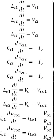
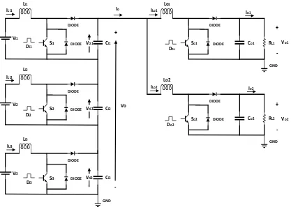
![Figure 4.2 The proposed MIMO step-up DC transformer topology [123]](https://thumb-us.123doks.com/thumbv2/123dok_us/565890.556045/83.595.128.536.99.394/figure-the-proposed-mimo-step-dc-transformer-topology.webp)


![Figure 4.11 the IGBT module power losses hierarchy [130]](https://thumb-us.123doks.com/thumbv2/123dok_us/565890.556045/105.595.112.525.42.347/figure-igbt-module-power-losses-hierarchy.webp)
