applied
sciences
Article
The Influence of Valve-Pump Weight Ratios on the
Dynamic Response of Leaking Valve-Pump Parallel
Control Hydraulic Systems
Haigang Ding1, Jiyun Zhao1,*, Gang Cheng1, Steve Wright2and Yufeng Yao2
1 School of Mechatronic Engineering, China University of Mining and Technology, Xuzhou 221116, China; [email protected] (H.D.); [email protected] (G.C.)
2 Department of Engineering Design and Mathematics, University of the West of England, Bristol BS16 1QY, UK; [email protected] (S.W.); [email protected] (Y.Y.)
* Correspondence: [email protected]; Tel.: +86-516-8359-0777
Received: 18 May 2018; Accepted: 13 July 2018; Published: 22 July 2018
Abstract:A new leaking valve-pump parallel control (LVPC) oil hydraulic system is proposed to improve the performance of dynamic response of present variable speed pump control (VSPC) system, which is an oil hydraulic control system with saving energy. In the LVPC, a control valve is operating at leaking status, together with a variable speed pump, to regulate the system flow of hydraulic oil simultaneously. Therefore, the degree of valve control and pump control can be adjusted by regulating the valve-pump weight ratio. The LVPC system design, mathematical model development, system parameter and control performance analysis are carried out systematically followed by an experimental for validation process. Results have shown that after introducing the valve control, the total leakage coefficient increases significantly over a wide range with the operating point and this further increases damping ratios and reduces the velocity stiffness. As the valve-pump weight ratio determines the flow distribution between the valve and the pump and the weight factors of the valve and/or the pump controls determines the response speed of the LVPC system, thus if the weight factors are constrained properly, the LVPC system will eventually have a large synthetic open-loop gain and it will respond faster than the VSPC system. The LVPC will enrich the control schemes of oil hydraulic system and has potential value in application requiring of fast response.
Keywords: rapid response; leaking valve-pump parallel control; variable speed pump control; parallel valve control; valve-pump weight ratio
1. Introduction
Traditional hydraulic control systems are of two basic types: pump control and valve control [1]. Valve control systems respond quickly to valve and load inputs but are less efficient due to throttling and overflow losses [2,3]. Pump control systems work efficiently since both system pressure and flow are closely matched with load requirements [4,5] but have a critical drawback: slow response. The variable speed pump control (VSPC) system is a new class of pump control system, using a variable speed motor to drive a fixed displacement pump, which is applicable to hydraulic elevators [6], shield tunneling machine [7] and water distribution systems [8,9]. Compared with traditional pump control systems, the VSPC system has advantages of lower cost, higher reliability and higher energy-efficiency. However, response time is poor, due to the high inertia of the electric motor and the low overload capacity of the inverter driving it, preventing their use in applications requiring rapid response.
Two classes of combined valve-pump control may be identified: serial control and parallel control, balancing the respective advantages of each, with respect to dynamic response and energy efficiency [10]. To accelerate the response of VSPC systems, Manasek [11] proposes a valve-pump series
control system, in which a flow control valve is connected in series to the outlet of the pump. Shen et al. propose a variable speed hydraulic control system based on an energy regulation strategy [12,13], in which an energy regulation device releases energy to improve dynamic response serial valve-pump control systems are not suitable for high power systems, due to the control valve installed in the main circuit limiting maximum flow of the system. However, valve-pump parallel control systems can avoid this disadvantage, as the parallel control valve in the main circuit does not limit the system flow. Recent research on parallel control systems mainly focus on electrohydraulic actuators in a hybrid primary flight control system [14,15]. The current parallel control system is of a replenishing type, requiring an additional oil supply device and current research does not explain the role of pump control and valve control in the combined system and its corresponding influences on dynamic response.
To improve the response of VSPC systems, this paper develops a leaking valve-pump parallel control (LVPC) system, in which a leaking control valve is placed in parallel to a variable speed pump to collectively regulate system flow. In the paper, the LVPC system is designed and its working principles explained. Mathematical models are constructed, an experimental system set up and the influence of different valve-pump weights on system response are discussed, demonstrating the role of pump and valve control in the combined system. Thus, the LVPC provides a new method for improving dynamic response of pump control systems and will enrich the control schemes of hydraulic systems. LVPC might have potential value in application requiring of fast response. Beyond the particular application on a hydraulic test rig for volumetric machines, the same method could be maybe applied on a turbomachinery test rig to regulate for example the head of the testing model, which are classically also equipped either with a variable speed pump.
2. Methods
2.1. Principle of Proposed System
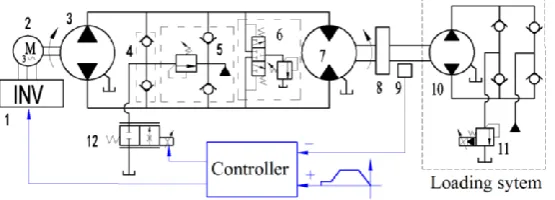
The schematic diagram of the LVPC is shown in Figure1, its main circuit is a variable speed pump control motor circuit and a proportional throttle valve (PTV) is connected in parallel to the main circuit through a shuttle valve and forms a bypass leakage path. In the parallel control system, the variable speed pump (VSP) supplies a basic flow, which is varied via the output frequency of the inverter and the individual replenishing device is connected to the return chamber to compensate for leakage and maintain a constant chamber pressure. The flushing device is used to exchange hot fluid in the return chamber and to cool the system.
Appl. Sci. 2017, 7, x FOR PEER REVIEW 3 of 14
If 𝐾𝑣𝑝 > 1, the role of the valve control is greater than that of the pump control and the system
is mainly controlled by the PTV. When 𝐾𝑣: 𝐾𝑝= 1:0, the combined system becomes a conventional
valve control system, totally controlled by the valve.
Conversely, if 𝐾𝑣𝑝 < 1, the role of the pump control is greater than that of the valve control and
the system is mainly controlled by the VSP, a ratio of 𝐾𝑣: 𝐾𝑝= 0:1 implying a conventional VSPC
[image:2.595.161.439.536.636.2]system.
Figure 1.Schematic framework of LVPC (leaking valve-pump parallel control) system. 1—Inverter; 2—electric motor; 3—Fixed displacement pump; 4—Shuttle valve; 5—Oil replenishing device; 6— Flushing device; 7—Hydraulic motor; 8—Inertia; 9—Encoder; 10—Loading pump; 11—Proportional relief valve; 12—PTV (proportional throttle valve).
Figure 2.Control principle of leaking valve-pump parallel control. 2.2. Mathematical Formulations
2.2.1. Inverter-Electric Motor Link
The inverter-electric motor link may be regarded as a first-order inertia element
𝑛𝑝=
𝐾𝑢𝑢𝑝− 𝐾ℎ𝑃ℎ
𝑠 𝜔𝑏𝑝+ 1
(2)
where 𝑛𝑝 is the electric motor speed, 𝑢𝑝is the input voltage of the inverter, 𝐾𝑢is the coefficient of
voltage, 𝑃ℎis the high-pressure chamber pressure of the system, 𝐾ℎ is the coefficient of pressure and
𝜔𝑏𝑝is the break frequency, which is inversely proportional to the pump inertia.
Equation (2) indicates that 𝑛𝑝 increases with increasing 𝑢𝑝 and decreasing 𝑃ℎ and the actual
flow of the pump 𝑞𝑝 is given by
𝑞𝑝= 𝑞𝑝0− 𝐶𝑝𝑃ℎ (3)
where 𝑞𝑝0= 𝐷𝑝𝑛𝑝, is the unload flow of the pump and when the system runs under no load, 𝑃ℎ=
0, thus 𝑞𝑝0= 𝐷𝑝𝐾𝑢𝑢𝑝
𝑠 𝜔𝑏𝑝+1
, in which 𝐷𝑝is the pump displacement and 𝐶𝑝is the total leakage coefficient of
the pump.
2.2.2. Parallel Valve Control Circuit
The orifice flow equation of the PTV can be expressed as
𝑞𝑣= 𝐶𝑠𝑣𝑢𝑣√𝑃ℎ (4)
𝐾
𝑝𝐾
𝑣Ref.
PTV
VSP Hydraulic motor
Speed feedback
Speed
Figure 1.Schematic framework of LVPC (leaking valve-pump parallel control) system. 1—Inverter; 2—electric motor; 3—Fixed displacement pump; 4—Shuttle valve; 5—Oil replenishing device; 6—Flushing device; 7—Hydraulic motor; 8—Inertia; 9—Encoder; 10—Loading pump; 11—Proportional relief valve; 12—PTV (proportional throttle valve).
Appl. Sci.2018,8, 1201 3 of 14
the bypass flow back to the tank though the control valve. In order to distinguish the role of valve control and pump control in the combined system, the valve-pump weight ratioKvpis given as
Kvp =Kv:Kp (1)
where Kv is the weight factor of the valve control link and Kp is the weight factor of the pump control link.
Appl. Sci. 2017, 7, x FOR PEER REVIEW 3 of 14
If 𝐾𝑣𝑝 > 1, the role of the valve control is greater than that of the pump control and the system
is mainly controlled by the PTV. When 𝐾𝑣: 𝐾𝑝= 1:0, the combined system becomes a conventional
valve control system, totally controlled by the valve.
Conversely, if 𝐾𝑣𝑝 < 1, the role of the pump control is greater than that of the valve control and
the system is mainly controlled by the VSP, a ratio of 𝐾𝑣: 𝐾𝑝= 0:1 implying a conventional VSPC
system.
[image:3.595.153.442.189.269.2]Figure 1.Schematic framework of LVPC (leaking valve-pump parallel control) system. 1—Inverter; 2—electric motor; 3—Fixed displacement pump; 4—Shuttle valve; 5—Oil replenishing device; 6— Flushing device; 7—Hydraulic motor; 8—Inertia; 9—Encoder; 10—Loading pump; 11—Proportional relief valve; 12—PTV (proportional throttle valve).
Figure 2.Control principle of leaking valve-pump parallel control. 2.2. Mathematical Formulations
2.2.1. Inverter-Electric Motor Link
The inverter-electric motor link may be regarded as a first-order inertia element
𝑛𝑝=
𝐾𝑢𝑢𝑝− 𝐾ℎ𝑃ℎ
𝑠 𝜔𝑏𝑝+ 1
(2)
where 𝑛𝑝 is the electric motor speed, 𝑢𝑝is the input voltage of the inverter, 𝐾𝑢is the coefficient of
voltage, 𝑃ℎis the high-pressure chamber pressure of the system, 𝐾ℎ is the coefficient of pressure and
𝜔𝑏𝑝is the break frequency, which is inversely proportional to the pump inertia.
Equation (2) indicates that 𝑛𝑝 increases with increasing 𝑢𝑝 and decreasing 𝑃ℎ and the actual
flow of the pump 𝑞𝑝 is given by
𝑞𝑝= 𝑞𝑝0− 𝐶𝑝𝑃ℎ (3)
where 𝑞𝑝0= 𝐷𝑝𝑛𝑝, is the unload flow of the pump and when the system runs under no load, 𝑃ℎ =
0, thus 𝑞𝑝0= 𝐷𝑝𝐾𝑢𝑢𝑝
𝑠 𝜔𝑏𝑝+1
, in which 𝐷𝑝is the pump displacement and 𝐶𝑝is the total leakage coefficient of
the pump.
2.2.2. Parallel Valve Control Circuit
The orifice flow equation of the PTV can be expressed as
𝑞𝑣= 𝐶𝑠𝑣𝑢𝑣√𝑃ℎ (4)
𝐾
𝑝𝐾
𝑣Ref.
PTV
VSP Hydraulic motor
Speed feedback
Speed
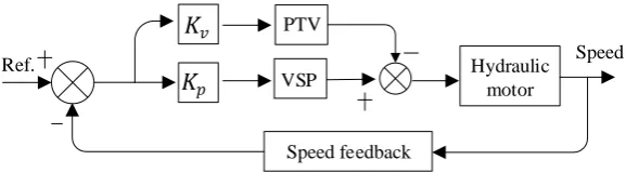
Figure 2.Control principle of leaking valve-pump parallel control.
The LVPC system is a multi-input and output control system, is composed of valve control and pump control and each control link is in closed-loop control. The encoder detects the actual speed of the motor and feeds back to the controller. The actual speed is compared with the reference speed to obtain the speed error. This error is assigned to the valve control channel and the pump control channel according to the weight ratio and under the common adjustment of valve control and pump control, the motor reaches a certain desired speed.
IfKvp> 1, the role of the valve control is greater than that of the pump control and the system is mainly controlled by the PTV. WhenKv:Kp= 1:0, the combined system becomes a conventional valve control system, totally controlled by the valve.
Conversely, ifKvp< 1, the role of the pump control is greater than that of the valve control and the system is mainly controlled by the VSP, a ratio ofKv:Kp= 0:1 implying a conventional VSPC system.
2.2. Mathematical Formulations 2.2.1. Inverter-Electric Motor Link
The inverter-electric motor link may be regarded as a first-order inertia element
np=
Kuup−KhPh
s ωbp
+1 (2)
wherenpis the electric motor speed,upis the input voltage of the inverter,Ku is the coefficient of voltage,Phis the high-pressure chamber pressure of the system,Khis the coefficient of pressure and ωbpis the break frequency, which is inversely proportional to the pump inertia.
Equation (2) indicates thatnpincreases with increasingupand decreasingPhand the actual flow of the pumpqpis given by
qp=qp0−CpPh (3)
where qp0 = Dpnp, is the unload flow of the pump and when the system runs under no load,
Ph = 0, thus qp0 =
DpKuup s ωbp+1
2.2.2. Parallel Valve Control Circuit
The orifice flow equation of the PTV can be expressed as
qv=Csvuv
p
Ph (4)
whereCsvis the valve constant anduvis the control voltage corresponding to spool displacement. The orifice flow equation is nonlinear, using the Taylor series method for linearizing Equation (4) at the null operation point and the linearized flow equation is given by
qv=Kquv+KcPh
Kq= ∂qv ∂uv
=Csv √
Ph
Kc= ∂qv ∂Ph =Csv
uv 2√Ph
(5)
whereKq is the flow gain,Kcis the pressure-pressure-flow coefficient. The coefficientsKq andKc are known as the valve coefficients and are extremely important for determine the valve’s stability, frequency response and other dynamic characteristics.
In generally, proportional valves are considered as a second-order oscillating link in the hydraulic control system and the control valve’s unload flow is given by
qv0=
Kquv
s2 ωv2
+2ξv ωvs
+1
(6)
whereqv0, ωvandξvis its unload flow, hydraulic natural frequency and damping ratio and its unload flow is promotional to the control inputuv, which corresponds to the opening of the control valve. 2.2.3. Valve-Pump Parallel Control Motor Link
The continuity equation for the whole system is
qp−qv=CmPh+Dmω+V0sPh/βe (7) whereωis the motor angular speed,Cmis the motor leakage coefficient,Dmis the motor displacement andV0is the average volume of high-pressure chamber.
The torque balance equation for the hydraulic motor is
DmPh=Jsω+Bmω+TL (8)
whereJis the equivalent total inertia,Bmis the viscous damping coefficient,TL =DLPhis the load torque produced by the loading pump (ignoring the low-pressure chamber pressure) andDL=Dmis the displacement of the loading pump.
Combining (3), (5), (6), (7) and (8), the open loop dynamic equation for the LVPC [16] is given by:
ω=
Kpqp0−Kvqv0
Dm −
Cl
Dm2
1+ s
2ωlξl
TL
s2 ωl2
+2ξl ωl
s+1
(9)
whereCl =Cp+Cm+Kc,ωl =
q
βeDm2 V0 J ,ξl =
Cl
2Dm
q
βe J
Appl. Sci.2018,8, 1201 5 of 14
When the PTV is closed andKv=0, Kp=1, such thatKvp=0and qv0andKcwill be zero in (9), the system control mode will change from LVPC to VSPC and its open loop dynamic equation [17] is
ω=
qp0
Dm − Ct
Dm2
1+ s
2ωmξm
TL
s2 ωm2
+2ξm ωms
+1
(10)
whereCt=Cp+Cm, ωl=
q
βeDm2 V0 J ,ξm=
Ct 2Dm
q
βe J
V0 ,Cm,ξmandωmare the total leakage coefficient, damping ratio and hydraulic natural frequency of the VSPC system respectively. Equations (9) and (10) indicate that a VSPC may be considered a special case of an LVPC. Notice that the linearized Equations 9 and 10 are valid around a specific operating point, for the real behavior is strongly nonlinear. Moreover, in these equations, the natural frequency can be computed with fair confidence but the damping ratio especiallyξlis much more variable and nebulous.
The rotary component is simplified as a proportional element due to its fast response:
Km= um
nm (11)
where um is the feedback voltage, Km is the feedback gain and nm = 30 ω/π is the motor’s angular velocity.
2.2.4. Total System Mathematical Model
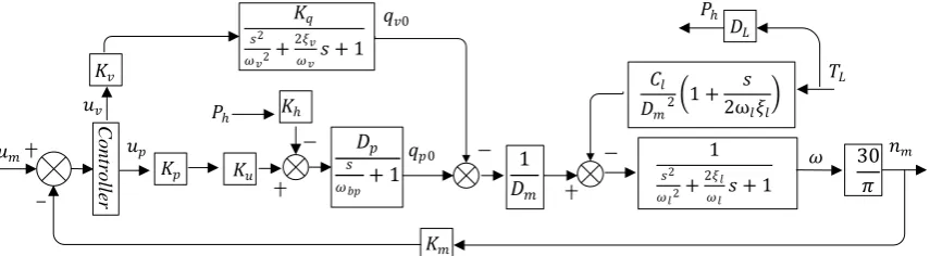
The block diagram of the parallel control system is obtained by combining the three links above, as shown in Figure3. The block diagram indicates that the parallel valve-pump system is a type-0 system and the valve and pump control links are all unstable, requiring the two links to be corrected in order to obtain sound control performance. The simplest method, integral correction, is used here.
Appl. Sci. 2017, 7, x FOR PEER REVIEW 5 of 14
(10) indicate that a VSPC may be considered a special case of an LVPC. Notice that the linearized Equations 9 and 10 are valid around a specific operating point, for the real behavior is strongly nonlinear. Moreover, in these equations, the natural frequency can be computed with fair confidence but the damping ratio especially 𝜉𝑙 is much more variable and nebulous.
The rotary component is simplified as a proportional element due to its fast response:
𝐾𝑚=
𝑢𝑚
𝑛𝑚 (11)
where 𝑢𝑚 is the feedback voltage, 𝐾𝑚 is the feedback gain and 𝑛𝑚= 30 ω/πis the motor’s angular
velocity.
2.2.4. Total System Mathematical Model
The block diagram of the parallel control system is obtained by combining the three links above, as shown in Figure 3. The block diagram indicates that the parallel valve-pump system is a type-0 system and the valve and pump control links are all unstable, requiring the two links to be corrected in order to obtain sound control performance. The simplest method, integral correction, is used here. After correction, the open loop transfer functions of the valve control link and pump control link are respectively given by:
𝐺𝑣𝑘 =
𝐾𝑠𝑣
𝑠(𝜔𝑠2
𝑣2+
2𝜉𝑣
𝜔𝑣 𝑠 + 1)(
𝑠2
𝜔𝑙2+
2𝜉𝑙
𝜔𝑙𝑠 + 1)
(12)
𝐺𝑝𝑘=
𝐾𝑠𝑝
𝑠(𝜔𝑠
𝑏𝑝+ 1)(
𝑠2
𝜔𝑙2+
2𝜉𝑙
𝜔𝑙𝑠 + 1)
(13)
where 𝐾𝑠𝑣 𝑖𝑠 the open loop gain of the corrected valve control link, 𝑎𝑛𝑑 𝐾𝑠𝑣= 30 𝐾𝑚𝐾𝑣𝐼𝐾𝑞/(𝜋𝐷𝑚),
in which 𝐾𝑣𝐼is the integral gain of the valve control link, 𝐾𝑠𝑝 𝑖𝑠 the open loop gain of the corrected
pump control link, 𝑎𝑛𝑑 𝐾𝑠𝑝= 30 𝐾𝑚𝐾𝑝𝐼𝐾𝑢𝐷𝑝/(𝜋𝐷𝑚), in which 𝐾𝑝𝐼is the integral gain of the pump
control link.
The LVPC system is a multiple input single output (MISO) system. To facilitate the study, the system could be assumed a linear system that satisfies the superposition principle, that is the total output produced by multiple inputs is equal to the sum of the outputs produced by a single input. Specific to this system, LVPC can be viewed as a superposition of a pump controlled motor and a valve controlled motor, so the o integrated pen-loop gain of the combined system 𝐾𝑠𝑙 is equal to the
sum of the valve-controlled open-loop gain 𝐾𝑠𝑣and the pump-controlled open-loop gain 𝐾𝑠𝑝.
𝐾𝑠𝑙= 𝐾𝑣𝐾𝑠𝑣+ 𝐾𝑝𝐾𝑠𝑝 (14)
In the equation, 𝐾𝑣 and 𝐾𝑝 are used to adjust the proportion of pump control and valve control.
The velocity stiffness of the LVPC system is given by
|𝑇𝐿 𝑛𝑚
|
𝑙
=𝐾𝑠𝑙𝐷𝑚
2 𝐶𝑙 (15) C ontr oll er 𝐾𝑞 𝑠2
𝜔𝑣2+ 2𝜉𝑣
𝜔𝑣𝑠+ 1
𝑞𝑣0
𝑢𝑣 𝑃ℎ
𝐾𝑢
𝐾ℎ
𝐷𝑝 𝑠 𝜔𝑏𝑝 + 1
𝑞𝑝0
𝐾𝑚 1 𝐷𝑚 𝐷𝐿 𝑃ℎ 𝑇𝐿 30 𝜋 𝐶𝑙
𝐷𝑚2
1 + 𝑠 2ω𝑙𝜉𝑙 1 𝑠2
𝜔𝑙2+ 2𝜉𝑙
𝜔𝑙𝑠+ 1
𝑢𝑝
𝑢𝑚 𝜔 𝑛𝑚
𝐾𝑝
[image:5.595.85.513.452.570.2]𝐾𝑣
Figure 3.Block diagram of LVPC system.
After correction, the open loop transfer functions of the valve control link and pump control link are respectively given by:
Gvk =
Ksv
s( s 2
ωv2 +2ξv
ωvs
+1)( s 2
ωl2 +2ξl
ωl
s+1)
(12)
Gpk=
Ksp
s( s ωbp
+1)( s 2
ωl2 +2ξl
ωl
s+1)
(13)
pump control link,and Ksp =30KmKpIKuDp/(πDm), in whichKpIis the integral gain of the pump control link.
The LVPC system is a multiple input single output (MISO) system. To facilitate the study, the system could be assumed a linear system that satisfies the superposition principle, that is the total output produced by multiple inputs is equal to the sum of the outputs produced by a single input. Specific to this system, LVPC can be viewed as a superposition of a pump controlled motor and a valve controlled motor, so the o integrated pen-loop gain of the combined systemKslis equal to the sum of the valve-controlled open-loop gainKsvand the pump-controlled open-loop gainKsp.
Ksl =KvKsv+KpKsp (14)
In the equation,KvandKpare used to adjust the proportion of pump control and valve control. The velocity stiffness of the LVPC system is given by
TL
nm
l
= KslDm 2
Cl
(15)
2.3. System Parameter Analysis
After adding a valve control to a VSPC system, the parameters of LVPC systems will have the following characteristics:
(1) Identical hydraulic natural frequency. Equations (9) and (10) indicate that the introduction of valve control does not change the system’s hydraulic natural frequency and the LVPC system has the same hydraulic natural frequency as the VSPC system.
(2) Larger and variable total leakage coefficients. In general, total leakage coefficients of pump control systemsCtis small and stable. However, after introducing valve control, the total leakage coefficient of LVPC systems becomes larger and varies widely with system pressurePhand control inputsuv. This is due to the pressure-flow gainKcbeing much greater compared toCtand changing withPhanduv, according toKc=Csvuv/ 2
√ Ph
.
(3) Greater and variable damping ratios. Because the damping ratio is proportional to the total leakage coefficient, the damping ratio of LVPC systems is much greater than that of VSPC systems and varies widely withPhanduv. Greater damping ratios will benefit system stability but values will cause difficulty with parameter prediction and system control.
(4) Lower velocity stiffness. Equation (15) indicates that velocity stiffness decreases with the increase of total leakage coefficients andCtCl. Thus, compared with VSPC systems, LVPC systems have lower velocity stiffness and will be more susceptible to load disturbance.
(5) Faster dynamic response. It is well known that increasing open loop gain will speed system response. As long as the weight factorsKvand Kpare appropriate, the open loop gain of LVPC systems will always be greater than that of VSPC systems (i.e.Ksl>Ksp) and therefore the LVPC system will respond faster than the VSPC system.
3. Case Studies
3.1. Experiment
Appl. Sci.2018,8, 1201 7 of 14
block is installed between the two hydraulic motors, its total weight being 900 kg and its total inertia 72 kg·m2. In order to study dynamic response under different inertias, the inertia block is designed to be modular, with one basic and four small blocks.Appl. Sci. 2017, 7, x FOR PEER REVIEW 7 of 14
[image:7.595.85.522.142.280.2] [image:7.595.72.518.341.440.2](a) (b)
Figure 4. Experimental system. (a) A view of the experimental system; (b) Loading system.
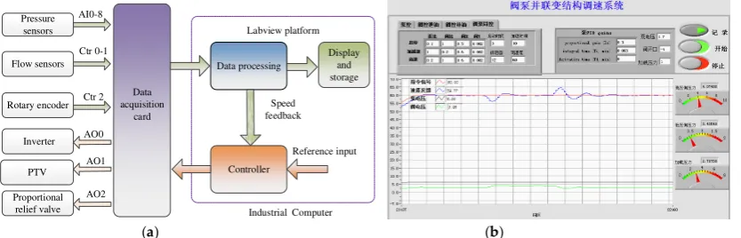
A virtual control system is developed using the LabVIEW platform as shown in Figure 5. The system pressures, pump flow rates, valve flow and hydraulic motor’s rotary speed are measured by corresponding sensors and are fed back to an industrial computer via a data acquisition card. After data processing, the control system outputs control signals to the inverter, PTV and PRV. The control system integrates the functions of data acquisition, control, display and data storage and can work under LVPC and VSPC modes.
Data acquisition card Pressure sensors Flow sensors Rotary encoder Inverter PTV Proportional relief valve Data processing Controller Display and storage Reference input Ctr 0-1 AI0-8 AO0 AO1 AO2 Labview platform
Industrial Computer Speed feedback Ctr 2
[image:7.595.92.509.549.683.2](a) (b)
Figure 5. Measurement and control system. (a) Control principle; (b) Interface.
From Section 2.2, we know that the valve-pump parallel system is a type-0 system and is unstable before compensation, so the PI compensation is applied to the pump control circuit and valve control circuit. The PI transfer function is
𝐺𝑐= 𝐾𝑝 1 +
1 𝑇𝑖𝑠
= 𝐾𝑝+
𝐾𝐼
𝑠 (16)
where 𝐾𝑝is the proportional gain, 𝑇𝑖is the internal time, 𝐾𝐼 is the internal gain and 𝐾𝐼= 𝐾𝑝/𝑇𝑖. Thus
𝐾𝐼is defined by 𝐾𝑝 and 𝑇𝑖.
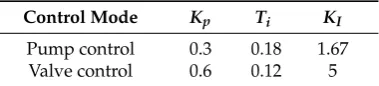
Step response experiments of the valve control and the pump control circuits are carried out as shown in Figure 6,and optimal PI parameters are obtained through repeated experiments, as shown in Table 2. A relationship, 𝐾𝐼≫ 𝐾𝑝 is maintained in the two control circuits, so PI compensation can
be considered as an internal compensation mechanism, as discussed in Section 2.2.4. The experimental results show that the selected PI parameters are reasonable and the valve control responds faster than the pump control.
Table 2. Coefficients of PI under different mode.
Control Mode 𝑲𝒑 𝑻𝒊 𝑲𝑰
Pump control 0.3 0.18 1.67 Valve control 0.6 0.12 5
Figure 4.Experimental system. (a) A view of the experimental system; (b) Loading system.
Table 1.System configuration.
Components Specification
Electric motor power:7.5 Kw; rated speed:3000 r/min; control voltage: 0–10 V Inverter power:11 kW with vector control; frequency range:0.1–100 Hz; Fixed pump displacement:12.6 mL/r; speed range:500–3000 r/min
Hydraulic motor speed range: 0–90 r/min; displacement:468 mL/r; rated pressure: 40 MPa PTV rate flow: 9 L/min at 1.5 MPa per notch; frequency: 60 Hz; damping ratio: 0.7 Proportional relief valve pressure rang: 0.7–31.5 MPa; rate flow:200 L/min
Rotary inertia 72 kg·m2
A virtual control system is developed using the LabVIEW platform as shown in Figure 5. The system pressures, pump flow rates, valve flow and hydraulic motor’s rotary speed are measured by corresponding sensors and are fed back to an industrial computer via a data acquisition card. After data processing, the control system outputs control signals to the inverter, PTV and PRV. The control system integrates the functions of data acquisition, control, display and data storage and can work under LVPC and VSPC modes.
Appl. Sci. 2017, 7, x FOR PEER REVIEW 7 of 14
(a) (b)
Figure 4. Experimental system. (a) A view of the experimental system; (b) Loading system.
A virtual control system is developed using the LabVIEW platform as shown in Figure 5. The system pressures, pump flow rates, valve flow and hydraulic motor’s rotary speed are measured by corresponding sensors and are fed back to an industrial computer via a data acquisition card. After data processing, the control system outputs control signals to the inverter, PTV and PRV. The control system integrates the functions of data acquisition, control, display and data storage and can work under LVPC and VSPC modes.
Data acquisition card Pressure sensors Flow sensors Rotary encoder Inverter PTV Proportional relief valve Data processing Controller Display and storage Reference input Ctr 0-1 AI0-8 AO0 AO1 AO2 Labview platform
Industrial Computer Speed feedback Ctr 2
(a) (b)
Figure 5. Measurement and control system. (a) Control principle; (b) Interface.
From Section 2.2, we know that the valve-pump parallel system is a type-0 system and is unstable before compensation, so the PI compensation is applied to the pump control circuit and valve control circuit. The PI transfer function is
S*= `1 +81
da = +
X
(16)
where is the proportional gain, 8dis the internal time, X is the internal gain and X= /8d. Thus
Xis defined by and 8d.
Step response experiments of the valve control and the pump control circuits are carried out and optimal PI parameters are obtained through repeated experiments, as shown in Table 2. A relationship, X≫ is maintained in the two control circuits, so PI compensation can be considered as an internal compensation mechanism, as discussed in Section 2.2.4. The experimental results show that the selected PI parameters are reasonable and the valve control responds faster than the pump control.
Table 2. Coefficients of PI under different mode.
Control Mode fg hi fj
Pump control 0.3 0.18 1.67
Valve control 0.6 0.12 5
Commented [WU8]: We change the location of explanation
of (a) (b) and (c). Please confirm.
Commented [WU9]: We change the location of explanation
of (a) (b) and (c). Please confirm.
Figure 5.Measurement and control system. (a) Control principle; (b) Interface.
Gc=Kp
1+ 1 Tis
=Kp+KI
s (16)
whereKpis the proportional gain,Tiis the internal time,KIis the internal gain andKI =Kp/Ti. Thus
KIis defined byKpandTi.
Step response experiments of the valve control and the pump control circuits are carried out as shown in Figure6, and optimal PI parameters are obtained through repeated experiments, as shown in Table2. A relationship,KI Kpis maintained in the two control circuits, so PI compensation can be considered as an internal compensation mechanism, as discussed in Section2.2.4. The experimental results show that the selected PI parameters are reasonable and the valve control responds faster than the pump control.
Appl. Sci. 2017, 7, x FOR PEER REVIEW 8 of 14
(a)
[image:8.595.121.480.243.646.2](b)
Figure 6. Step response of pump control and valve control. (a) Pump control circuit; (b) Valve control circuit.
3.2. Results and Discussion
3.2.1. Step Responses to Reference Inputs
In order to investigate the dynamic response characteristics of LVPC systems, experiments in
step responses to reference inputs for different weight ratios 𝐾
𝑣𝑝are carried out, as shown in Figure
7. The experimental condition is described as follows: the initial voltage of the pump
𝑢
𝑝0= 7.2 V, the
initial voltage of the valve
𝑢
𝑣0=
−
5.8 V, the system pressure
𝑃
ℎ= 4.2
–
5 MPa and PI parameters of
valve control circuit and pump control circuit are set as in Table 2. Taking
𝐾
𝑣𝑝= 1 as the axis of
symmetry, on the left side of the axis, there is
𝐾
𝑣𝑝> 1 and the combined system is mainly dominated
by the PTV and when
𝐾
𝑣: 𝐾
𝑝= 1:0, the combined system is totally controlled by the valve; on the right
of the axis, there is
𝐾
𝑣𝑝< 1 and the combined system is mainly dominated by the VSP and when
𝐾
𝑣: 𝐾
𝑝= 0:1, the combined system is totally controlled by the pump. The following rules can be
obtained:
(1) The step response to reference inputs
are of pyramid form, both ends respond slowly, the
middle responds fast and LVPC responds faster than the single valve control and the single pump
control. That is due to the weight factor
𝐾
𝑝or
𝐾
𝑣being equal to 1 in the experiment and
𝐾
𝑠𝑙>
𝐾
𝑠𝑣𝑜𝑟 𝐾
𝑠𝑙> 𝐾
𝑠𝑝is maintained in Equation (14), when the bigger
𝐾
𝑝+𝐾
𝑣, the larger the
𝐾
𝑠𝑙, the faster
the LVPC system responds.
(2) For the same sum of weight factors, the response mainly based on valve control is greater
than that based on pump control. That is because
𝐾
𝑠𝑣> 𝐾
𝑠𝑝, for the same of sum of weight factor
(𝐾
𝑣+ 𝐾
𝑝) and the synthetic open-loop gain of the symmetrical axis on the left side (mainly based on
[image:8.595.203.393.705.748.2]valve control) is larger than that on the right side (mainly by pump control).
Figure 6.Step response of pump control and valve control. (a) Pump control circuit; (b) Valve control circuit.
Table 2.Coefficients of PI under different mode.
Control Mode Kp Ti KI
Pump control 0.3 0.18 1.67
Appl. Sci.2018,8, 1201 9 of 14
3.2. Results and Discussion
3.2.1. Step Responses to Reference Inputs
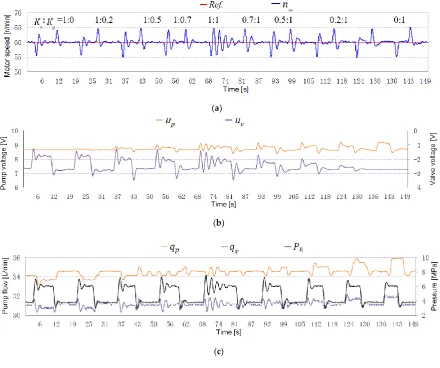
In order to investigate the dynamic response characteristics of LVPC systems, experiments in step responses to reference inputs for different weight ratiosKvpare carried out, as shown in Figure7. The experimental condition is described as follows: the initial voltage of the pumpup0= 7.2 V, the initial voltage of the valveuv0=−5.8 V, the system pressurePh= 4.2–5 MPa and PI parameters of valve control circuit and pump control circuit are set as in Table2. TakingKvp=1 as the axis of symmetry, on the left side of the axis, there isKvp >1 and the combined system is mainly dominated by the PTV and whenKv:Kp= 1:0, the combined system is totally controlled by the valve; on the right of the axis, there isKvp <1 and the combined system is mainly dominated by the VSP and whenKv:Kp= 0:1, the combined system is totally controlled by the pump. The following rules can be obtained:
Appl. Sci. 2017, 7, x FOR PEER REVIEW 9 of 14
(3) The valve-pump weight ratio determines the flow distribution relationship of the valve and the pump. This can be verified from Figure 7 (b) and (c), from 𝐾𝑣: 𝐾𝑝 = 1:0 to 𝐾𝑣: 𝐾𝑝 = 0:1,
𝐾𝑣𝑝gradually decreases, the valve control effect decreases as pump control effect increases, so valve
flow gradually decreases and pump flow gradually increases.
The step response experiments under the same weight ratio 𝐾𝑣𝑝 are also carried out, as shown
in Figure 8 and the following rules can be obtained.
(1) Under the same weight ratio, the response speed of the LVPC system is proportional to the weight factors of the valve control and the pump control. For example, when 𝐾𝑣: 𝐾𝑝 = 0.2:0.2, the
LVPC system responds slowest and when 𝐾𝑣: 𝐾𝑝 = 1:1, the LVPC system responds fastest but the
overshoot will be larger and stability is degraded when 𝐾𝑣 and 𝐾𝑝 are too great. That is because,
according to equation (14), 𝐾𝑣 and 𝐾𝑝 determine 𝐾𝑠𝑙 𝑎𝑛𝑑 𝐾𝑠𝑙 determines the response speed of the
combined system.
(2) Under the same weight ratio, the weight factor does not affect the valve flow and pump flow in the stable state and the ratio between valve flow and pump flow remains constant but great weight factor will cause a high-pressure response. For example, from 𝐾𝑣: 𝐾𝑝 = 0.2:0.2 to 𝐾𝑣: 𝐾𝑝 = 1:1, the
stable flow in pump control is always 28 L/min and stable leakage flow in the valve control is always 7.5 L/min.
(a)
(b)
(c)
[image:9.595.80.515.269.656.2]Figure 7. Step response to reference inputs under different weight ratios 𝐾𝑣𝑝. (a) Motor speed response; (b) Pump and valve voltage variation; (c) System pressure and flow response.
Figure 7.Step response to reference inputs under different weight ratiosKvp. (a) Motor speed response;
(b) Pump and valve voltage variation; (c) System pressure and flow response.
(1) The step response to reference inputs are of pyramid form, both ends respond slowly, the middle responds fast and LVPC responds faster than the single valve control and the single pump control. That is due to the weight factor Kp orKv being equal to 1 in the experiment and
(2) For the same sum of weight factors, the response mainly based on valve control is greater than that based on pump control. That is becauseKsv > Ksp, for the same of sum of weight factor (Kv+Kp) and the synthetic open-loop gain of the symmetrical axis on the left side (mainly based on valve control) is larger than that on the right side (mainly by pump control).
(3) The valve-pump weight ratio determines the flow distribution relationship of the valve and the pump. This can be verified from Figure7b,c, fromKv :Kp= 1:0 toKv :Kp= 0:1,Kvpgradually decreases, the valve control effect decreases as pump control effect increases, so valve flow gradually decreases and pump flow gradually increases.
The step response experiments under the same weight ratioKvpare also carried out, as shown in FigureAppl. Sci. 82017and the following rules can be obtained., 7, x FOR PEER REVIEW 10 of 14
(a)
(b)
(c)
Figure 8. Step response to reference inputs when 𝐾𝑣𝑝= 1. (a) Motor speed response; (b) Pump and
valve voltage variation; (c) System pressure and flow response.
3.2.2. Step Responses to Loads
After the experiments in step responses to reference inputs, step responses to loads under different and equal vales of 𝐾𝑣𝑝are carried out, as shown in Figure 9 and 10. Experimental condition
are as follows: initial pump voltage 𝑢𝑝0= 8.6 V, initial valve voltage 𝑢𝑣0= −2.8 V and PI parameters
of the control circuit are set as in Table 2. The reference speed of the hydraulic motor is set to 60 r/min, pressure disturbance is generated by the PRV and the high-pressure side of the system produces step pressures from 4 MPa to 6 MPa and 6 MPa to 4 MPa.
(a)
Figure 8.Step response to reference inputs whenKvp=1. (a) Motor speed response; (b) Pump and
valve voltage variation; (c) System pressure and flow response.
[image:10.595.79.521.229.630.2]Appl. Sci.2018,8, 1201 11 of 14
weight factor will cause a high-pressure response. For example, fromKv:Kp= 0.2:0.2 toKv:Kp= 1:1, the stable flow in pump control is always 28 L/min and stable leakage flow in the valve control is always 7.5 L/min.
3.2.2. Step Responses to Loads
After the experiments in step responses to reference inputs, step responses to loads under different and equal vales ofKvpare carried out, as shown in Figures9and10. Experimental condition are as follows: initial pump voltageup0 =8.6 V, initial valve voltageuv0 =−2.8 V and PI parameters of the control circuit are set as in Table2. The reference speed of the hydraulic motor is set to 60 r/min, pressure disturbance is generated by the PRV and the high-pressure side of the system produces step pressures from 4 MPa to 6 MPa and 6 MPa to 4 MPa.
Appl. Sci. 2017, 7, x FOR PEER REVIEW 10 of 14
(a)
(b)
(c)
Figure 8. Step response to reference inputs when 𝐾𝑣𝑝= 1. (a) Motor speed response; (b) Pump and
valve voltage variation; (c) System pressure and flow response.
3.2.2. Step Responses to Loads
After the experiments in step responses to reference inputs, step responses to loads under different and equal vales of 𝐾𝑣𝑝are carried out, as shown in Figure 9 and 10. Experimental condition
are as follows: initial pump voltage 𝑢𝑝0= 8.6 V, initial valve voltage 𝑢𝑣0= −2.8 V and PI parameters
of the control circuit are set as in Table 2. The reference speed of the hydraulic motor is set to 60 r/min, pressure disturbance is generated by the PRV and the high-pressure side of the system produces step pressures from 4 MPa to 6 MPa and 6 MPa to 4 MPa.
(a)
Appl. Sci. 2017, 7, x FOR PEER REVIEW 11 of 14
(b)
(c)
Figure 9. Step response to loads under different weight ratios 𝐾𝑣𝑝 (a) Motor speed response; (b)
Pump and valve voltage variation; (c) System pressure and flow response.
The following conclusions can be made:
(1) The response speed to load disturbance in the LVPC is faster than that in single pump control and in valve control. That is because 𝐾𝑠𝑙 determines response speed and 𝐾𝑠𝑙> 𝐾𝑠𝑣 𝑜𝑟 𝐾𝑠𝑙> 𝐾𝑠𝑝 is
always true in the experiment.
(2) The velocity stiffness to load disturbance in the LVPC is lower than that in single pump control. Because velocity stiffness is inversely proportional to the leakage coefficients, after adding the valve control to VSPC systems, the total leakage coefficient of LVPC systems increase significantly and 𝐶𝑙≫ 𝐶𝑡, so, compared with VSPC systems, LVPC systems have a lower velocity stiffness and
will be more susceptible to load disturbance.
(3) The greater the weight factors 𝐾𝑣 and 𝐾𝑝, the faster the LVPC system response and the
weight ratio 𝐾𝑣𝑝determines the flow distribution relationship between the valve and the pump.
(4) In terms of response speed and flow distribution, the response to loads has a similar a relationship to the response to reference inputs, which could be verified by comparing Figures 7 and 9, Figures 8 and 10, respectively.
[image:11.595.80.521.252.620.2](a)
Figure 9.Step response to loads under different weight ratiosKvp. (a) Motor speed response; (b) Pump
and valve voltage variation; (c) System pressure and flow response.
The following conclusions can be made:
(1) The response speed to load disturbance in the LVPC is faster than that in single pump control and in valve control. That is becauseKsldetermines response speed andKsl > Ksv or Ksl > Kspis always true in the experiment.
Appl. Sci.2018,8, 1201 12 of 14
Cl Ct, so, compared with VSPC systems, LVPC systems have a lower velocity stiffness and will be more susceptible to load disturbance.
(3) The greater the weight factorsKvandKp, the faster the LVPC system response and the weight ratioKvpdetermines the flow distribution relationship between the valve and the pump.
[image:12.595.78.523.196.604.2](4) In terms of response speed and flow distribution, the response to loads has a similar a relationship to the response to reference inputs, which could be verified by comparing Figures7and9, Figures8and10, respectively.
(b)
(c)
Figure 9. Step response to loads under different weight ratios 𝐾𝑣𝑝 (a) Motor speed response; (b)
Pump and valve voltage variation; (c) System pressure and flow response.
The following conclusions can be made:
(1) The response speed to load disturbance in the LVPC is faster than that in single pump control and in valve control. That is because 𝐾𝑠𝑙 determines response speed and 𝐾𝑠𝑙> 𝐾𝑠𝑣 𝑜𝑟 𝐾𝑠𝑙> 𝐾𝑠𝑝 is
always true in the experiment.
(2) The velocity stiffness to load disturbance in the LVPC is lower than that in single pump control. Because velocity stiffness is inversely proportional to the leakage coefficients, after adding the valve control to VSPC systems, the total leakage coefficient of LVPC systems increase significantly and 𝐶𝑙≫ 𝐶𝑡, so, compared with VSPC systems, LVPC systems have a lower velocity stiffness and
will be more susceptible to load disturbance.
(3) The greater the weight factors 𝐾𝑣 and 𝐾𝑝, the faster the LVPC system response and the
weight ratio 𝐾𝑣𝑝determines the flow distribution relationship between the valve and the pump.
(4) In terms of response speed and flow distribution, the response to loads has a similar a relationship to the response to reference inputs, which could be verified by comparing Figures 7 and 9, Figures 8 and 10, respectively.
(a)
Appl. Sci. 2017, 7, x FOR PEER REVIEW 12 of 14
(b)
(c)
Figure10. Step response to loads when 𝐾𝑣𝑝= 1. (a) Motor speed response; (b) Pump and valve
voltage variation; (c) System pressure and flow response.
4. Conclusions
In order to improve the dynamic response of VSPC systems, the new LVPC system is developed by the insertion of a control valve in parallel to the main circuit, the control valve works together with the variable speed pump to rapidly regulate overall system flow. Based on theoretical analysis, experimental measurement and results analysis, the following conclusions can be drawn:
(1) After the introduction of valve control total leakage coefficients become greater and vary widely with system pressures and openings of the control valve. Therefore, compared to VSPC system, the LVPC system has greater but unstable damping ratios, which reduce oscillations but increase the difficulty of parameter prediction. The LVPC system also has lower velocity stiffness, as velocity stiffness is inversely proportional to leakage coefficients.
(2)The role of valve control and pump control in the LVPC system can be adjusted by changing the valve-pump weight ratio, which determines the flow distributions between the valve and the pump.
(3) In the LVPC system, the valve control and the pump control work together on the hydraulic motor. As long as the weight factors are set properly, LVPC will have a greater open-loop gain than VSPC and a faster response speed. However, it should be noted that if the weight is set too large, the system may respond too quickly and there will be a large overshoot.
(4) It is well known that pump control efficiency is high and valve control efficiency is low because of throttling losses. LVPC is a composite control of valve control and pump control and the greater the valve-pump weight ratio, the greater the valve control effect, the lower the system efficiency. Therefore, in order to make the system have higher response while keeping high efficiency, the valve-pump weight ratio should be reasonably set, so that the pump provides a larger flow rate and the valve only works in a small flow state.
Author Contributions: H.D. and J. Z. conceived and designed the experiments; H.D. performed the experiments; G.C.collected and analyzed the data; Y.Y. and S.W. contributed materials/analysis tools; H.D. and S.W. wrote the paper.
Figure 10.Step response to loads whenKvp=1. (a) Motor speed response; (b) Pump and valve voltage
variation; (c) System pressure and flow response.
4. Conclusions
In order to improve the dynamic response of VSPC systems, the new LVPC system is developed by the insertion of a control valve in parallel to the main circuit, the control valve works together with the variable speed pump to rapidly regulate overall system flow. Based on theoretical analysis, experimental measurement and results analysis, the following conclusions can be drawn:
Appl. Sci.2018,8, 1201 13 of 14
the difficulty of parameter prediction. The LVPC system also has lower velocity stiffness, as velocity stiffness is inversely proportional to leakage coefficients.
(2) The role of valve control and pump control in the LVPC system can be adjusted by changing the valve-pump weight ratio, which determines the flow distributions between the valve and the pump. (3) In the LVPC system, the valve control and the pump control work together on the hydraulic motor. As long as the weight factors are set properly, LVPC will have a greater open-loop gain than VSPC and a faster response speed. However, it should be noted that if the weight is set too large, the system may respond too quickly and there will be a large overshoot.
(4) It is well known that pump control efficiency is high and valve control efficiency is low because of throttling losses. LVPC is a composite control of valve control and pump control and the greater the valve-pump weight ratio, the greater the valve control effect, the lower the system efficiency. Therefore, in order to make the system have higher response while keeping high efficiency, the valve-pump weight ratio should be reasonably set, so that the pump provides a larger flow rate and the valve only works in a small flow state.
Author Contributions:H.D. and J. Z. conceived and designed the experiments; H.D. performed the experiments; G.C. collected and analyzed the data; Y.Y. and S.W. contributed materials/analysis tools; H.D. and S.W. wrote the paper.
Funding:This work is supported by a Project Funded by the Priority Academic Program Development of Jiangsu Higher Education Institutions and the Fundamental Research Funds for the Central Universities (No. 2015QNA33).
Conflicts of Interest:The authors declare no conflict of interest.
Nomenclatures Index
LPVC leaking valve-pump parallel control VSPC variable speed pump control PTV proportional throttle valve
VSP variable speed pump
Kvp valve-pump weighting ratio,Kvp=Kv:Kp
Kv weighting factor of the valve control link
Kp weighting factor of the pump control link
Kq flow gain of PTV
Kc pressure- flow coefficient of PTV
qv valve control flow
qp pump control flow
Cl total leakage coefficient of the LVPC system
ξl damping ratio of the LVPC system
ωl hydraulic natural frequency of the LVPC system
Cm total leakage coefficient of the VSPC system
ξm damping ratio of the VSPC system
ωm hydraulic natural frequency of the VSPC system
References
1. Manring, N.D.Hydraulic Control Systems; John Wiley & Sons: New York, NY, USA, 2005; ISBN 978-0-471-69311-6. 2. Yin, X.X.; Lin, Y.G.; Li, W. Modeling and loading compensation of a rotary valve-controlled pitch system for
wind turbines.J. Zhejiang Univ. Sci. A2017,18, 718–727. [CrossRef]
3. Paloniitty, M.; Linjama, M. High-linear digital hydraulic valve control by an equal coded valve system and novel switching schemes.Proc. Inst. Civ. Eng. Mech. Eng.2018,232, 258–269. [CrossRef]
4. Yao, J.; Wang, P.; Cao, X.M.; Wang, Z. Independent volume-in and volume-out control of an open circuit pump-controlled asymmetric cylinder system.J. Zhejiang Univ. Sci. A2018,19, 203–210. [CrossRef] 5. Busquets, E.; Ivantysynova, M. A multi-actuator displacement-controlled system with pump switching: a study
6. Yang, H.Y.; Yang, J.; Xu, B. Computational simulation and experimental research on speed control of VVVF hydraulic elevator.Control Eng. Pract.2004,12, 563–568.
7. Yang, H.Y.; Geng, T.; Gong, G.F. Variable speed pump control system for driving cutter head of test shield tunnelling machine.J. Zhejiang Univ. (Eng. Sci.)2010,44, 373–378.
8. Creaco, E. Exploring numerically the benefits of water discharge prediction for the remote RTC of WDNs.
Water2017,9, 961. [CrossRef]
9. Page, P.R.; Abu-Mahfouz, A.M.; Mothetha, L. Pressure management of water distribution systems via the remote real-time control of variable speed pumps. J. Water Resour. Plann. Manage2017,143, 04017045. [CrossRef]
10. Ding, H.G.; Zhao, J.Y.; Li, G.Z. Analysis of valve-pump combined high power hydraulic speed regulation schemes.J. Chin. Coal Soc.2013,38, 1703–1709.
11. Manasek, R. Simulation of an electro-hydraulic load sensing system with AC motor and frequency changer. In Proceedings of the 1st FPNI-PhD Symposium, Hamburg, Germany, 20–22 September 2000; pp. 314–324. 12. Shen, H.K.; Jin, B.; Chen, Y. Research on variable speed electro-hydraulic control system based on energy
regulating strategy. In Proceedings of the ASME International Mechanical Engineering Congress and Exposition, Chicago, IL, USA, 5–10 November 2006; pp. 230–236.
13. Shen, H.K.; Jin, B.; Chen, Y. Variable speed hydraulic control system based on energy regulation strategy.
Chin. J. Mech. Eng.2009,45, 210–213. [CrossRef]
14. Cochoy, O.; Carl, U.; Thielecke, B.F. Integration and control of electromechanical and electrohydraulic actuators in a hybrid primary flight control architecture. In Proceedings of the International Conference on Recent Advances in Aerospace Actuation Systems and Components, Toulouse, France, 24–26 December 2007; pp. 1–8. 15. Kang, R.J.; Jiao, Z.X.; Wang, S.P. Design and simulation of electro-hydrostatic actuator with a built-in power
regulator.Chin. J. Aeronaut.2009,22, 700–706.
16. Ding, H.G.; Zhao, J.Y. Dynamic characteristic analysis of replenishing/leaking parallel valve control systems.
Automatika2017,58, 82–194. [CrossRef]
17. Alessandro, R.; Salvatore, M.; Nicola, N. Modelling a variable displacement axial piston pump in a multi-body simulation environment.ASME J. Dyn. Syst. Meas. Contr.2007,129, 456–468.