[ 226 ]
REFINEMENTS IN POLARIZED LIGHT MICROSCOPY
BY M. M. SWANN AND J. M. MITCHISON
Department of Zoology, University of Cambridge
(Received 14 March 1950)
(With Plate 3 and Seven Text-figures)
INTRODUCTION
The general technique of polarized light microscopy in biology has been admirably described in the well-known article of W. J. Schmidt (1934). Other shorter accounts have been written, some of them in English, such as F. O. Schmitt (1947) and Hallimond (1949), but W. J< Schmidt's book (1934) remains the standard work for biologists. In one respect, however, this and all other accounts are lacking: they contain very little about the detection and measurement of very weak birefringence. No doubt this is largely because there has never been any particular call to detect such small retardations; the standard materials of the polarized light micro-scopist have always been such strongly birefringent objects as hair, nerve and muscle.
Various workers, however, have noticed that there is very weak birefringence to be found in many individual cells (see, for instance, Schmidt, 1937). Our own observations, particularly on mitotic figures and cell membranes (e.g. Hughes & Swann, 1948), soon showed that if this type of birefringence was to be treated quantitatively, it would be necessary, not only to develop suitable methods of measuring it, but also to increase the sensitivity of the microscope.
measures. The effect of using the whole range of simple improvements simul-taneously is, nevertheless, considerable. The limit of detectability can be pushed from about 2*0 A. down to about 0-3 A. Using photographic methods as well, it is possible to measure down to the same limit. This is a startling figure, corresponding as it does to the retardation of a layer of well-oriented protein no more than one molecule thick.
IMPROVING THE SENSITIVITY OF THE POLARIZING MICROSCOPE The sensitivity of a polarizing microscope can be increased in two ways: by in-creasing the contrast between the birefringent object and the rest of the field, and for visual observation by increasing the capacity of the eye to detect this contrast.* Neglecting for the time being the question of compensation, the contrast of an object under crossed ' polars'f depends on the strength of its birefringence, its position relative to the plane of the polarizer, and the brightness of the background. For a given object, lying with its optical axis in the focal plane and at 450 to the plane of the polarizer, the contrast can only be increased by lowering the background brightness. This brightness may be defined by what we shall call the 'extinction factor', which is the brightness of the field with polars parallel over the brightness with polars crossed. It can be shown that the least detectable retardation varies inversely as the square root of this ' extinction factor' (see equations 1 and 3, p. 231).
(1) Increasing the extinction factor
(a) Polarizer and analyser. The classical polarizers are, of course, Nicol or certain
other similar prisms. At their best, they are extremely efficient, but they vary considerably. Hallimond (1944) gives a figure corresponding to an extinction factor of 20,000. We have measured, under a particular set of conditions, a pair of prisms from a Leitz CBMP polarizing microscope, and found a factor of 40,000; under the same conditions a pair of prisms from a Swift Survey microscope gave a factor of 7000. Recently, Polaroid sheets have been used instead of Nicol prisms. Hallimond (1944) measured an extinction factor of 60,000 for two mounted Polaroids which are now in the Geological Museum (No. M.I. 27964). Under our own standard conditions, however, most specimens we have tested have been far below this. We have, on the other hand, tested double thicknesses of Polaroid, and found, at best, a factor of about 45,000. Extinction factors depend to a large extent on the particular conditions of the test; using narrower apertures, for instance, we have obtained for Nicols and Polaroids factors of nearly 100,000. Our own figures, however, are not necessarily comparable with Hallimond's.
According to our own measurements, the best double Polaroids are slightly better than the best Nicols, but this is at the expense of a somewhat reduced light trans-mission. Parallel Nicols should transmit about 40% of light, but we have found in practice that, owing to correcting lenses and imperfections they transmit at the most • Contrast is taken throughout as being: object brightness + background brightness/background brightness.
only 30%, and in some cases as little as 15%. The best double Polaroids in the parallel position transmit about 15 %, and many of them transmit appreciably less. This loss of light is only a drawback for visual observation at high magnifications, and on balance there is probably not much to choose between the two systems. The essential is therefore that, whatever polarizers are used, they should be very good ones; but since, so far as we know, no makers ever advertise their extinction factorsi there is no means of discovering whether they are good or bad, except by measuring them.
5-0
J5 3-0 c
o
e
1-0
I I
01 0-2 0-3 0-4
Condenser N.A.
Text-fig. 1. Effect of condenser N.A. on extinction factor.
(b) Rotation of the plane of polarization by the lens system. When a beam of plane
polarized light strikes an air-glass interface the plane of polarization of the reflected and refracted rays is rotated. This effect is negligible at small angles of incidence, but at the large angles to be found in wide aperture lens systems, it becomes serious and markedly reduces the extinction factor. The solution is to reduce the apertures throughout the system, to a point where the loss of light and loss of resolution can no longer be tolerated.
condenser aperture is reduced, but in fact the loss of light limits stopping down beyond a certain point by impairing the contrast sensitivity of the eye (see p. 232). Objective aperture is best controlled, for a given magnification, by using low-power lenses and high-low-power eyepieces. For instance, we have often used a x 10 objective with a x 25 eyepiece, rather than, say, a x 40 objective with a x 6 eyepiece. Alternatively, objective aperture can be reduced by means of stops; we have a range of such stops to fit all objectives, and normally use the oil immersion 1-30 N.A. lens with one of them, cutting down its aperture to i-o N.A.
A simple means of eliminating the four glass surfaces with the greatest angles of incidence, is to oil above and below the slide. This makes little difference at low
100
90
80
r"
* , 6-0
I SO c
o
ti +0
x
m 30
20
10 h
0 10 20 30 40 Iris diameter (arbitrary units)
Text-fig, a. Effect of lamp iris on extinction factor.
apertures, but gives a considerable improvement with N.A.'S above about 0-7. In general, it is much better not to use high-aperture dry-lens systems, but rather high- or low-magnification oil-immersion systems.
(c) Reflected light in the lens system. Between the polarizer and the analyser there
The amount of this reflected light is, of course, reduced by stopping down con-denser and objective. It is also reduced by stopping down the lamp iris so that, under Kohler illumination, the object is surrounded in the field of view, by the minimum size of illuminated patch. As well as this, cutting down the lamp iris reduces the chance of the light beam striking uneven or faulty patches in the analyser. The effect of the lamp iris is shown in Text-fig. 2; it is surprisingly great.
Another way of reducing the amount of scattered light in lenses is to have them 'bloomed' with a thin film of the appropriate refractive index. 'Blooming' cuts down the reflexion at normal incidence from 4 to 1 %, and increases the transmission accordingly. The increase in total transmission is itself valuable, while the reduced reflexion improves the extinction factor, particularly at wide apertures. For example, the extinction factor with a 0-65 N.A. objective is increased by 80% on blooming, and the total transmission increased by 15%.
Lenses vary greatly in the amount of light they reflect internally. Their per-formance in this respect can only be discovered by testing them, but the simpler and cheaper lenses are usually better than the more elaborate and expensive ones.
(d) Strains in the lens system. The need for strain-free objectives and condensers has
been emphasized by Schmidt (1934). In fact, however, few if any lenses are perfectly strain free, and the need is rather for lenses with an. even linear strain, the bire-fringence of which can be neutralized with a compensator. The same is, of course, true of slides and cover-slips. Uneven strain can be detected by the distortion it produces in the polarization cross in the back lens of the objective.
(e) Scatter in the object. Many birefringent objects scatter light because of granules they contain. Under these circumstances it is particularly desirable to stop down the objective in order to cut out as much as possible of the scattered light, without affecting the birefringence. PI. 3, fig. 1, shows a sea-urchin egg in late anaphase photographed at a N.A. of 0-65. PI. 3, fig. 2, shows a comparable stage photographed at 0-28 N.A. In the first, the birefringent aster is entirely obliterated by scattered light, while in the second, it is clearly visible. The loss of resolution at the reduced aperture is evident.
(/) Cleanliness. Great cleanliness is essential at every point when working with very small birefringences. A speck of dust on any of the surfaces in the ' magic circle' between the polarizer and the analyser may seriously reduce the extinction. Balsam crystals in the lenses and in permanent mounts have the same effect. Small crystals can be found in most immersion oils, and are liable to cause trouble; it is best to filter them off.
(2) Increasing contrast by using a compensator
So far we have not mentioned the use of a compensator to increase contrast. Under certain conditions, however, it may increase the sensitivity as much as four times, the equivalent of increasing the extinction factor sixteen times.
Provided that the retardations of the object and the compensator are small, and that the object is at 450 to the polarizer, the contrast is given by the equations below,*
If C = contrast without compensator, C" = contrast with compensator, / = extinction factor,
r = retardation of object in wave-lengths, s = retardation of compensator in wave-lengths, 6 = angle of compensator from neutral position,
then
C" = zrs sin 20 + r
2
2-5
2 0
1-5
Contras
t (C
)
3 g
6
-0-5
- 1 0
-.
1 • 1 1 1
s2 s i n2 2
1 1 1 1 1
A Compensator =A./20 1 \ Object=;V/500
\ f=10.000
1 1 1 1 1 1 1 1 I 1
(I)
(2)
-10- -5 0 +5 +10 Compensator angle in degrees (S)
Text-fig. 3. Effect of compensation on contrast.
A curve of C" against 6 is shown in Text-fig. 3 f o r / = io4, r=0-002 and 5=0-05. The curve shows that the maximum contrast with a compensator is, in this case, 40 % greater than without one. This maximum contrast is given by
2 / x
(3)
* So far aa is known, these equations have not been given before. They can be derived from the
The ratio of C'max,/C rises in practice to a value of about 10 with a very weakly
birefringent object. It should be noted that this ratio is independent of the retarda-tion of the compensator. If the value of d for maximum contrast is required, it can be found from the relation
— T
As well as increasing contrast and hence sensitivity, a compensator has three other uses. Two of these are well known: the measurement of sign and magnitude of birefringence, and the neutralization of birefringence due to strain in the optical system. The third, and less well-known use of a compensator, is to distinguish between brightness due to light scattering and brightness due to genuine bire-fringence. An object which is birefringent will darken when the compensator is moved in one direction, and lighten when it is moved in the other, while an object which is simply scattering will stay bright whatever the position of the com-pensator.
The type of compensator used is of some importance in getting a good extinction. It is usual to make small retardation compensators by opposing two plates of greater thickness because of the difficulty of cleaving very thin mica plates, but this procedure does not give such a good extinction as using a single sheet of mica. Cleaving mica to thicknesses of less than about A/10 is not at all easy, but it can be done, and Messrs Cooke, Troughton and Simms Ltd. have cleaved small plates for us of about A/100. As a simple home-made alternative to mica, 35 mm. cellulose acetate film base can be used. This is rather liable to contain flaws, but usually has a convenient retarda-tion of about A/25. Using standard condiretarda-tions, we have found the following ratios of extinction factors: with a commercial double thickness compensator 1 -co, with a cellulose acetate film base compensator 0-95, and with a single thickness mica plate compensator 1-67.
(3) Increasing the contrast sensitivity of the eye
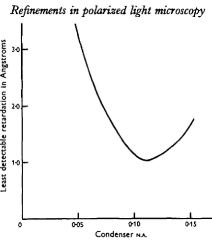
It might be supposed that the greater the extinction factor the better, but in fact there comes a point when any increase in extinction is more than offset by a decrease in contrast sensitivity of the eye. This contrast sensitivity falls off rapidly at the low levels of illumination in the field of the polarizing microscope. Increased extinction necessarily means a reduced level of illumination, and may therefore result in a decreased sensitivity. In practice, however, it is not difficult to strike a balance between these two conflicting effects by slight adjustments to the condenser iris. This effect is shown in Text-fig. 4, where the maximum sensitivity is at a N.A. of O-II.
233
s»
00 <
2-0
1-0
O05 O10
Condenser N A
0-15
[image:8.451.115.331.57.305.2]Text-fig. 4. Effect of condenser N.A. on sensitivity.
Table 1. Approximate values of intrinsic brilliance of various light sources, in candlesjan}
High-intensity carbon arc Low-intensity carbon arc 500 W. high-pressure mercury arc 250 W. high-pressure mercury arc Pointolite
Tungsten filament
100,000 20,000 20,000 10,000 5,000 1000-2000
We have used a 500 W. mercury arc, as well as high- and low-intensity carbon arcs, and found them all satisfactory. The advantage that these sources give over a tungsten filament lamp or a Pointolite can be seen from Text-fig. 5. Strong light sources are also desirable when taking photographs. Though they do not, of course, increase the contrast sensitivity of the film, they do make it possible to use reasonably short exposures.
The second way of achieving a high level of illumination is by using a low magnifi-cation. The desirability of using low-power objectives has already been mentioned in connexion with reducing internal reflexion and eliminating change of plane of polarization; it is also desirable here, for halving the magnification will, of course, quadruple the level of illumination.
(4) The result of applying all the improvements
detectable retardation was measured by eye, using different light sources, with and without a compensator. The results are shown in Text-fig. 5. These curves show clearly the advantages of using a compensator and strong light sources. They show also that the limit of detectability for such an object is about 0-28 A. or 1/20,000th of the mean wave-length of white light. The limit with a more typical biological object is probably about 0-5 A.
- W i t h o u t compensator
- W i t h compensator
Z 05
3 o<
-1
0 3
0-2
I I I I I I I I 1 I 1 t I
10J
i 10* i 10s
I t t t
Tungsten filament Polntollte L L carbon arc H I carbon arc Field brightness in candles/cm.
Text-fig. 5. Effect of level of illumination on least detectable retardation.
MEASURING EXTREMELY SMALL RETARDATIONS
The normal method of measuring small retardations, by using a compensator to obtain a position of maximum blackness of the object or equal intensity of the object and background, is not much use for the very small retardations in a cell. The objects themselves tend to be too small and dim to judge the positions with any accuracy, and they are usually not uniform, but varying rapidly in retardation from point to point. Furthermore, if the cell is living, the retardations may vary rapidly in time.
larger photographs would need impossibly long exposures. For the same reason we have nearly always used the fastest emulsions; either Kodak Super XX or Kodak R55, which is nearly as fast as Super XX and has a much higher contrast. On the same strip of film as the photographs of the object to be measured, it is necessary to include a calibration. This is most easily done by taking a number of photographs of a blank field, with varying amounts of compensation. From such a set of negatives, a curve can be constructed relating the density of the film to retardation. Calibration can alternatively be based on the characteristic curve of the film and the retardation calculated, bearing in mind that the object brightness is proportional to the square of the object retardation. The characteristic curve of the film must, of course, be worked out for the particular conditions. When working out the retardation by either method it is essential to remember that photographs are normally taken with a compensator in position, and to allow for this.
H
Text-fig. 6. Diagram of densitometer. A, ribbon filament lamp; B, beam-splitting cover-glass;
C, rotating sector; D, optical wedge; E, beam-combining cover-glass; F, micrometer on
micro-scope moving stage; G, photocell; H, cathode follower; /, amplifier and cathode-ray oscillomicro-scope.
It remains only to describe the method of measuring film density. Since the negatives are small, and a considerable number of readings may be needed on a single one, we have developed an accurate densitometer working on patches of film down to 50[JL square. It consists essentially of a microscope with a mechanical stage and dial gauge carrying the film to be measured, a logarithmic optical wedge, a battery-operated tungsten ribbon light source, a rotating sector plate letting the light alternately through the microscope and the wedge, and suitable lenses and mirrors for bringing the two rays of light on to a single photocell. The photocell is connected to a cathode follower and thence to the amplifiers of a cathode-ray oscilloscope.
Using a fast time-base two lines are produced, which merge when the two beams are exactly balanced. A diagram of the apparatus is given in Text-fig. 6.
It is possible to take several hundred readings an hour with this densitometer, to an accuracy which varies with the density of the film, but is of the order of 1%. In this way retardations can be measured down to the limit of detectability by eye, or even lower. Byway of illustration. PI. 3, fig. 3, shows a human red blood cell ghost, with a maximum retardation of about 4 A. Text-fig. 7 shows an unsmoothed curve
1-0 0 1-0 20
Distance across edge of membrane In microns
Text-fig. 7. Curve of retardation of the red blood cell membrane.
of retardation across the edge of the membrane. From the shape of such curves, it is possible to deduce a considerable amount of information about the thickness and structure of the membrane. PI. 3, figs. 4-6, shows various other objects with low retardations.
SUMMARY
Various measures to increase the sensitivity of the polarizing microscope for visual observation are discussed. These include choice of polarizing apparatus, reducing condenser and objective aperture, reducing lamp iris, blooming lenses, use of mica plate compensators and use of bright light sources. By such means as these it is possible to detect retardations down to 0-28 A., or i/2O,oooth of a wave-length. A photographic method for measuring retardations down to the same limit in small biological objects, is also described.
REFERENCES
BEAR, R. S. & SCHMITT, F. O. (1936). J. Opt. Soc. Amer. a6, 363. HALLIMOND, A. F. (1944). Nature, Lond., 154, 369.
HAUJMOND, A. F. (1949). Manual of the Polarizing Microscope. Messrs Cooke, Troughton and Simrns Ltd., York.
HUGHES, A. F. & SWANN, M. M. (1948). J. Exp. Biol. 25, 45. KONIOSBEROER, J. (1908). Zbl. Mm. p. 729.
KONIOSBEROER, J. (1909). Zbl. Mm. p. 249.
SCHMIDT, W. J. (1934). Polarisationsoptischeanalyse. Abderhalden's Handb. Biol. Arb.Meth. Abt. 5, Teil io, 435.
SCHMIDT, W.J. (1937). Die Doppelbreckung von Karyoplasma, Zytoplasma und Metaplatma. Protopl. Monogr. 11. Berlin.
SCHMIDT, W. J. (1941). Chromotoma, a, 86.
SCHMITT, F. O. (1947). Medical Physics, ed. Glasser, p. 1586. Chicago. SCHMITT, F. O., BEAR, R. S. & PONDER, E. (1936). J. Cell. Comp. Physiol. 9, 89.
EXPLANATION OF PLATE 3
Fig. 1. Sea-urchin egg in late anaphase, photographed at 0-65 N.A. There is good resolution of granules, etc., but little or no sign of birefringence in the asters, x 500.
Fig. 2. Ditto, photographed at 0-28 N.A. There is poorer resolution, but the birefringence of the asters is clearly visible, as a result of cutting out scattered light. Maximum retardation about 5 A.
x 500.
Fig. 3. Red blood cell ghost in glycerine. Maximum retardation about 4 A. x 2500. Fig. 4. Culture of snail amoebocytes. Maximum retardation about 5 A. x 500.
Fig. 5. Emulsion of olive oil in sucrose solution with refractive indices of the two phases equal, stabilized with sodium hydroxide. The birefringence of the monomolecular layer of sodium stearate can be seen at the edge of the oil droplets. Maximum retardation < a A. x 350. Fig. 6. Pellicle of Paramecium. Maximum retardation about 5 A. x 400.