198
©IJRASET: All Rights are Reserved
Structural Comparison of a Commercial Building
by Manual and Software Analysis
George K George1, Elsa Thomas2, Amal Mathew3, Amala Joseph4, Linu Theresa Jose5
1, 2
M. Tech., 3, 4B. Tech, 5Assistent Professor5, Dept. of Civil Engineering, Amal Jyothi College of Engineering, Koovapally, Kottayam, India
Abstract: This Kanjirappally town faces an acute shortage of parking spaces. So inoder to make maximum utilization of the plot available in such a way that all the existing establishments are properly placed along with that we provide additional floors for shops, bank, and conference hall and also provide ample parking spaces. In this project, proposing an effective method for demolishing the existing building and disposal of debris. Then prepare a new plan, design and analyze the commercial building. Initially planning was done and drawings were prepared by using AutoCAD software. The analysis of the structure was done manually as well as by using ETABS software. And both the results were compared. The design process includes the design of simple basic components and members of a building such as slabs, beams, columns and foundations. After comparing the analysis and design results manual analysis get better results than software process. Software design is less economical than manual design. Time for manual analysis is more and which is complex also. For better and economic results manual analysis and design is better.
Keywords: Plan, Design, Manual analysis, ETABS software, Software design
I. INTRODUCTION
Kanjirappally is a taluk headquarters and a town in Kottayam district, National Highway 183 passes through the heart of the town. There exists a public library building named “Sahrudhaya” owned by the Kanjirappally grama panchayath which is to be demolished. The existing building should be demolished because the walls and roofs are disintegrated which poses a major safety concern for the inhabitants and also affects the aesthetics of the building. The life span of similar buildings is 50 years. Now this building is 72 years old. The plot shares its boundary with NH183 and enjoys a strategic location in terms of commercial value. The entire Kanjirappally town suffers from lack of parking facilities which is major concern. So the building has to be demolished and a new building provided with ample parking facilities needs to be provided to take advantage of the strategic position of the plot.
II. SCOPEANDOBJECTIVES
The scope and objective of the project are to construct a new library building with interior facilities and amble parking facilities, to improve the aesthetics and to make proper use of land available. The main objective of this project is to prepare an architectural plan and analyze and design a multi storied building using ETAB. Analysing the structure involves modelling and analysis using ETAB and obtaining the bending moments, axial forces, shear force diagram and deflection pattern. The design involves designing the building components such as slabs, beams, columns, slabs, footings, staircase etc. manually and compare with the results obtained from ETAB. The design methods used in ETAB analysis are Limit State Design conforming to Indian Standard Codes of Practice. From model generation, analysis and design to visualization and result verification, ETAB is the professional’s choice. One need to analyze and design multi storied building for all possible load combinations [dead, live, wind and seismic loads]. ETAB has a very interactive user interface which allows the users to draw the frame and input the load values and dimensions. Then according to the specified criteria assigned it analyses the structure and designs the members with reinforcement details for RCC frames.
III.METHODOLOGYMODELLING AND ANALYSIS OF THE STRUCTURE
The methodology is as described in steps given below.
A. Reconnaissance B. Preliminary survey
C. Plan for demolition and excavation D. Waste management
199
©IJRASET: All Rights are Reserved
F. Structural analysis G. Design
H. Estimation and cost analysis
IV.MODELLINGANDANALYSISOFTHESTRUCTURE
The modelling is described in steps given below.
A. Define geometry
B. Define material property C. Define frame section D. Define slab section E. Defining load patterns F. Define load combination
The modelling and results of structure using ETABS are given below: The 3D model of the structure is shown in Fig1
Fig.1: 3D Model of The Structure
Shear Force Diagram of the Structure is shown in Fig.2
200
©IJRASET: All Rights are Reserved
Bending Moment Diagram of the Structure is shown in Fig.3
.
Fig.3: Bending moment diagram
Fig.4: Design Output Showing Rebar Percentage
The bending moment obtained from ETAB for longitudinal beam F2G2 is 15.841 kNm and the bending moment for cross beam is 75.566 kNm. The bending moment diagram for longitudinal and cross beam is shown in Fig.5 and Fig.6.The shear force obtained from ETAB for longitudinal beam F2G2 is 22.57 kN and for cross beam is 62.26 kN.
Fig.5: BMD of Longitudinal Beam
201
©IJRASET: All Rights are Reserved
V. STRUCTURALANALYSISANDDESIGNOFBUILDING
A. Design of Slabs
A slab is a thin flexural member used in floor and roofs of structure to carry loads, which are usually supported by walls or beams along its edges. Slabs are plate elements forming floor and roof of buildings carrying distributed loads primarily by flexure.
One-way slabs are those in which the length is more than twice the breadth it can be simply supported or continuous over beams. Two-Way Slab, When the slab is supported on four edges and aspect ratio (Ly/Lx) < 2 the slabs are designed as two way slabs. When slabs are supported on four sides, two-way spanning action occurs. Two way slabs when loaded bends in surface along both short and long span directions causing bending moments in both direction.
Bending moment coefficients are obtained from table 26 of IS 456-2000. In slabs M25 grade concrete and Fe415 grade steel are used.
Fig.7: Slab Numbering
202
©IJRASET: All Rights are Reserved
The reinforcement details for the slabs are given below:
Tb 1: The reinforcement details of slab
Panel Name Dimension
Depth Of Span
Short Span Long Span
At Support At Centre At Support At Centre
S1 1.75X1.45
8mmϕ bars @160mm c/c 8mmϕ bars @160mm c/c 8mmϕbars @160mm c/c 8mmϕ bars @160mm c/c
S2 1.75X2.85
8mmϕ bars @160mm c/c 8mmϕ bars @160mm c/c 8mmϕbars @160mm c/c 8mmϕbars @160mm c/c
S3 1.75X2.85
8mmϕbars @160mm c/c 8mmϕbars @160mm c/c 8mmϕbars @160mm c/c 8mmϕbars @160mm c/c
S4 2.85X5.3
8mmϕbars @160mm c/c 8mmϕbars @160mm c/c 8mmϕbars @160mm c/c 8mmϕbars @160mm c/c
S5 5.3X3
8mmϕbars @160mm c/c 8mmϕbars @160mm c/c 8mmϕbars @160mm c/c 8mmϕbars @160mm c/c
S6 5.3X3
8mmϕ
bars @160mm c/c
8mmϕ
bars @160mm c/c
8mmϕ bars @160 mm c/c 8mmϕ bars @160 mm c/c
S9 3.7X 2.85
8mmϕbars @160mm c/c
8mmϕ
bars @160mm c/c
8mmϕ bars @160 mm c/c 8mmϕ bars @160 mm c/c
S10 5.9X 3 8mmϕbars
@160mm c/c
8mmϕ bars @160mm c/c
8mmϕ bars @160 mm c/c 8mmϕ bars @160 mm c/c
S12 1.75X3
8mmϕbars @160mm c/c
8mmϕ bars @160mm c/c
203
[image:6.612.196.420.86.220.2]©IJRASET: All Rights are Reserved
Fig.9: Design Details of One Way Continuous Slab B. Design of beams
A beam is a structural member subjected to a system of external forces at right angles to the axis. Beams are usually provided for supporting slabs and walls or secondary beams. The beam in which steel reinforcement is provided in the tensile zone only is known as singly reinforced beam. In the case of doubly reinforced beam, reinforcement is provided in compression zone also to carry compressive stresses.
The beam size required was decided based on the largest available span. The estimated size was calculated from the provisions provided in code IS 456:2000 Cl22.1.
[image:6.612.194.419.344.445.2]Use M 25 grade concrete and HYSD steel bars of grade Fe- 415
Fig 10: Details for Longitudinal Beam
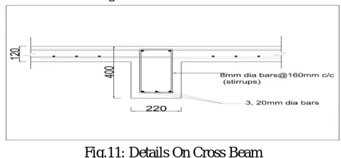
Design of cross beam can be done using Frame analysis
=15 i.e. d= =394 mm.
Take d as 400 mm.
The reinforcement details of cross beam is shown in Fig.11
Fig.11: Details On Cross Beam C. Design of column
A column is an important component of RC structure. A column, in general, may be defined as a member carrying direct axial load which causes compressive stresses of such magnitude .Columns are of two types. A column may be considered as short when the
slenderness ratios and are less than 12.otherwise it is a long column. Design of columns were done using IS 456:2000 and SP
16:1980
[image:6.612.184.425.535.647.2]204
©IJRASET: All Rights are Reserved
The reinforcement detail of column is shown in Fig.12
Fig.12: Details On Column
D. Design of foundations
The foundation of a structure is the part of the structure which transfers the load to the soils on which it rests. It forms a very important part of the structure. The ground surface in contact with lower surface of the foundation is called the base of the foundation. The ground on which the foundation rests is called the subgrade or foundation soil. A foundation should be designed to safely transmit the load of the structure on to a sufficient area of the soil so that the stresses induced in the soil are within the safe limit. If a soil is overstressed, it may lead to a shear failure resulting in the sliding of the soil along a plane of rupture and thus result in the collapse of the structure. Still another point of importance is the need to bring about uniform settlements which should be within the tolerance limits of the superstructure. Due to the load of the structure the soil below is compressed. The settlement of the soil depends on various factors like the intensity of loading, the quality of the soils and depth below the surface level. It is very necessary that the settlement of the various components of a structure should be the same to prevent various secondary stresses. To ensure uniform settlement it is necessary that the foundation area is so provided the intensity of soil reaction is same under all the footings of the structure. Reinforced concrete footing are designed to sustain the applied loads, moments and induced reactions ensuring that the actual bearing pressure does not exceed the safe bearing capacity of the soil. The design is based on the assumption that the function is rigid so that the pressure under the footing will be linear. IS 456:2000 recommends a minimum cover of 50mm for footings.
Fig.13: Reinforcement Details of Foundation
VI.CONCLUSIONS
205
©IJRASET: All Rights are Reserved
building. On the ground floor retail shops are provided. The first floor consists of library, anganvadi and KSLC office. A bank is provided in the second floor and the third floor is a hall which can be used for conducting seminars, functions etc. Design and analysis of building was done manually and using software. Top down approach was used for design. First designed the slab,both one way and two way slabs and sunken slab. Then beam was analysed and designed as longitudinal beam and cross beam. Plinth beam design was also done. Column was designed as short column from the values obtained from e tabs software. Design of square footing and retaining wall were suggested. Also done comparison between manual and Etabs analysis. Etabs anlysis was found to be more economical than manual design from the results. From the manual analysis, basic ideas for design and analysis of building components were obtained. Generally we can say that software approach is more faster. After comparing the analysis and design results manual analysis get better results than software process. Software design is less economical than manual design. Time for manual analysis is more and which is complex also. For better and economic results manual analysis and design is better.
REFERENCES
[1] Achuta Rao.(2012). “Demolition of structures part-II”. IRICEN Journal of Civil Engineering,
[2] Hemalatha B.R., Nagendra Prasad.(2008). “Construction and demolition waste recycling for sustainable growth and development”. Journal of Environmental Research and Development, 2(4), 759-765.
[3] IS 456 : 2000 . “Code of Practice for Plain and Reinforced Concrete”. Bureau of Indian Standards, New Delhi [4] IS 875 (Part 2) 1987. “Code of Practice for Design Loads” . Bureau of Indian Standards, New Delhi
[5] KMBR rules (2013 & 1999)
[6] Malvia R. K., Kulkarni V. K. (2013). “Building Demolition: Ground to Earth Important as Construction”. International Journal of Emerging Technology and Advanced Engineering, 3(4), 396-400.
[7] N Krishna Raju. “Advanced Reinforced Concrete Design”. Design of concrete structures. [8] Ramamruthum S. “Reinforced Concrete Design” .Design of Reinforced Concrete Structures.