Abstract— In this paper an active modal TMD control logic
for the vibration suppression is presented. Starting from the traditional TMD theory, a closed loop formulation is proposed to calculate the active control force. The possibility to describe every mechanical systems or civil structures with a set of modal coordinates allows to act independently on each d.o.f. The technique is compared with different solutions already present in literature, such as the IMSC and the PPF. Numerical simulations, based on a FEM linear model, are carried out to investigate the pro and con of each logic.
Index Terms— Active modal TMD, resonant control, vibration suppression
I. INTRODUCTION
The necessity to reduce the vibrations in the structures has always played a fundamental role not only in mechanics but also in many civil/architectonic applications. The stresses associated to the dynamic amplifications acting on these structures, in particular when they are forced in nearly resonance conditions, can affect their performances and integrity. These considerations assume even more importance when the same stresses lead to a component lifetime reduction and, as a consequence, to implications about the safety of persons and things in close contact with the structures under investigation.
For these reasons, the designers generally operated adopting passive devices able to reduce the vibrations level. The most intuitive solution is to apply viscous dampers for the energy dissipation. Anyway this approach implies some limits mainly due to the necessity of defining a fixed point to set to the ground the viscous forces. Moreover, the same fixed point becomes a critical element in the optimization procedure of damper parameters, since it actually modifies the dynamic response of the system. A solution to these limits has been reached thanks to the introduction of the mass damper theory. Thanks to its simplicity, although well
Manuscript received March 05, 2011; revised April 12, 2011
G. Cazzulani is with the Mechanical Engineering Department of Politercnico di Milano, Milan, ITALY (corresponding author to provide phone: 0039-02-2399-8430; fax: 0039-02-2399-8492; e-mail: [email protected]).
G. Resta is with the Mechanical Engineering Department of Politercnico di Milano, Milan, ITALY (e-mail: ferruccio.resta@ polimi.it).
F. Ripamonti is with the Mechanical Engineering Department of Politercnico di Milano, Milan, ITALY (e-mail: francesco.ripamonti@ polimi.it).
known for many years, also this passive device is still widely adopted in many civil and mechanical systems [1-4]. The working principle, based on the synchronization between the natural frequency an of an auxiliary single d.o.f. coupled system and one of the original structure (from which the name “Tuned Mass Damper”, TMD), involves that it operates applying an inertial force 90 degrees out of phase with respect to the displacement. The main limit of this device is the ability to protect the system for a given range of frequencies, while the others are practically uncontrolled. During the years, to improve their performances multiple resonances TMD have been created, as e.g. the Stockbridge [5], for the vibrations suppression in the cables of high voltage energy transmission lines, able to operate in a wider frequency range.
Anyway during the last decades, thanks to the improvements and the cost reduction of calculators and actuators systems, besides the passive devices also the active ones have assumed more importance. In dynamic applications particularly interesting are the solutions classified as active modal controls, able to independently act on each generic structure vibration mode. In this sense each vibration mode of the system under investigation can be analyzed as a single d.o.f. system. In general all the active control logics for vibrations suppression are based on several steps, summarizing as:
- Identification of the system vibratory state by means of modal filters or observers [6,7];
- Definition of the control law that, starting from the vibration level, returns the damping force;
- Actuation of the control forces through a suitable actuators system (piezoelectric, magneto-strictive, inertial electromechanical,…) [8];
- Evaluation of possible undesired effects associated to the implementation of the logic on a real system (for example spillover) [7,9].
The aim of present work is to investigate the second point, comparing different control logics and evaluating pro and con. Firstly two known-in-literature logics, the Independent Modal Space Control (IMSC) [10,11] and the Positive Position Feedback (PPF) [12,13], are briefly presented. Then an active TMD logic is proposed. Starting from the traditional TMD theory, it adopts a modal approach to calculate the control force, overcoming some of the TMD typical limits such as the imposed ratio between the system and the auxiliary masses, the static deflection due to the auxiliary mass,… Finally the different solutions have
The Active Modal Tuned Mass Damper
(AMTMD)
for Vibration Suppression in Flexible Structures
been tested by means of numerical simulations on a linear system.
II. STATEOFTHEARTSOLUTIONS Consider a generic linear mechanical system
[ ] [ ] [ ]
M x+ R x+ K x f= c+fd (1)where
- x is the vector containing the n independent coordinates
-
[ ]
M and[ ]
K respectively represent the inertial and elastic matrices;-
[ ]
R is the damping matrix, assumed to be proportional to the elastic and inertial ones;- fc is the vector containing control contribution, while d
f represents the generic disturbance forces applied to the system.
For a complex system (such as beam, plate, etc.), these matrices come from a discretization of the structure, for example using the Finite Element Method (FEM). For this reason they can be very large and un-useful for the synthesis of the control law. In this case modal approach is very attractive, because it allows to describe the system through a limited set of modal coordinates. In fact, higher modes are typically very damped and difficult to excite and can be neglected in the control formulation. Defining
[
Φtot]
then n× eigenvector matrix of
[ ] [ ]
M −1 K , the following coordinate change can be performed[
tot]
tot =x Φ q (2)
where
tot
q is an n vector containing all the system modal coordinates. Considering only the first m modes, the (2) becomes
[ ]
x Φ q (3)
where
[ ]
Φ is an n m× matrix containing only the considered modal shapes. Substituting the (3) in the (1), a series of decoupled modal equations can be obtained as, ,
i i i i i i c i d i
m q +r q +k q =u + f (4)
where the subscript "i" indicates the i-th modal equation. Therefore, through the (4), it is possible to define the control law uc i, independently for each mode. For this
reason, in the following, a single-mode system is considered to describe the different control laws proposed.
In particular in this section a brief overview of some important control theories developed in modal approach in the last decades is presented. Two strategies, Independent Modal Space Control (IMSC) and Positive Position Feedback (PPF) are investigated.
A. Independent Modal Space Control
Considering the (4), the aim of the IMSC is to modify independently the dynamic behaviour (natural frequency and damping) of each controlled mode, without changing the parameters of the uncontrolled ones. The modal control force uc i, is defined as
, , ,
c i v i i p i i
u = −g q −g q (5)
and the closed loop equation of motion becomes
(
,)
(
,)
,i i i v i i i p i i d i
m q + r+g q + k +g q = f (6)
The two parameters gp i, and gv i, allow to set
respectively the natural frequency and the damping ratio of the i-th controlled mode. In mechanical field, especially considering a vibration control problem, the position gain
,
p i
g is often set to zero in order to avoid higher control forces and mechanical stress of the structure.
B. Positive Position Feedback
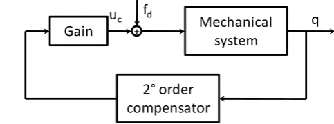
Another control strategy is the Positive Position Feedback (PPF), introduced by Goh and Caughey in 1985. In this method, the feedback control force is provided by a 2nd order compensator (fig. 1).
Mechanical system
2° order compensator
q uc fd
+
[image:2.595.311.553.440.530.2]Gain
Fig. 1. Scheme of PPF controller for a single mode
Dividing the (4) by mi
2
, ,
2 c i
i i i i i i d i
q+ ξ ωq +ω q =u + f (7)
the control law can be defined as
2 ,
c i i f i
u =gω η (8)
where ηi is calculated through the 2nd order
compensator defined by
2 2
2
i f f i f i fqi
η + ξ ω η ω η + =ω (9)
In this formulation ξi and ωi represent the damping ratio
and natural frequency of the i-th mode, while ξf and ωf
(9), the equation of the closed loop system can be obtained as
2 2
,
2 2
2 0
0 2
0
i i
i i
f f
i i
i
i i f d i
i
f f
q q
q
g f
ξ ω ξ ω
η η
ω ω
η
ω ω
⎡ ⎤
⎧ ⎫ ⎧ ⎫
+
⎨ ⎬ ⎢ ⎥⎨ ⎬
⎩ ⎭ ⎣ ⎦⎩ ⎭
⎡ − ⎤⎧ ⎫ ⎪⎧ ⎫⎪
+⎢− ⎥ ⎨ ⎬ ⎨= ⎬
⎪ ⎪
⎢ ⎥ ⎩ ⎭ ⎩ ⎭
⎣ ⎦
(10)
The closed-loop system is stable if the stiffness matrix is positive-definite. This condition is verified if and only if
2
2
i i
f
g ω
ω
< (11)
III. ACTIVETUNEDMASSDAMPER
In this article, a control formulation combining the benefits in controlling independently the system modes with the know-how of the well known tuned mass damper theory is proposed. For this reason, for the sake of completeness, the traditional TMD for a mechanical system is presented. Subsequently this formulation is extended to a generic multi-modal case, considering an independent modal TMD control force.
A. Traditional TMD
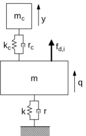
Considering a generic single degree of freedom system, the classical tuned mass damper (TMD) consists of a mass-spring-damper system connected to the system (fig. 2).
m mc
r k
rc kc
y
[image:3.595.127.216.431.571.2]q fd,i
Fig. 2. A single degree of freedom system with TMD
Calling mc, rc and kc the mass, damping and stiffness of
the TMD, the equation of motion of the complete system becomes
,
0 0
0
c c
c c c
c c d i
c c
m q r r r q
m y r r y
k k k q f
k k y
+ −
⎡ ⎤⎧ ⎫ ⎡ ⎤⎧ ⎫
+
⎨ ⎬ ⎨ ⎬
⎢ ⎥ ⎢ − ⎥
⎩ ⎭ ⎩ ⎭
⎣ ⎦ ⎣ ⎦
+ −
⎡ ⎤ ⎧ ⎫ ⎧ ⎫
+⎢ ⎥⎨ ⎬ ⎨= ⎬
− ⎩ ⎭ ⎩ ⎭
⎣ ⎦
(12)
Usually mc is chosen between 5% and 10% of the system
mass m, while kc is tuned so that k mc c =k m and rc is
dimensioned in order to maximize the damping effect around the system resonance.
B. Modal Active TMD
As in the PPF technique (fig 1), it is possible to design a 2nd order compensator providing on the system a force calculated with the TMD equation. Considering the equation of the generic i-th mode (4), the active modal TMD compensator (AMTMD) can be designed as
(
)
(
)
, , ,
c i c i i i c i i i
u =k y −q +r y −q (13)
where
, , , , ,
c i i c i i c i i c i i c i i
m y +r y +k y =k q +r q (14)
Under the assumption of knowing exactly the modal coordinate qi of the system, the closed-loop is stable for
any value of the parameters mc i,, rc i, and kc i, . Anyway, in
order to achieve the best performances, their values should be chosen using the same approach, for each considered mode, of the single degree of freedom TMD, optimizing the phase between control force and displacement.
C. Extension to a multi-modal system
Until now, for every proposed method, the single modal coordinate has been considered under the assumption that it can be directly measured and controlled. The so-calculated forces uc i, represent the contributions of the actuator forces on the considered modes. In real cases, as said in the introduction paragraph, when a multi-mode system is considered, it becomes necessary to know the single modal contributions on system vibration and the actuator action on each mode.
Under the assumption of distributed actuators and sensors (for example piezoelectric patches) it's possible to measure directly each considered mode and to act directly on it, applying the previously calculated modal forces [8]. In all the other cases it becomes necessary to link the real forces and measurements with the considered modal contributions. In this case, knowing the generic nm measurements vector
μ, the modal coordinates can be calculated as
[ ][ ]
(
)
1m
− =
q Λ Φ μ (15)
where
(
[ ][ ]
Λm Φ)
is an m n× m matrix linking the modalcoordinates with the measurements. This matrix must be invertible. It means that it must be square (the number of measurements must be equal to the number of considered modes) and nonsingular (the system must be observable). If
m
n <m, modal observers [7] can be used to estimate the modal coordinates of the system.
The actuator forces can be calculated as
[ ] [
]
(
)
1act act
T T
c
− =
F Φ Λ u
the modal action calculated by (13). The nact×m matrix
[ ] [
]
(
act)
T T
Φ Λ must be invertible too. It means that the condition nact =m must be satisfied and the system must be
controllable. If the number of considered modes is greater than the number of actuators, Moore-Penrose pseudo-inverse of
(
[ ] [
ΦT Λact]
T)
can be used but, in this case, the control force couple the system modes.IV. NUMERICALRESULTS
In this section, a numerical analysis is performed to compare the proposed control strategies. The FEM numerical model of a clamped beam is considered (Fig. 3).
fd Fact1 Fact2 Fact3
[image:4.595.332.523.55.370.2]1 2 3
Fig. 3. The beam model considered for the numerical simulations
Table 1 resumes the main properties of the beam, while Table 2 shows the position of sensors and actuators.
TABLEI
CHARACTERISTICS OF THE CLAMPED BEAM
Length 1 m
Section 4E-4 m2 J 3.3E-7
E 70 GPa
TABLEII
POSITION OF SENSORS AND ACTUATORS WITH RESPECT TO THE CLAMP
Actuator Position [m] Sensor Position [m] 1 0.38 1 0.31 2 0.63 2 0.50 3 0.69 3 1.0 At first a comparison between the performances of IMSC and PPF on this system will be presented. In order to control the system modes independently, a 3-modes controller is implemented. In this way, the matrices of the (15) and (16) can be inverted. The control strategies performances are evaluated through the transfer function between the beam tip displacement and a vertical disturbance force, applied at 0.125 m from the clamp (fig. 3).
100 101 102 103
10-9 10-8 10-7 10-6 10-5 10-4 10-3
Frequency [Hz]
T
ra
ns
fer
f
u
nc
ti
o
n m
odu
lus
[
dB
]
No control PPF control
100 101 102 103
10-9 10-8 10-7 10-6 10-5 10-4 10-3
Frequency [Hz]
T
ra
ns
fer
f
u
nc
ti
o
n m
odu
lus
[
dB
]
No control IMSC control
(a)
(b)
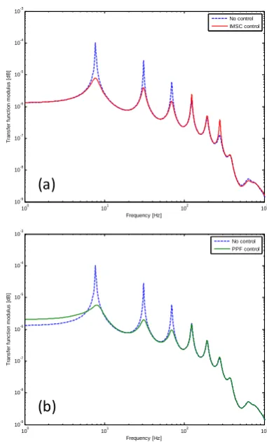
Fig. 4. Comparison between the transfer function of the uncontrolled system with IMSC (a) and PPF (b)
Figure 4 shows the comparison between IMSC and PPF. It can be noticed that, considering only the modeled modes, the damping effect introduced by the IMSC is greater than the damping effect of PPF (from a theoretical point of view, under the assumption of ideal actuators, there is no limit to the increase of damping introduced on the modeled modes). Besides PPF worsens the system response in the quasi-static range of frequencies (below the first system resonance).
The great advantage of PPF is that the feedback loop is represented by a low-pass filter. For this reason, as shown in the pole diagram in fig. 5, the spillover risk on higher modes is lower. In particular, for this application, IMSC causes an important spillover effect on the sixth mode (about 300 rad/s), while using PPF control this effect is greatly reduced.
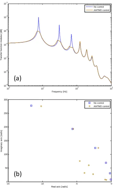
The AMTMD control is able to achieve the same performances of PPF in terms of effectiveness around the resonances and spillover rejection, but without causing the quasi-static amplification typical of the PPF. Figure 6 shows the transfer function between tip displacement and disturbance force using AMTMD control (see, for comparison, fig. 4 and 5).
[image:4.595.58.290.244.321.2]
-15 -10 -5 0
0 50 100 150 200 250 300
Real axis [rad/s]
Im
a
g
in
a
ry
a
x
is
[r
a
d
/s
]
No control PPF control
-15 -10 -5 0
0 50 100 150 200 250 300
Real axis [rad/s]
Im
a
g
in
a
ry
a
x
is
[r
a
d
/s
]
No control IMSC control
(a)
[image:5.595.73.262.57.369.2](b)
Fig. 5. Comparison between the poles of the uncontrolled system with IMSC (a) and PPF (b)
-15 -10 -5 0
0 50 100 150 200 250 300
Real axis [rad/s]
Im
agi
na
ry
a
x
is
[
rad
/s
]
No control AMTMD control
100 101 102 103
10-9 10-8 10-7 10-6 10-5 10-4 10-3
Frequency [Hz]
T
ra
ns
fer
f
u
nc
ti
o
n m
odu
lus
[
dB
]
No control AMTMD control
(a)
(b)
Fig. 6. Transfer function (a) and poles diagram (b) of the system controlled with AMTMD
V. CONCLUSIONS
The paper proposes a control strategy that merges the independent control of system modes (as IMSC) and the know-how of the tuned mass dampers. The result is an active control method, that has been called "Active Modal Tuned Mass Damper (AMTMD)", that achieves the same performances of Positive Position Feedback (PPF) around the resonances, without increasing the low frequency response.
An experimental campaign will be carried out in order to validate the proposed control strategy on real applications.
REFERENCES
[1] R. Rana and T.T. Soong (1998). Parametric study and simplified
design of tuned mass dampers. Engineering Structures, Volume 20(3), pp. 193-204
[2] Y.L. Xu and B. Samali and K.C.S. Kwok (1992). Control of along
wind response of structures by mass and liquid dampers. Journal of Engineering Mechanics, Volume 118(1), pp. 20-39
[3] T. Igusa and K. Xu (1994). Vibration control using multiple tuned
mass dampers. Journal of Sound and Vibration, Volume 175(4), pp. 491-503
[4] C. Li (2000). Performance of multiple tuned mass dampers for
attenuating undesiderable oscillations of structures under the ground acceleration. Earthquake Engineering and Structural Dynamics, Volume 29(9), pp. 1405-1421
[5] D. Sauter and P. Hagedom (2002). On the hysteresis of wire cables in
stockbridge dampers. International Journal of Non-Linear Mechanics, Volume 37(8), pp. 1453-1459
[6] L. Meirovitch and H. Baruh (1985). Implementation of modal filters
for control of structures. Journal of Guidance, Control and Dynamics, Volume 8(6), pp. 707-716
[7] F. Resta and F. Ripamonti and G. Cazzulani and M. Ferrari (2010).
Independent modal control for nonlinear flexible structures: An experimental test rig. Journal of Sound and Vibration, Volume 329(8), pp. 961-972
[8] C.K. Lee and F.C. Moon (1990). Modal sensors/actuators. Journal of
Applied Mechanics, Transaction ASME, Volume 180, pp. 434-411
[9] M.H. Kim and D.J. Inman (2001). Reduction of observation spillover
in vibration suppression using a sliding mode observer. Journal of Vibration and Control, Volume 7(7), pp. 1087-1105
[10] M.J. Balas (1978). Active control of flexible systems. Journal of
Optimization Theory and Application, Volume 25(3), pp. 415-436
[11] L. Meirovitch and H. Baruh (1983). Robustness of the independent
modal-space control method. Journal of Guidance, Control and Dynamics, Volume 6(1), pp. 20-25
[12] C.J. Goh and T.K. Caughey (1985). On the stability problem caused
by finite actuator dynamics in the collocated control of large space structures. International Journal of Control, Volume 41(3), pp. 787-802
[13] D.J. Inman (2001). Active modal control for smart structures.
[image:5.595.73.261.427.738.2]