©IJRASET: All Rights are Reserved
881
Design and Fabrication of Industrial Gearbox for
Magneto Test Rig
Akash R. Mitra1, Ankita M. Patil2, Arjun S. Gopinath3, Chaitali V. Belekar4, V P. Kulkarni5
1, 2, 3, 4, 5
Mechanical Engineering Department, MIT Academy of Engineering, Pune
Abstract: A magneto is an electrical generator used in several commercial vehicles for providing valuable current for various operations. A thorough and very well designed testing process is necessary to pass the application of such a device for commercial application. This report focuses on the design, development, and fabrication of a single speed gearbox required for the successful testing operation of the magneto test rig. This results in a fully optimized and well-functioning gearbox to satisfy the testing requirements, to develop a fully tested and proper functioning magneto. The gearbox can be used for operating speeds up to 15,000 rpm.
Keywords: Magneto, gearbox, commercial application, design, fabrication.
I. INTRODUCTION
A proper functioning and efficient magneto in an automobile, can result in a substantial amount of energy conservation for various processes. As a result, magnetos are used widely as ignition systems in various appliances and machines like small lawn movers, motor bikes, mopeds, airplanes, etc. During the testing phase of a magneto, it needs to be tested at a maximum speed of 15,000 rpm. To achieve such high speeds, a gearbox has to be designed which converts the output speed from an input motor to the desired output speed which will be fed to the magneto. A well designed and fabricated gearbox, which does the necessary job of producing the high speeds with minimal maintenance, has the tendency to carry out the testing process smoothly and efficiently. The gearbox needs to function for a significant period of time without replacement of major components or major maintenance requirements to optimise time consumption, which is a very important aspect in commercial industries. A typical industrial gearbox should not have high operational sound and should also be easy to service and transport. The basic types of gearboxes use helical gear pairs because of their quite operation and high efficiency.
II. DESIGNPROCESS
A. Design Procedure
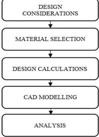
[image:1.612.224.384.495.716.2]The design process for the industrial gearbox of the magneto test rig is classified into various steps as mentioned in figure 1.
©IJRASET: All Rights are Reserved
882
B. Design ConsiderationsIn order to reach to the required output point, precise design considerations have to be made to ensure accurate design of the component. Some of the design considerations for the design of the industrial gearbox are listed below:
1) Available input rpm and the required output rpm define the domain of operation for the gearbox.
2) Ease of serviceability and maintenance as and when required.
3) Quiet and smooth operation.
4) Sufficient life of OEM components to ensure economic efficiency.
5) Appropriate material selection considering availability and budget allowances.
6) Factor of Safety (FOS) of manufactured components.
C. Material Selection
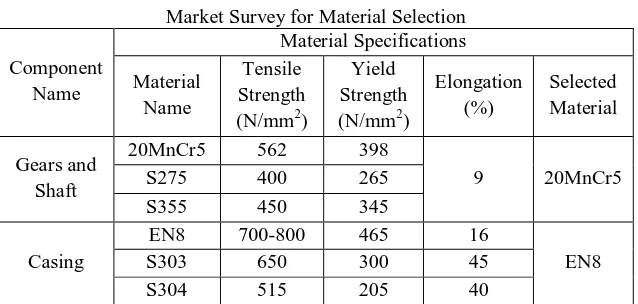
[image:2.612.148.467.304.456.2]The various components that have to be manufactured in-house like gears, shafts, gearbox casing should have sufficient strength and other physical properties to ensure they reach their calculated potential. In order to fulfil these design requirements, proper materials have to be used to manufacture these components. A detailed market survey was carried out to jot down the advantages and limitations of various materials so as to arrive at a fixed conclusion. The materials selected as per components have been represented in table I.
TABLE I
Market Survey for Material Selection
Component Name Material Specifications Material Name Tensile Strength (N/mm2)
Yield Strength (N/mm2)
Elongation (%) Selected Material Gears and Shaft
20MnCr5 562 398
9 20MnCr5 S275 400 265
S355 450 345
Casing
EN8 700-800 465 16
EN8 S303 650 300 45
S304 515 205 40
D. Design Calculation
The calculations for the input, output and lubrication shafts have been carried out using the shear force and bending moment diagrams. The forces acting at the various points on the shaft can be obtained by calculating the tangential, radial and axial forces acting on the gears. For the input shaft, the forces on the spur pinion and helical gear have to calculated and applied on the shear force and bending moment diagrams. For the output shaft, the forces on the helical pinion have to be calculated and applied to the shear force and bending moment diagrams. And as for the lubricating shaft, the spur gear’s forces have to be calculated and applied. The preliminary estimation and precise estimation by Buckingham’s equation has been used for the calculation of dimensions and forces of the gears.
The final selected module was 2 for spur gear pair and 1 for the helical gear pair. The gear ratio is 5:1 to achieve the output speed of 15,000 rpm from the input speed of 3,000 rpm from the selected motor. The Factor of Safety (FOS) has been considered as 2 to avoid both bending and pitting failure. For the gear calculations,
Preliminary estimation, V = (π x dp xnp)/60,000
dp = mt x Zp = (mn x Zp)/cos ϕ
Velocity factor, (for v < 30) Kv = 5.6/(5.6 + √v)
Load distribution factor, (for face width upto 50 mm) Km = 1.2
©IJRASET: All Rights are Reserved
883
Tangential force, Ft = P/V
Effective load, Feff = (Ka x Km x Ft)/Kv
OS = 2 FOS = Fb/Feff
Therefore, dp = mt x Zp
dg = mt xZg
Precise estimation, e = 8 + 0.63 (mn +0.25 √d)
e = ep + eg
Fd = {21 x V [b x c x cos2 ψ + Ftmax] x cos ψ}/{(21 x V) + √b x c x cos2ψ + Ftmax}
Feff = Ka x Km x Ft + Fd
FOS = Fb/Feff
Ft = T/(d/2)
Fr = Ft x tan ϕ
Fa = Ft x tan ψ
III.MANUFACTURINGPROCESS
After the design and analysis of the various components, their physical realization is the next step. This can be achieved by carefully selecting the manufacturing processes to achieve accurate and cost efficient results. As for OEM components, a detailed survey considering various important factors is carried out to determine their compatibility and functionality. The manufacturing procedure from raw material to finish product for the different components is mentioned below.
A. Gears and Shafts
There are 3 integrated shafts with gears machined on them and 1 individual gear which will be splined to the shaft.
1) Raw material procurement considering appropriate machining tolerances
2) Turning, facing and taper turning on conventional lathe machine of gear blank and shaft
3) Gear cutting according to design parameters
4) Gear hardening followed by teeth grinding to achieve high accuracy
5) Cylindrical grinding of shaft to achieve designed inside diameter
6) Micro grinding to achieve bearing surface finish on shaft
B. Gearbox Casing
1) Raw material procurement considering appropriate machining clearances and mechanical properties
2) Preparation of mould for casting
3) Casting of gearbox casing
4) Finishing (milling and drilling) on CNC
C. Spindle
1) Raw material procurement considering appropriate clearances
2) Turning and facing on conventional lathe machine
3) Cylindrical grinding to achieve desired diameter and fit
4) Micro grinding for bearing surfaces
D. Coupling
1) Raw material procurement
2) Turning and facing on conventional lathe machine
©IJRASET: All Rights are Reserved
884
IV.CADMODELLINGANDANALYSIS
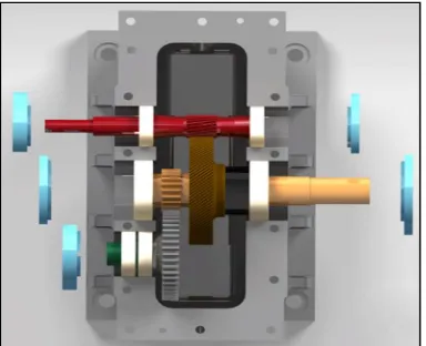
[image:4.612.202.394.153.309.2]After the theoretical calculations and considerations of gears, shafts and gearbox casing, their design and analysis is mandatory to achieve the desired output. The design process is iterative in nature considering various factors like, budget constraints, space constraints, strength, weight, etc. Every design is analysed for potential modes for failure and these modes of failure are minimised to the maximum possible extent. The final designs are as follows:
[image:4.612.196.420.343.503.2]Fig. 1 Cross-sectional view of gearbox depicting input (orange), output (red) and lubricating (green) shafts
Fig. 2 Assembled gearbox
The various analysis carried out were static structural analysis of the gears and shafts, and modal analysis of the gearbox casing.
[image:4.612.134.486.547.714.2]©IJRASET: All Rights are Reserved
885
V. CONCLUSIONS
The required gearbox with optimized performance and weight has been manufactured considering essential parameters to reduce cost of manufacturing and also ease of serviceability and maintenance. This kind of industrial gearbox, has various applications in the heavy machinery industry and can be operated at speeds of upto 15,000 rpm without any significant failure or hamper in performance.Thus we can conclude that the Magneto mounted for testing would survive at extreme natural conditions and climatic changes, making it suitable to be assembled in the vehicle.
REFERENCES
[1] International Journal of Advance Engineering and Research Development (IJAERD) Volume 5, Issue 04, April-2018, e-ISSN: 2348 - 4470, print-ISSN: 2348-6406
[2] SKF bearing' [ online ].Available - https://www.google.com/url?sa=t&source=web&rct=j&url=https://www.skf.com/binary/21-121486/Rolling-bearings. [3] Automobile engineering - Kripal Singh
[4] Milosav Ognjanovic1 – Miroslav Milutinovic2, (2012), Design for Reliability Based Methodology For Automotive Gearbox Load Capacity Identification”, Journal of Mechanical Engineering, Vol. 59 (5), pp. 311-322.
[5] Simple Discussion on Stepper Motors for the Development of Electronic Device - Tanu Shree Roy, Humayun Kabir, Md A. Mannan Chowdhury (International Journal of Scientific & Engineering Research, Volume 5, Issue
[6] Design Analysis Of Industrial Gear Box Casing-Balasaheb Sahebrao Vikhe (IRJET) e-ISSN: 2395 -0056 Volume: 03 Issue: 11
[7] Research Paper On Gearbox Failure Analysis - Sandip Rathva, Sohail Siddiqi ( International Journal Of Advance Engineering And Research Development
Volume 5, Issue 04)
[8] Design And Analysis Of Gear-Box Using SpurGear And Eliminating The Differential Unit - Rahi Jain And Pratik Goyal (Ijmet)Volume 7, Issue 6
[9] Design For Reliability Based Methodology For Automotive Gearbox Load Capacity Identification - Milosav Ognjanovic1 – Miroslav Milutinovic2,
(Strojniški Vestnik - Journal Of Mechanical Engineering 59(2013)5, 311-322 Received For Review: 2012-05-21
[10] Analysis & Optimization of Gearbox Efficiency - Parth B. Shah Chandresh Motka(IJIRST –International Journal for Innovative Research in Science & Technology| Volume 1 | Issue 8 )