Abstract— In high-speed milling (HSM) of the hardened steels, the reduced tool life has always been a concerning issue. Moreover, in the case of finish HSM, the requirement of minimizing the workpiece surface roughness also gains considerable importance. In this research work, series of experiments were conducted in order to quantify the effects of three cutting parameters – namely: cutting speed; feed rate; and radial depth of cut – upon tool life and surface roughness. In total, 16 experiments were conducted following Central Composite Rotational Design (CCRD) Method. The machining of AISI D2 (~62HRc) was performed using TiAlN coated carbide cutters, under MQL environment. The experimental data were used to develop empirical models for determining performance measures. Application of MQL was proved beneficial for enhancement of tool life. SEM photographs and EDS analyses revealed that chipping and adhesion were the dominant tool damage mechanisms in majority of the experiments.
Index Empirical modeling, tool life, hardened steels, MQL, surface roughness
I. INTRODUCTION
fter the advent of high-speed milling (HSM) technology, it was quickly applied to the cutting of steels in their hardened states, and the process was named as ‘Hard-Milling’. The hard-milling process offered numerous advantages like attainment of workpiece compressive residual stresses, reduction in workpiece micro-structure alterations, elimination of surface micro-hardness increases, and improvement in fatigue life besides other benefits of HSM like reduction of lead time and cutting forces [1
–
4]. On the other hand the hard milling process comes also with a major demerit of reduced tool life. The useful life of cutting tool is drastically reduced when it is applied to machining of hardened steels, especially, in the high-speed range [5]. The higher the hardness of the workpiece material, the lower is the life of the cutter [6]. Finding the ways for enhancement of tool life in the hardManuscript received December 20, 2010; revised December 27, 2010. A. Iqbal is with Department of Mechanical Engineering, Eastern Mediterranean University, Gazimagusa, TRNC, via Mersin 10, Turkey (+90-533-881-7427; fax: +90-392-365-3715; e-mail: [email protected]).
N. He was with College of Electrical & Mechanical Engineering, Nanjing University of Aeronautics and Astronautics, Nanjing 210016, P.R. China (e-mail: [email protected]).
L. Li is with College of Electrical & Mechanical Engineering, Nanjing University of Aeronautics and Astronautics, Nanjing 210016, P.R. China (e-mail: [email protected]).
milling domain is a hot topic of research these days. Moreover, in the case of finish hard-milling, the objective of ‘minimizing workpiece surface roughness’ also gains considerable importance.
From the previous research work, in which the hard-milling experiments were performed mostly in dry condition, it can be concluded that the cutting speed is the most influential cutting parameter upon tool life. Higher values of this parameter, as well as of feed rate and depths of cut have proved to be detrimental for tool life [3, 5, 7, 8, 9]. For the case of workpiece surface roughness, the most influential cutting parameter has been reported as feed rate, followed by cutting speed and depths of cut [10]. Some opposing observations have been reported related to the effects of cutting speed and feed rate upon workpiece surface roughness [3, 6, 11].
Machining with minimum quantity of lubrication (MQL) can cut down cost and improve both tool life and surface finish [12]. MQL is the name given to the process in which very small amount of oil (less than 30ml/hr) is pulverized into the flow of compressed air [13]. The air/oil aerosol mixture is then fed to the cutting area through the ducts.
In the current research work, the effects of three cutting parameters – namely cutting speed (Vc), feed rate (fz), and radial depth of cut (ae) – have been experimentally sought upon three performance measures – namely: tool life; arithmetic average surface roughness, measured along the direction of feed (Ra(along)); and arithmetic average surface roughness, measured across the direction of feed (Ra
(across)) – in high-speed end milling of hardened AISI D2, using coated carbide cutters, under MQL environment.
II.EXPERIMENTAL WORK
The experiments were performed on Micron UCP 710, 5-axis, vertical milling center having maximum power of 16kW. Flank wear of tools was measured using 10x tool maker’s microscope and the surface roughness was measured using Mahr Perthometer M1. SEM (Scanning Electron Microscope) pictures of all the tools were taken using Joel JSM 5610LV microscope, while Thermo Noran Energy Dispersive Spectrometer along with Vantage digital acquisition engine were used to conduct EDS (Energy Dispersive Spectrometry) analyses at the surfaces of the tools.
Empirical Modeling the Effects of Cutting
Parameters in High-Speed End Milling of
Hardened AISI D2 under MQL Environment
Asif Iqbal, Ning He, Liang Li
TABLE I
MAXIMUM AND MINIMUM SETTINGS OF PREDICTOR VARIABLES
Level Vc(m/min) fz(mm/tooth) ae(mm)
Minimum 175 0.08 0.15
Maximum 275 0.12 0.4
A. DoE and tooling parameters
A full factorial, Central Composite Rotational Design (CCRD) Method was utilized for the design of experiments. See details of CCRD in [14]. A total of sixteen finish hard-milling experiments were performed out of which eight represented regular points, two represented central points, and the remaining six represented star points (or axial points), utilizing the alpha value of 1.68179. Three predictor variables (parameters) were tested in the experiments: cutting speed (Vc), feed rate (fz), and radial depth of cut (ae). Table I presents the maximum and minimum settings of these predictor variables. Three response variables were observed: tool life, measured in mm2 of area of material removed; arithmetic surface roughness – in microns – averaged upon the machined length of workpiece (a) along direction of feed (Ra(along)); and (b) across the direction of feed (Ra(across)).
In all the experiments fixed tooling parameters were utilized. The cutting tools used were flat end solid K30 carbide cutters with PVD coated mono layer of TiAlN, having diameter (D) of 8mm, corner radius (R) of 1.5mm,
helix angle (λ) of 55º, rake angle (γ) of -8º, flank angle (α) of 6º (primary) and 10º (secondary), and number of flutes (Z) equal to 4. The workpiece material utilized was hardened AISI D2 (hardness 62 ~ 63HRc; and workpiece dimensions 50mm × 60mm × 66mm).
The MQL, consisting of UNILUB2032 – a high performance metal cutting lubricant – pulverized into compressed air of 6bars, at a rate of 25ml/hr, was applied directly to the tool using two aerosol ducts arranged at 160º apart. Axial depth of cut (ap) was kept 4mm for all the
experiments and down-milling was employed as milling orientation. The overhang of tool was fixed to 28mm and its radial run-out was maintained <10μm. The milling was
performed in straight line and length of each pass was 60mm. Tool failure criterion used, was the maximum width of flank wear land (VBmax) of 0.2mm.
III. ANOVA, REGRESSION,AND OPTIMIZATION
Table II presents the tool life and surface roughness results for the sixteen experiments. Only the tool used in experiment number 14 could not complete the run as it was shattered into three pieces when it had removed 2220mm3 (4mm × 555mm2) of workpiece material. Following sub-sections describe ANOVA, regression, and optimization applied to the experimental results. All the statistical analyses were performed using a commercial computing package, named Design-Expert [15]. A multi-criteria decision making (MCDM) technique for simultaneous optimization of multiple response variables, developed by G. Derringer and R. Suich and known as Derringer-Suich desirability approach, was utilized for numerical optimization of response variables. The methodology can be studied from [16].
A. Tool Life
Response values for tool life ranged from 302 to 2545.88mm2of area of cut, giving the ratio of maximum to minimum equal to 8.43. The ratio was large enough and, thus, natural logarithmic transformation was applied to all of the response values in order to improve efficiency of the regression process. In the next step, a 2-factor interactions (2FI) model was recommended for the transformed tool life values. Table III presents the ANOVA details. The column
F-value dictates following hierarchy of parameters with respect to significance of their effects: Vc; fz; interaction between Vcand ae.
The 2FI empirical model for tool life, in terms of cutting parameters, is as follows:
Tool life = exp[4.0417 + 0.00992Vc + 10.57fz + 19.38ae– 0.0164Vcfz– 0.0537Vcae– 74.326fzae]
(1)
The R2(multiple correlation coefficient) for the model is 93.5%, the R2-adjusted is 89.2%, and the R2-predicted is 69.2%. These values suggest a good fit for the model considering the fact that tool life is an unpredictable and imprecise physical quantity.
TABLE II
MAXIMUM AND MINIMUM SETTINGS OF PREDICTOR VARIABLES
Test Vc(m/min) fz(mm/z) ae(mm) Tool life (mm2) Ra(along)(μm) Ra(across)(μm)
1 175 0.08 0.15 1062 0.183 0.187
2 175 0.08 0.4 2546 0.214 0.39
3 175 0.12 0.15 1026 0.167 0.22
4 175 0.12 0.4 1360 0.213 0.463
5 275 0.08 0.15 965 0.218 0.252
6 275 0.08 0.4 702 0.255 0.441
7 275 0.12 0.15 1015 0.268 0.323
8 275 0.12 0.4 302 0.292 0.521
9 225 0.1 0.275 1056 0.259 0.317
10 225 0.1 0.275 977 0.261 0.333
11 140.9 0.1 0.275 1735 0.14 0.246
12 309.09 0.1 0.275 694 0.24 0.389
13 225 0.0664 0.275 2116 0.235 0.281
14 225 0.1336 0.275 555 0.258 0.493
15 225 0.1 0.0648 1009 0.189 0.18
TABLE III
ANOVAFOR TOOL LIFE 2FIMODEL
Source Sum of squares DoF Mean squares F-value Prob>F Significance
Model 3.63 6 0.61 21.6 <0.0001 Significant
Vc 1.44 1 1.44 51.5 <0.0001 Significant
fz 1.01 1 1.01 35.85 0.0002 Significant
ae 0.0041 1 0.0041 0.15 0.711 Not significant
Vc × fz 0.00216 1 0.00216 0.077 0.7875 Not significant
Vc × ae 0.9 1 0.9 32.18 0.0003 Significant
fz × ae 0.28 1 0.28 9.85 0.012 Not significant
Lack of fit 0.25 8 0.031 10.31 0.237 Not significant
Fig. 1. Effects of significant parameters and interaction, upon tool life
Figure1 shows the effects of Vc, fz, and interaction between Vc and ae upon tool life for the recommended 2FI model. From the slopes of the plots it can be judged that effect of Vcis the most significant one. It is also clear from the plots that the lower values of Vcand fzand higher values of aeresult in higher tool life values.
The numerical optimization, applied for the sake of maximizing tool life, recommended following solution: Vc= 148m/min; fz = 0.07mm/tooth; ae = 0.41mm. This combination of cutting parameters is believed to give the tool life of more than 3000mm2of area of cut (12000mm3of volume of material removed), for tool life criterion of 0.2mm of VBmax, provided other milling conditions remain the same. On the other hand, the same combination is also believed to give small material removal rate (MRR) of 2701.2mm3/min (for a
p = 4mm), as compared to 3939mm3/min of MRR provided by the mean values of three cutting parameters used (experiments 9 and 10).
B. Averaged Arithmetic Average Surface Roughness, along Feed Direction
Response values for Ra(along) ranged from 0.14 to 0.292μm, providing the ratio of maximum to minimum equal
to 2.086. The ratio was small and, thus, there was no need to apply any kind of transformation to the data. For the given set of Ra(along) values, the statistical software suggested quadratic model. Table IV presents the ANOVA details for the suggested quadratic model. Following is the arrangement of influential cutting parameters in decreasing order of significance: Vc; ae; interaction between Vc and fz (marginally significant).
The quadratic model for Ra(along), in terms of cutting parameters, is as follows:
Ra(along)= –0.2983 + 0.00364Vc– 0.834fz+ 0.5775ae – 0.00000931Vc2– 8.23fz2– 0.652ae2+ 0.0126Vcfz– 0.00034Vcae+ 0.15fzae
(2)
TABLE IV
ANOVAFOR RA(ALONG)QUADRATIC MODEL
Source Sum of squares DoF Mean squares F-value Prob>F Significance
Model 0.026 9 0.00291 39.97 0.0001 Significant
Vc 0.013 1 0.013 180.35 <0.0001 Significant
fz 0.00088 1 0.00088 121.12 0.0131 Not significant
ae 0.00529 1 0.00529 72.78 0.0001 Significant
Vc2 0.00502 1 0.00502 68.98 0.0002 Significant
fz2 0.0001 1 0.0001 1.38 0.2844 Not significant
ae2 0.00096 1 0.00096 13.22 0.0109 Not significant
Vc × fz 0.00127 1 0.00127 17.54 0.0058 Significant
Vc × ae 0.000036 1 0.000036 0.5 0.5073 Not significant
fz × ae 0.000001 1 0.000001 0.015 0.9015 Not significant
Fig. 2. Effects of significant parameters and interaction, upon Ra(along)
TABLE V
ANOVAFOR RA(ACROSS)LINEAR MODEL
Source Sum of squares DoF Mean squares F-value Prob>F Significance
Model 0.2 3 0.067 71.9 <0.0001 Significant
Vc 0.02 1 0.02 20.9 0.006 Significant
fz 0.027 1 0.027 29.4 0.002 Significant
ae 0.15 1 0.15 165.42 <0.0001 Significant
Lack of fit 0.011 11 0.001 7.87 0.2717 Not significant
The model possesses R2 = 98.36%, R2-adjusted = 95.9%, and R2-predicted = 87%.
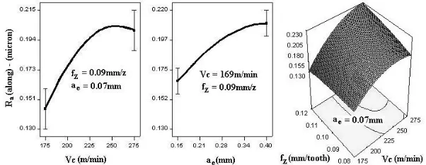
Figure 2 shows the effects of the significant parameters:
Vc, ae, and interaction between Vcand fzupon Ra(along)for the recommended quadratic model. It can be seen that the lower values of Ra(along) can be achieved by setting the lower values of all the three cutting parameters. From the detailed analysis of surface roughness data, it was also concluded that effect of flank wear (for VBmax <0.2mm) upon instantaneous values of arithmetic average roughness of workpiece’s surface was not significant.
C. Averaged Arithmetic Average Surface Roughness, across Feed Direction
Response values for Ra(across) ranged from 0.18 to 0.548μm, providing theratio of maximum to minimum equal to 3.044, and thus, no transformation was required. Linear model was suggested whose ANOVA detail has been provided in table V. Following is the hierarchy of influential cutting parameters: ae; fz; and Vc(marginally significant). The linear empirical model is as follows:
Ra(across) = –0.27944 + 0.000756Vc + 2.243fz + 0.851ae
(3)
The R2for the model is 94.7%, R2-adjusted is 93.4%, and R2-predicted is 90.5%.
Figure 3 shows the effects of the three cutting parameters upon Ra(across) for the recommended linear model. The effect of aeis the most significant one, while the effects of other two parameters are almost equally significant. Lower values of all three parameters lead to the attainment of lower values of Ra(across).
Numerical optimization was utilized to simultaneously minimize Ra(along) andRa(across).Following solution was recommended: Vc = 169m/min; fz = 0.09mm/tooth; ae = 0.07mm. This combination is expected to give Ra(along) values in range of 0.125–0.14μm and Ra(across)values in
range of 0.115–0.13μm. MRR for the said combination is
only 677.8mm3/min (for a
p= 4mm), which is even smaller than the smallest MRR value provided by the combinations used in 16 experiments.
IV. EFFECT OF USING MQL
Experiments No. 2 and 9 (same as 10) were repeated under dry conditions. For the same tool failure criterion, the experiment number 2, under dry condition, experienced tool life of only 1296mm2, as compared to 2546mm2 of life experienced by the same experiment carried under MQL environment. In this case the tool life was reduced to almost half when the cooling environment was changed from MQL to dry. Moving from experiment number 2 to 9 (or 10) means increase in cutting speed and feed rate but decrease in radial depth of cut. The experiment number 9 (or 10), under dry condition, experienced tool life of 942mm2as compared to 977mm2and 1056mm2of tool life values experienced by experiments number 9 and 10, respectively, under MQL environment. In this case the tool life was reduced by 8%, on average. These observations prove that application of MQL to hard-milling process, using carbide cutters, is more beneficial as compared to milling in dry conditions.
V. TOOL WEAR MECHANISMS
Fig. 3. Effects of significant parameters and interaction, upon Ra(across)
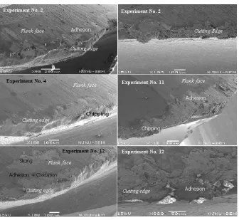
Fig. 4. SEM images of the used tools
The picture related to the experiment 4, shows the cutting edge, which has been damaged by the chipping process. Chipping in this picture appears to be more severe as compared to pictures related to the experiment 2. EDS analysis carried at flank face (near the edge) showed signs of weak adhesion, as high percentages of W, and small percentages of Fe, were detected.
Moving from experiment 2 to 4 means increase in feed rate from value of 0.08 to 0.12mm/tooth, while keeping all other parameters unchanged. This implies that increase in feed rate in hard milling process changes the dominant mode of tool damage from adhesion to chipping. The reason behind this phenomenon is that the cutting edge takes more chip load at higher feed rates and is, thus, likely to be chipped.
The fourth picture in the figure 4 shows the cutting edge and flank face of the tool used in experiment 11. This experiment was run with the smallest value of cutting speed, i.e. 140.9m/min. The picture shows small scale chipping as
well as adhesion. The last two pictures belong to the tool used in experiment 12, the experiment that was run at highest value of cutting speed out of all experiments. The pictures show small scale chipping and very thick adhesion, especially in the last picture. The adhesion was so thick that
Wwas rarely detected in EDS. Besides this, oxidation wear was also detected at the flank face. Extremely high temperature because of ultra-high cutting speed was responsible for oxidation and massive adhesion. Slicing away of small flake of tool’s flank face, because of weakening by adhesion/oxidation, is also clear in the picture. These observations imply that increasing the cutting speed, in hard milling process, increases the intensity of adhesion wear and besides, it also initiates the oxidation wear.
[image:5.612.139.475.194.503.2]VI. CONCLUSIONS
1. Cutting speed is the most influential parameter upon tool life, followed by the feed rate. Tool life can be maximized if the HSM is done at low values of cutting speed and feed rate.
2. Cutting speed and radial depth of cut are highly influential upon roughness of workpiece’s end surface, while the feed rate is slightly influential. In order to minimize the workpiece surface roughness the HSM should be carried at low values of all the three cutting parameters.
3. Application of MQL improves hard milling process by enhancing the tool life.
4. Increase in feed rate accelerates tool chipping process, while increase in cutting speed intensifies the adhesion wear, and it also initiates the oxidation wear.
REFERENCES
[1] K. Nakayama and M. Ogawa, “Burr Formation in Metal Cutting”, Annals of CIRP,vol. 36, no. 1, pp.33-36, 1987
[2] H. Schulz and T. Moriwaki, “High-Speed Machining”, Annals of CIRP, vol. 44, no. 1, pp.637-643, 1992
[3] D.A Axinte and R.C. Dewes, "Tool Wear and Workpiece Surface Integrity when High-Speed Ball Nose End Milling Hardened AISI H13", in: Proc. 3rd Int.Conf. Metal Cutting and HSM, Metz, France, pp. 171-179, 2001
[4] H. Schulz, "Why High-Speed Cutting", in: Proc. Int. Conf. High Speed Machining, Nanjing, China, pp. 1-20, 2001
[5] J. Boehner, M. Dumitrescu, M.A. Elbastawi, T.I. El-Wardany, and L. Chen, "Effect of Carbide Tool Grades and Cutting Edge Geometry on Tool Life during High Speed Machining of Hardened Tool Steel", in: Proc.2nd Int. French German Conf. High-Speed Machining, Darmstadt, Germany, pp. 37-46, 1999
[6] P. Koshy, R.C. Dewes, and D.K. Aspinwall, "High Speed End Milling of Hardened AISI D2 Tool Steel (58HRc)" Journal of Material Processing Technology, vol. 127, pp. 266-273, 2002 [7] J.P. Urbanski, P. Koshy, R.C. Dewes, and D.K. Aspinwall, "High
Speed Machining of Moulds and Dies for Net Shape Manufacture" Materials and Design, vol. 21, pp. 395-402, 2000
[8] Y. Yamada, T. Aoki, S. Kitaura, Y. Tanaka, Y. Okazaki, and H. Hayasaki, "High Speed Cutting Performance of (Al, Ti)N Coated Carbide End Mills for Hardened Steels", in: Proc. first Int. French German Conf. High-Speed Machining, Metz, France, pp. 486-489, 1997
[9] H. Coldwell, R. Woods, M. Paul, P. Koshy, R.C. Dewes, and D.K. Aspinwall, "Rapid Machining of Hardened AISI H13 and D2 Moulds, Dies and Press Tools", Journal of Material Processing Technology, vol. 135, pp. 301-311, 2003
[10] S-P. Lo, "An Adaptive-Network Based Fuzzy Inference System for Prediction of Workpiece Surface Roughness in End Milling",Journal of Material Processing Technology, Vol. 142, pp. 665-675, 2003 [11] D.A Axinte and R.C. Dewes, "Surface Integrity of Hot Work Tool
Steel after High-Speed Milling Data and Empirical Models",Journal of Material Processing Technology, vol. 127, pp. 325-335, 2002 [12] R. Quaile, “Understanding MQL", in website:
http://www.mmsonline.com/articles/010505.html
[13] D.U. Braga, A.E. Diniz, and G.W.A. Miranda, "Using a minimum quantity lubrication and a diamond coated tool in drilling of Al-Si alloys",Journal of Material Processing Technology, vol. 122, pp. 127-138, 2002
[14] M.J. Anderson and P.J. Whitcomb, RSM simplified: Optimizing processes using Response Surface Methods for Design of Experiments,Toronto: Productive Publications Inc., 2004; ISBN 1-56327-297-0
[15] Design-Expert 7; The Source: http://www.statease.com /dx7trial.html [16] G. Derringer, R. Suich, “Simultaneous optimization of several