Abstract—This paper relates to a method for detecting moving objects and track them while the PTZ camera is moving. To ensure that the acquired images are free from blur effect, we have proposed a method to estimate the blur level of the image. For the moving object detection part, we have combined the Wroskian’s change detection method to detect the moving pixels and refine the result by utilizing the neighbor pixels concept to reduce the noise resulted from imperfect alignment of successive images. The detection noise is further reduced by analyzing the detection consistency across successive image frames. This approach has effectively detects the moving object while reducing the noise.
Index Terms— moving object detection, background subtraction, change detection, object tracking, moving camera
I. INTRODUCTION
here are vast models for PTZ cameras in the market nowadays and more PTZ are being installed each year. It is because of its capability to provide larger field of view as compared to static camera. The pan, tilt and zoom capability of PTZ also enable the operator to follow any object of interest in the scene. Besides that, commercial PTZ system can automatically pan, tilt and zoom to the object appear within a preset scene before the preset timer lapsed. The detection is based on motion detection, whereby the biggest motion in the scene will be followed. This would mean that if there are more motion areas/ objects in the scene, only the biggest one will be tracked.
There were works done to integrate PTZ with static camera in a master-slave configuration [1-6]. In this kind of configuration, camera calibration is required to capture the geometric relationship between all cameras. Static camera acts as the master where object detection and tracking are performed. The location of the object in static camera is then transformed and communicated to PTZ networks so that PTZ cameras can follow the detected object. These works are different from us whereby the detection and tracking are done using PTZ instead of using static camera.
Works in [7-8] integrate tracking using single PTZ and background modeling and subtraction to detect object.
Manuscript received Jan 11, 2013; revised Jan 24, 2013. This work was supported in part by the Malaysia’s Ministry of Science, Technology and Innovation. All authors are with MIMOS Berhad, Technology Park Malaysia, 57000 Bukit Jalil, Kuala Lumpur, Malaysia (phone: +603-8995-5000; fax: +603-8991-4221; e-mail: {zulaikha.kadim, marizuana.daud, solehah.radzi, norshuhada.samudin, hockwoon.hon}@mimos.my).
In [7], a mosaic background model is maintained and feature correspondences are performed to find object. In these methods, the success of the detection is achieved at the expense of complex background model initialization and updating.
There are also works related to tracking using single PTZ without background modeling [9-11], where object of interest is mostly human face. Tracking methods such as optical-based [9], kernel-based like mean-shift tracker [10] and particle filter-based schemes [11] are employed.
The contribution of this paper is on the proposed framework that enables the PTZ to do the automatic moving object detection and tracking. In this paper, the system which consists of several main processing components including object detection and tracking is proposed to achieve the above-mentioned objective. In our work, there is no background modeling involved. The detection is done using background subtraction on a number of successive previous frames. To ensure that the successive frames are free from blurring, blur level is estimated by estimating the average edge magnitude in image. To increase the robustness of moving object detection, we have proposed an approach based on the combination of Wroskian’s change detection method and neighbor pixel concept. The detection result is further refined by analyzing the detection consistency to remove noise.
This paper is organized as follows. Section II describes in detail the architecture and algorithms for the proposed system. Then, the following section presents the experimental setup and results. The conclusion will be drawn at the end to conclude the paper.
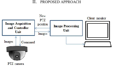
[image:1.595.313.550.588.726.2]II. PROPOSED APPROACH
Fig. 1. Architecture of proposed PTZ system
As illustrated in Fig. 1, the proposed PTZ system consists of PTZ camera and controller unit to capture and control the positioning of PTZ; image processing unit and client
Method to Detect and Track Moving Object in
Non-static PTZ Camera
Zulaikha Kadim, Marizuana Md. Daud, Syaimaa Solehah M. Radzi, Norshuhada Samudin, Hon
Hock Woon
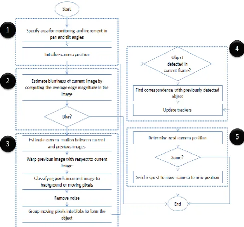
monitor to process and display images captured by the camera respectively. There are 5 major processing components which reside within the image processing unit, which includes include video analytics initializer, camera stability checker, object detector, object tracker and next position determination component. Processes involved in each component are shown in Fig. 2.
Fig. 2.Main process flow for the proposed system. Numbers in black circle indicates the respective component.
A. Video Analytics Initializer
In this component, video analytics parameters such as the area for monitoring, the pan and tilt angle increments and minimum and maximum range for a human are specified. Area of monitoring is specified by giving the starting and ending angles for the PTZ to navigate. If the PTZ is set to monitor 360º, then the starting and ending pan angles are the same. The increment pan and tilt angles are required to compute the next PTZ position. These increment angles are denoted as Δp and Δt for pan and tilt respectively. Basically these are the required angles to obtain two successive images that are 50% overlap to each other in horizontal and vertical direction. Then, at start, the system will send request to move PTZ to the pre-set’s starting angles.
B. Camera Stability Checker
This component is responsible to ensure that acquired images are free from motion blur. It means that the image must be acquires while the camera is at stable position. Images acquired while PTZ is steering to the intended position will suffer the blurring effects. These blurred images will affect the accuracy of feature point detector and matching, subsequently decreasing the accuracy of object detector component.
As part of this work, we have proposed a method to determine whether an image frame is blurred or not, derived from the work presented in [16]. In [16], Marziliano et.al. have proposed a method for estimating perceptual blur by measuring the average width of the vertical edges in the image. Perceptual blur is defined in spatial domain as the
spread of the edge. To do this, first a vertical edge detector is applied to the image. Then each row of the edge image is scanned to find the edge location. For pixel corresponding to edge location, the start and end of the edge is estimated by finding the local extrema that closest to the pixel. The difference between the start and end will give the edge width. The drawback of this approach is the high amount of work to be done to check every row of the image and finding the local extrema for each edge pixel point. It is reported in their work that the performance is near real-time.
In our work, we will also estimate blur based on the strength of the edge and how much the spread of the edge in the image. First, edge detector is applied on the image (e.g. Sobel). For a sharper edge, the intensity change at the edge point is more abrupt as compared to a blurred edge. This will results in a higher edge magnitude in sharper edge. Sharper edge is also spread into a lesser number of pixels. For that reason, we compute the average absolute edge magnitude of the edge pixels in the image to estimate the blurriness level. The lower the average value shows that the image is more blur. By computing the average edge magnitude instead of finding the local extrema for each edge pixels, the performance of the method is improved.
Fig. 3(c) illustrates an example of intensity profiles of a sharp and blurred edge point computed from the edge image in Fig. 3(b). It is shown that the edge magnitude of a sharp edge is higher and it is spread across a lesser number of pixels. Thus it provides a higher average edge magnitude than the blurred edge.
(a) (b)
(c)
[image:2.595.305.550.429.716.2]C. Object Detector
The objective of this component is to detect moving object in the image after the camera is stable. As illustrated in Fig. 3, the process consists of five steps; estimating camera motion between successive images, warping previous image with respect to current image, classifying the pixels in current image into background or moving pixels, removing noise and finally group the moving pixels into blob to form the object.
To estimate the camera motion, homography between previous and current image is computed. The computed homography will be used to compensate previous image with respect to current image, to finally classify the pixels into background or moving pixels. The process starts with extracting feature points in current and previous images. Then all feature points not correspond to previously moving object will be selected and maintained in previous images. The rest of the feature points will be removed. This step is done to ensure that feature points belong to previously detected moving object is not considered for estimating the camera motion model between previous and current images. Then, at each of selected feature points, the descriptors are computed. In this work, Harris keypoint detector and SURF (Speeded Up Robust Feature) descriptor [12] algorithms are
utilized due to their good performances in various scenarios [17]. After that, point correspondences between all selected feature points in current and previous images are established. These correspondences are then used to estimate the homography that defines the transformation from previous to current image. Before the homography is used to compensate the previous images, it needs to be validated. If the homography is not valid, the detection process in current image will be terminated and the process continued with the next image frame.
There are two criteria used to validate the homography. A homography matrix, H is a 3-by-3 matrix. Initially the homography matrix is decomposed using SVD (singular value decomposition) into three 3-by-3 matrices; orthogonal matrix U, pseudo-diagonal matrix , and orthogonal matrix V. The first criterion is to check the range for diagonal elements of . Since the diagonals of contain the singular values of H, then theymust be real and positive. The second criterion is the ratio of these diagonals, which must be within certain range. The ratio is computed as in (1). In this work the valid ratio value is set to be less than 500. If a homography matrix satisfies both criteria, then it is deemed as valid.
(1)
If the homography is valid, then the next step is to classify each pixel in current image whether it is a moving or background pixel. For this step, we are utilizing area-based background subtraction approach [18] and refine the result using a neighbor pixel concept [19].
In area-based background subtraction approach, initially the previous image is warped with respect to current image
using the computed homography. Then background subtraction is performed between current and warped previous image. To increase the robustness of the background subtraction, we have implemented the Wroskian change detector as presented in [18] due to its invariance to illumination, capability to remove shadow and reflection and less dependent on threshold. Wroskian detector is applied on Y-component of the image (YUV color model).
To determine whether a pixel has changed in current image with respect to warped previous image, the Wroskian model, W and its inverse ratio, W* are computed within a small window of n number of pixels. The Wroskian model and its inverse ratio are the ratios of pixel intensity in both images (x and y denote the pixel intensity in current and warped previous image respectively) as defined in Eq. 2 and Eq. 3. W and W* are used to detect high and low value ratios respectively.
(2)
(3)
For the detection of pixel change, both calculations, W and W* must be positive. In this work, we used thresholds of 5 and 0.6 for W and W* respectively. Pixel identified as change (W and W* values are more than the thresholds) is classified as moving pixel. The union of both calculations will result in the final motion map. Motion map is the binary image which indicates moving (non-zero pixel) and background pixels.
Next the motion map is refined using neighbor pixel concept. This step is introduced to reduce the detection noise due to imperfect alignment between previous and current image. The diagonal ratio computed earlier is used to determine whether refinement is needed or not. If the ratio is more than a level, then only refinement will come in.
To refine the motion map, all pixels identified as moving pixel will be evaluated. Let say, Xc is a moving pixel in current image, and Xb is the corresponding pixel in warped previous image. Then to re-classify Xc, the neighbor pixels of Xb within a small window will be examined and the intensity difference between the neighbor pixel and current pixel is computed and the minimum difference is recorded. If the minimum difference is small, then current pixel, Xc is re-classified as a background pixel. Connected component labeling is then applied on the resultant motion map, to group connected moving pixels into moving blob.
TABLE 1
ALGORITHM FOR REMOVING NOISE BY ANALYZING THE DETECTION CONSISTENCY
Given the detected moving blobs in current image, determine whether each detected blob is a valid moving blob or noise.
For each detected moving blob in current image,
For each feature points within the box enclosing the blob Find matched feature points in previous image Count number of matched feature points that reside within a box enclosing detected moving blob in previous image
End For
If counter is more than a threshold, Detected moving blob is valid Else
Detected moving blob is noise End
End For
D. Object Tracker
After detection, process will continue with the object tracker component. In this work, object tracking will find the correspondences between object detected in successive frames. The camera position will be changed based on new tracked location to ensure that the object is still visible within camera view for a number of frames, M (in this paper, M is set to five frames). After that, the camera will stop tracking the object and start finding other moving objects. At the end of this tracking step, each detected objects in current frame will be labeled using a non-zero number indicating its tracking identity across a successive number of frames.
Referring to Fig. 4, if there is object detected in current frame, then the correspondences between objects in current and previous frames will be established. To find correspondence, k number of nearest objects in previous frames with respect to detected object’s centroid will be examined. Then current object will be assigned the same label as the previous object which it is most similar with. Illustration for this step is shown in Fig. 5. The maximum radius for searching area is set to be not more than 25% of image width. If there is no nearest object within the maximum radius from a detected object, then the detected object is assumed to be a new object. In this case, a new tracker will be initialized to keep the tracking information (e.g. color, motion properties and object label) of this new object. This new object will be assigned a new unique object label.
If there is no object detected in current frame, it is assumed that the object has left the scene, thus the tracker lists need to be updated by removing all previously tracked objects in the list.
In this paper, we are using Hue-Saturation-Value (HSV) histogram as in [13] to represent color properties of each object. In this scheme, the resulting histogram is composed of N bins, whereby N=NhNs+Nv. Nh, Ns and Nv are the number of bins in hue, saturation and value channels respectively. The idea of [13] is to decouple chromatic information from shading effects. It is found that color information is only reliable if the saturation and value is not too small, thus only pixels with saturation and value more than 0.1 and 0.2 (respectively) will be processed. In this
paper, we set Nh, Ns and Nvto 10, thus will results in N=110 as in [14].
Then to compute similarity between two HSV histograms, the bhattacryya distance [15] will be used as in Eq. (4).
) (4)
Where d(p,q) is the distance between normalized feature vectors p and q of length m. The lower the distance, then more similar the two vectors are.
Fig. 4. Searching area for finding correspondences between detected objects in current and previous image; k is set to 2. The blue and red dotted circles are corresponding to the searching area for blue and red objects in current frames. Searching area for blue object covering 2 nearest objects in previous image, while for red object the searching area is set to be maximum. Similarity checking will be done between current object and all previous objects within its searching area. The most right image shows that the blue object in current image is assigned label 2; same as its correspondence in previous image. Red object is assigned a new label (label 3) since no correspondence exist within its searching area.
E. Next Position Determination
The aim of this component is to determine where the PTZ should be moved next. To perform this task, first the PTZ current movement state is determined, and then only the next PTZ position is computed.
[image:4.595.305.565.203.278.2]We have defined a number of movement states as listed in Table 2. There are three parameters used to deduce the state status of the system, which are the stable status from camera stability checker component, object detection and tracking information from object detector and tracker components. The next position of the PTZ will then be determined based on the current status of the system (please refer to Table 2).
(denoted as pr and tr for pan and tilt angles respectively) .After the object has been tracked for M frames, the state is changed to REINSTATE; whereby the tracking of current object is stopped and the PTZ will move back to the predefined touring path. In this case the next PTZ location is set to the previously restored angles.
TABLE 2
POSSIBLE MOVEMENT STATES FOR PTZ, CONDITIONS TO BE IN AND COMPUTATION OF NEXT POSITION FOR EACH OF THE
STATE. PT+1 AND TT+1ARE THE NEXT PAN AND TILT ANGLE
RESPECTIVELY, WHILE PT AND TT CORRESPOND TO CURRENT
ANGLES. ΔP ANDΔT ARE THE INCREMENT IN PAN AND TILT
ANGLE SET IN VIDEO ANALYTICS INITIALIZER COMPONENT. State name Conditions to be in the
state
Next position (pan, tilt angles) NO_CHANGE PTZ is not at stable
position OR object tracked is still within current view
pt+1 := pt tt+1 := tt
PAN No object detected after a
number of frames AND not reach starting or ending pan angle
pt+1 := pt ± Δp tt+1 := tt
TILT No object detected after a number of frames AND reach starting or ending pan angle
pt+1 := pt tt+1 := tt ± Δt
FOLLOW_OBJECT Object tracked for less than M frames and at the edge of current view
pr := pt tr:= tt pt+1 := pt ± Δpt+1
tt+1 := tt ± Δtt+1
Please refer to Fig. 7 for detailed illustration. REINSTATE Object has been tracked
for M frames
pt+1 := pr tt+1 := tr
For FOLLOW_OBJECT state, the steps involved to determine next PTZ position are illustrated in Fig. 5. First, the center point of all tracked object will be determined by taking the average objects coordinates as in Eq. (5). If there is only one object to be tracked, the center point is set as the object’s centroid. This center point will be the targeted new image center after the camera is moved. To find the required angle for the camera to move, horizontal and vertical distance between the computed center point and image center is calculated as in Eq. (6). Then the required angles are computed as in Eq. (7).
and (5)
where xo and yo are the x and y coordinate for centre point of all N objects coordinates (xi, yi).
Let, (xo, yo) and (xc, yc) are the center point of all objects
in the image and the image centroid, thus horizontal distance, dx and vertical distance, dy between the two points
are as follows:
and (6)
and (7)
where Δpt+1 and Δtt+1 are the angles required to move the
camera to the next position, w and h are the width and height of the image, and Δp and Δt are the incremental angles set in video analytics initializer component; camera movement angles to obtain adjacent images which differ by 50% of the image width and height respectively.
Fig. 5. Process flow for determining next PTZ position for FOLLOW_OBJECT state.
III. EXPERIMENTAL RESULTS
In this section, results for proposed image processing components are presented, which include the camera stability checker and moving object detector.
[image:5.595.305.565.425.525.2]A. Camera stability checker component
Fig. 6. Average edge magnitude vs. image frames. Arrows highlight the image frames while camera is at stable position. While the PTZ is streering to the next position, the average edge magnitude is dropped indicating that the images are blurred due to camera is in motion.
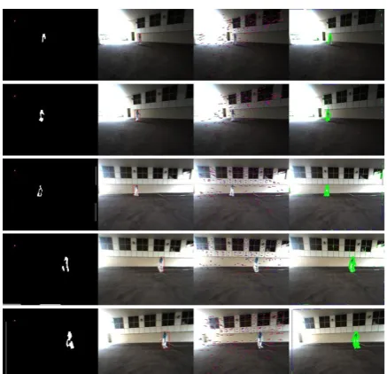
[image:5.595.340.513.590.662.2]B. Object detector component
Fig. 8. Sample results for object detection across multiple frames. First column shows the motion map. The colored dot on the motion map image is indicates that current image is not blurred. Second column shows the final moving object detection. Third column shows the feature point tracking between current and previous frames. Forth column shows the motion map overlayed on current image. This motion map is generated using pixel-wise background subtraction (RGB color model) between current and warped previous image. Comparing to the motion map obtained using Wroskian’s method (first column), noise are more apparent when pixel-wise background subtraction is used.
Fig. 9. Sample results for homography validity test for invalid cases. The diagonal values for both cases are high.
Fig. 10. Sample results for homography test for valid cases. The diagonal values for both cases are low.
Fig. 11. Sample result for removing noise by analyzing the detection
in red boxes. In frame #993, from the motion map generated, there are noise blobs detected as moving blobs at the edge of the windows, however, the blobs are deemed as noise as they are not detected as moving blobs in previous frame. Thus the final detection shows only two moving objects detected in that image. In frame #994, the noise blobs disappeared. Most of the time, noise blobs are not consistently appear over successive frames, thus, by analyzing the detection consistency, we may remove them effectively.
REFERENCES
[1] N. Bellotto, E. Sommerlade, B. Benfold, C. Bibby, I. Reid, D. Roth, C. Fern´andez, L. V. Gool, and J. Gonz`alez. 2009. A distributed camera system for multi-resolution surveillance. In Proc. of the 3rd ACM/IEEE Int. Conf. on Distributed Smart Cameras (ICDSC), (2009).
[2] C. Chen, Y. Yao, C. Jr., B. Abidi, A. Koschan, and M. Abidi. 2008. Heterogeneous fusion of omnidirectional and ptz cameras for multiple object tracking. IEEE Trans. Circuits Syst. Video Techn, 18, 8, (2008), 1052–1063.
[3] X. Cindy, F. Collange, F. Jurie, and P. Martinet. 2001. Object tracking with a pan-tilt-zoom camera: application to car driving assistance. IEEE Int. Conf. on Robotics and Automation (ICRA), 2, (2001), 1653–1658.
[4] Kang, B. Abidi, and M. Abidi. 2004. Integration of color and shape for detecting and tracking security breaches in airports. Int. Carnahan Conf. on Security Technology, (2004), 289–294. [5] N. Krahnstoever, T. Yu, and S. Lim. 2008. Collaborative real-time
control of active cameras in large scale surveillance systems. European Conf. on Computer Vision (ECCV).
[6] S.-N. Lim, A. Elgammal, and L. Davis. 2003. Image-based pan-tilt camera control in a multi-camera surveillance environment. In Proceedings on Int. Conf. on Multimedia and Expo (ICME), 1, (2003), 645–648.
[7] S. Kang, J. Paik, A. Koschan, B. Abidi, and M. Abidi. 2003. Real-time video tracking using ptz cameras. 6th Int. Conf. on Quality Control by Artificial Vision, (2003), 103–111.
[8] Y. Yao, B. Abidi, and M. Abidi. 2006. 3D target scale estimation and motion segmentation for size preserving tracking in ptz video. In Proceedings of the IEEE Conference on Computer Vision and Pattern Recognition Workshop (CVPRW), (2006), 130–136. [9] M. Roha, T. Kima, J. Park, and S. Lee. 2007. Accurate object contour
tracking based on boundary edge selection. Pattern Recognition, 40, 3, (2007), 931–943.
[10] W. Qu and D. Schonfeld. 2008. Robust control-based object tracking. IEEE Transactions on Image Processing, 17, (2008), 1721–1726. [11] Y. Li, H. Ai, T. Yamashita, S. Lao, and M. Kawade. 2008. Tracking
in low frame rate video: a cascade particle filter with discriminative observers of different life spans. IEEE T-PAMI, 30, 10, (2008), 1728–1740.
[12] H. Bay, A. Ess, T. Tuytelaars, L.V. Gool. 2008. Surf: Speeded up robust features. CVIU (2008).
[13] P. Pe´rez, C. Hue, J. Vermaak, M. Gangnet. 2002. Color-based probabilistic tracking. European Conference on Computer Vision, (2002), 661–675.
[14] Z. Li, K. Yabuta, H. Kitazawa. 2009. A new method for moving object extraction and tracking based on the exclusive block matching. Springer-Verlag Berlin Heidelberg, PSIVT 2009, LNCS 5414, (2009), 249–260.
[15] Bhattacharyya, A. 1943. On a measure of divergence between two statistical populations defined by their probability distributions. Bulletin of the Calcutta Mathematical Society, 35, (1943), 99–109. [16] Marziliano, P.; Dufaux, F.; Winkler, S.; Ebrahimi, T. “A no-reference
perceptual blur metric,” Int. Conf. on Image Processing, 3, pp. 57-60, 2002.
[17] Mikolajczyk, K.; Schmid, C.; , "A performance evaluation of local descriptors," Pattern Analysis and Machine Intelligence, IEEE Transactions on , vol.27, no.10, pp.1615-1630, Oct. 2005.
[18] Durucan, E.; Ebrahimi, T.; “Change detection and background extraction by linear algebra,” Proceedings of the IEEE , vol.89, no.10, pp.1368-1381, Oct 2001
[image:6.595.64.283.73.284.2] [image:6.595.83.267.514.605.2] [image:6.595.107.240.638.767.2]