SYNTHESIS, CHARACTERISATION AND ADSORPTION PROPERTIES OF METAL-ORGANIC FRAMEWORKS AND THE
STRUCTURAL RESPONSE TO FUNCTIONALISATION AND TEMPERATURE
John Patrick Stephen Mowat
A Thesis Submitted for the Degree of PhD at the
University of St. Andrews
2012
Full metadata for this item is available in Research@StAndrews:FullText
at:
http://research-repository.st-andrews.ac.uk/
Please use this identifier to cite or link to this item: http://hdl.handle.net/10023/3195
This item is protected by original copyright
Synthesis, Characterisation and Adsorption
Properties of Metal-Organic Frameworks
and the Structural Response to
Functionalisation and Temperature.
A thesis presented for the degree of
Doctor of Philosophy
In the Faculty of Science of the University of St. Andrews
1. Candidate’s declarations:
I, John Mowat, hereby certify that this thesis, which is approximately 49,500 words in length, has been written by me, that it is the record of work carried out by me and that it has not been submitted in any previous application for a higher degree.
I was admitted as a research student in October, 2008 and as a candidate for the degree of Doctor of Philosophy in October, 2009; the higher study for which this is a record was carried out in the University of St Andrews between 2008 and 2012.
Date ……… signature of candidate ………
2. Supervisor’s declaration:
I hereby certify that the candidate has fulfilled the conditions of the Resolution and Regulations appropriate for the degree of Doctor of Philosophy in the University of St Andrews and that the candidate is qualified to submit this thesis in application for that degree.
Date ……… signature of supervisor ………
3. Permission for electronic publication: (to be signed by both candidate and supervisor)
In submitting this thesis to the University of St Andrews I understand that I am giving permission for it to be made available for use in accordance with the regulations of the University Library for the time being in force, subject to any copyright vested in the work not being affected thereby. I also understand that the title and the abstract will be published, and that a copy of the work may be made and supplied to any bona fide library or research worker, that my thesis will be
electronically accessible for personal or research use unless exempt by award of an embargo as requested below, and that the library has the right to migrate my thesis into new electronic forms as required to ensure continued access to the thesis. I have obtained any third-party copyright permissions that may be required in order to allow such access and migration, or have requested the appropriate embargo below.
Date ……… signature of candidate ……… signature of supervisor ………
The following is an agreed request by candidate and supervisor regarding the electronic publication of this thesis:
Abstract
The synthesis of a scandium aluminium methylphosphonate ScAl3(CH3PO3)6 isostructural to the
aluminium methylphosphonate AlMePO-α and with permanent microporosity is reported here
for the first time. Structural characterisation of three lanthanide bisphosphonate structures
(I,II,III) with the light lanthanides and N,N’-piperazine bis-(methylenephosphonic acid) and its
2-methyl and 2,5-dimethyl derivatives is described. The framework of structure type I shows
considerable flexibility upon dehydration with a symmetry change from C2/c, a = 23.5864(2) Å,
b = 12.1186(2) Å, c = 5.6613(2) Å, β = 93.040(2)˚) in the hydrated state to P21/n, a = 21.8361(12) Å, b = 9.3519(4) Å, c = 5.5629(3) Å, β = 96.560(4)˚ after dehydration. This cell volume reduces by 27% on dehydration and is accompanied by a change in the conformation
of the piperazine ring from chair to boat configuration. The structures of type I (hydrated and
dehydrated) were refined against synchrotron powder X-ray diffraction data. Despite the
reversible hydration and flexibility, the structures possess no permanent porosity.
Investigation of the solvothermal chemistry of scandium carboxylates identified routes to 7
framework structures 5 of which were previously unreported in the scandium system. Lower
temperature solvothermal reactions using terephthalic acid (80 - 140°C using
dimethylformamide and diethylformamide) yielded two scandium terephthalates, MIL-88B(Sc)
and MIL-101(Sc), identified by laboratory X-ray powder diffraction. Whereas higher
temperature (160 – 220°C), reactions gave MIL-53(Sc) and Sc2BDC3. Further study with the tri-
and tetra-carboxylate linkers, trimesic acid, 3,3’,5,5’-azobenzenetetracarboxylic acid and
pyromellitic acid yielded MIL-100(Sc), Sc-ABTC and Sc4PMA3 respectively. Structural
identification of MIL-100(Sc) and Sc-ABTC was performed by means of X-ray powder diffraction
analysis and of Sc4PMA3 by single crystal X-ray diffraction.
The structure of a small pore scandium terephthalate Sc2BDC3 was investigated as a function of
temperature and of functionalization. In situ synchrotron X-ray diffraction data, collected on a Sc2BDC3in vacuo, enabled a phase change from orthorhombic Fddd to monoclinic C2/c and the associated structural effects to be observed in detail. The orthorhombic structure displayed a
The structure of Sc2BDC3 and the functionalised derivatives were solved using Rietveld analysis
on synchrotron X-ray powder diffraction data. Sc2(NH2-BDC)3 was solved using the
orthorhombic Sc2BDC3 framework starting model and, over the temperature range studied,
stayed orthorhombic Fddd. Sc2(NO2-BDC)3, was shown to be monoclinic C2/c over the same temperature range, a result of the steric effects of the bulky –NO2 group in a small pore
framework. Partial ordering of the functional groups was observed in both Sc2(NH2-BDC)3 and
Sc2(NO2-BDC)3. The strength of interaction for the Sc2(NH2-BDC)3 with CO2 was higher than that
of the parent Sc2BDC3 due to the strong –NH2···CO2 interaction. Despite the inclusion of a
relatively large –NO2 group along the walls of a channel ~4 Å in diameter the Sc2(NO2-BDC)3 still
showed permanent microporosity to CO2 (2.6 mmol g-1) suggesting that there must be some
motion in the -NO2 group to allow the CO2 molecules to diffuse through the channels.
The scandium analogue of the flexible terephthalate MIL-53, a competitive phase in the
synthesis of Sc2BDC3, was prepared and characterised by Rietveld analysis on synchrotron
X-ray powder diffraction data using a combination of literature structural models and models
obtained from single crystal X-ray diffraction experiments. Experimental solid state 45Sc, 13C
and 1H NMR data combined with NMR calculations on the structural models produced from
diffraction analysis were used to identify the hydrated (MIL-53(Sc)-H2O), calcined
(MIL-53(Sc)-CAL) and high temperature (MIL-53(Sc)-HT) structures of MIL-53(Sc). Further to this the
2-nitroterephthalate derivative, MIL-53(Sc)-NO2, was prepared and characterised using single
crystal X-ray diffraction. The adsorptive properties of the parent terephthalate and the
functionalised derivative were compared and in both cases showed a breathing behaviour,
exemplified by steps in the adsorption isotherms. MIL-53(Sc)-CAL was found to possess a
closed pore configuration in the dehydrated state, a previously unreported structural form for
the MIL-53 series, and its presence can be observed in the low pressure region of the CO2
adsorption isotherm as a non-porous plateau.
The selectivity and separation properties of two MOFs, the nickel bisphosphonate, STA-12(Ni)
and the scandium carboxylate, Sc2BDC3 were measured using breakthrough curves on mixtures
of CH4 and CO2. The results showed both materials to be highly selective in the adsorption of
CO2 over CH4. Column testing using a PLOT column of STA-12(Ni) and a packed column of
Sc2BDC3 showed promising preliminary results with STA-12(Ni) displaying effective, baseline
separation on low boiling point hydrocarbon mixtures (C1 – C4) while the smaller pore channels
of Sc2BDC3 were effective in the size selective separation of higher boiling point branched and
Acknowledgments
First and foremost I would like to thank my supervisor, Professor Paul Wright, for his
supervision from my undergraduate studies through to the opportunity to carry out this
research. His knowledge, support and enthusiasm has been exceptional and the major factor in
the success of this work. One could not ask for more from a supervisor.
I would also like to thank all the collaborators with whom I have worked throughout this
project, their expertise and contribution to this work has been invaluable. I thank Dr. Stuart
Miller for his friendship, guidance and mentoring, and for his work that formed a basis for this
study. I am grateful to Dr. Sharon Ashbrook, Dr. John Griffin and Valerie Seymour for their
prompt and thorough collection and analysis of solid-state NMR data. I thank Professor Alex
Slawin and Dr. Stephen Moggach for their help and support with crystallography. For their help
and support in the computer simulation of adsorption, I thank Dr. David Fairen-Jimenez, Dr.
Tina Düren and Ana-Maria Banu. Mrs Sylvia Williamson is thanked for the collection of
adsorption and thermal analysis data and for training on how to use on the instruments.
My thanks also go to all friends and colleagues within the Chemistry department including
Charlotte Jones, Magdalena Lozinska, Juergen Kahr, Lewis Downie, Cameron Black, Laura
Mitchell, members of the Wright group with special thanks to Michael Wharmby for
proof-reading and generally bouncing ideas off. Beyond Chemistry, I would like to thank my best
friend (and best man) David Armstrong and all the friends who made University an enjoyable
and memorable experience with special thanks to William Barber, Barry Barkey and Damien
Phillips.
Most importantly, I thank my wife Catherine for her love, support and encouragement without
which, this thesis would not have been possible.
Finally I thank my parents, Philip and Deirdre Mowat, for their love and support throughout
this project and my education as a whole and my Gran, Dorothy Mowat, for making me the
Dedication
Publications arising from this work
1. Lanthanide N,N'-piperazine-bis(methylenephosphonates) (Ln = La, Ce, Nd) that display flexible frameworks, reversible hydration and cation exchange. John P. S. Mowat, John A . Groves, Michael T. Wharmby, Stuart R. Miller, Yang Li, Philip Lightfoot and Paul A. Wright.Journal of Solid State Chemistry, 182, 2009, 2769-2778.
2. Synthesis and crystal chemistry of the STA-12 family of metal
N,N’-piperazinebis(methylenephosphonate)s and applications of STA-12(Ni) in the separation of gases. Michael T. Wharmby, Gordon M. Pearce, John P.S. Mowat, John M. Griffin, Sharon E. Ashbrook, Paul A. Wright, Lars-Hendrik Schilling, Alexandra Lieb, Norbert Stock, Sachin Chavan, Silvia Bordiga, Edder Garcia, Gerhard Pirngruber, Martin Vreeke, and Leszek Gora., Microporous and Mesoporous Materials, 2011, article in press, DOI:
10.1016/j.micromeso.2011.12.003
3. Synthesis, characterisation and adsorption properties of microporous scandium carboxylates with rigid and flexible frameworks. John P. S. Mowat, Stuart R. Miller, Alexandra M. Z. Slawin,Valerie R. Seymour, Sharon E. Ashbrook and Paul A. Wright., Microporous and Mesoporous Materials, 142, 2011, 322-333.
4. Structural Chemistry, Monoclinic-to-Orthorhombic Phase Transition, and CO2
Adsorption Behaviour of the Small Pore Scandium Terephthalate,
Sc2(O2CC6H4CO2)3, and Its Nitro- And Amino-Functionalized Derivatives. John P.
S. Mowat, Stuart R. Miller, John M. Griffin, Valerie R. Seymour, Sharon E. Ashbrook, Stephen P. Thompson, David Fairen-Jimenez, Ana-Maria Banu, Tina Düren, and Paul A. Wright., Inorganic Chemistry, 50, 2011, 10844-10858. 5. A novel structural form of MIL-53 observed for the scandium analogue and its
response to temperature variation and CO2 adsorption.John P. S. Mowat,
Table of Contents
1 Introduction... 1
1.1 Overview ... 2
1.2 Zeolites and Zeotypes ... 5
1.3 Metal Phosphonates and Bisphosphonate MOFs. ... 7
1.3.1 AlMePOs ... 7
1.3.2 Metal Bisphosphonates... 9
1.4 Carboxylate MOFs... 12
1.4.1 Divalent Carboxylates... 12
1.4.2 High surface area materials... 15
1.4.3 Trivalent Carboxylates... 17
1.4.4 Framework flexibility in MOFs... 27
1.4.5 Scandium Chemistry and MOF synthesis ... 28
1.5 Column Chromatography... 34
1.5.1 MOF-508... 34
1.5.2 MIL-47... 36
1.5.3 MIL-101... 37
1.5.4 Column summary... 39
1.6 Aims ... 40
2 Experimental Methods ... 41
2.1 Synthesis Methods... 42
2.2 Characterisation of Materials ... 43
2.2.1 X-ray Diffraction... 43
2.2.2 Rietveld Refinement and Le-Bail method ... 49
2.2.4 Chemical Analysis (CHNS and EDX) ... 57
2.3 Adsorption ... 58
2.4 Computational Modelling... 61
2.4.1 Structure optimization... 61
2.4.2 Adsorption simulation ... 62
2.5 Columns and Chromatography... 64
2.5.1 ZLC ... 64
2.5.2 Breakthrough Curves... 65
3 Phosphonates ... 67
3.1 Scandium substituted AlMePOs ... 68
3.2 Lanthanide Bisphosphonates... 74
3.2.1 Synthesis conditions ... 75
3.2.2 Structural characterisation... 77
3.2.3 Summary of lanthanide bisphosphonate studies... 88
3.3 Column experiments on the nickel bisphosphate, STA-12... 89
3.3.1 Synthesis... 90
3.3.2 Breakthrough experiments... 91
3.3.3 PLOT column... 95
3.4 Summary of metal phosphonate studies... 98
4 Synthesis of Scandium Carboxylates ... 100
4.1 Overview ... 101
4.2 Experimental... 104
4.4 Scandium trimesates ... 129
4.5 Scandium Tetracarboxylates... 135
4.5.1 Sc-PMA... 135
4.5.2 Sc-ABTC... 139
4.6 Summary of scandium carboxylate syntheses... 149
5 Synthesis, Characterisation and Functionalisation of Sc2BDC3... 150
5.1 Introduction ... 151
5.2 Aims ... 155
5.3 Experimental... 155
5.4 Results... 158
5.4.1 Synchrotron Powder X-ray Diffraction studies... 158
5.4.2 Solid-State NMR... 174
5.4.3 Adsorption Studies ... 178
5.4.4 Adsorption Simulation... 181
5.4.5 Breakthrough curves and Column testing on Sc2BDC3... 186
5.5 Summary... 190
6 MIL-53(Sc)... 196
6.1 Introduction to MIL-53... 197
6.2 Structure Characterisation... 205
6.2.1 Variable temperature studies... 212
6.2.2 Solid state NMR ... 215
6.2.3 Functionalised MIL-53(Sc) ... 217
6.2.4 Adsorption studies... 220
6.3 Summary... 228
7.1 General summary... 231
7.2 Further work ... 235
8 References... 237
Chapter 1 Introduction
1
Chapter 1 Introduction
1.1 Overview
Porous solids have attracted considerable interest in recent years1 primarily for
applications in gas storage,2-5 separation and purification.6-8 In addition, they have
been explored for use in a wide variety of other applications including magnetism9,
drug delivery10 and catalysis.11 The term porous solids encompasses a wide range of
materials including zeolites, zeotypes, porous carbons and, more recently, metal organic frameworks12 (MOFs), zeolitic imidazolate frameworks13 (ZIFs) and covalent
organic frameworks14 (COFs). Zeolites, both naturally occurring and synthetic
derivatives - in some ways the parent class of materials in porous solids - have many current commercial applications covering a broad range of areas from catalysis,15such as cracking of alkanes,16to use as adsorbents in household powder detergents.17 MOFs have attracted particular interest as adsorbents and have a number of potential advantages over zeolites and porous carbons which are the current industry standard.18Traditionally, zeolites have been chosen for their fixed size and adsorption properties7, leading to use as molecular sieves (size selective process) and in gas separation e.g. N2/O219,20(adsorption selective separations).
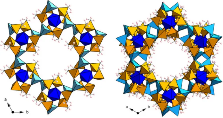
One of the main advantages of MOF materials over the conventional zeolites and porous carbons is in the tunability of the materials both pre-synthesis21 and post-synthesis22,23. In MOF materials, it is possible to add functional groups, vary the framework forming metal cation and alter the pore size while retaining a particular framework topology, exemplified by the honeycomb-like structure of the isoreticular St. Andrews porous materials, STA-12(Ni)24 and STA-16(Co)25 (Figure 1.1). This
Chapter 1 Introduction
3
Figure 1.1: View down the hexagonal channels in the honeycomb like pore structure of metal bisphosphonates STA-12(Ni) (left) and STA-16(Co) (right). Metal octahedra are shown in green and blue for nickel and cobalt respectively. Phosphonate tetrahedra are shown in orange and black spheres represent the carbon atoms of the organic linker.
MOF materials, also referred to as hybrid porous solids12 or coordination polymers,26 consist of inorganic fragments joined with organic linking molecules (ligands). The inorganic fragments can consist of various different metal environments including iso-lated polyhedra,27 clusters,28 chains29 and layers30 which are linked by the organic molecules to form framework materials (Figure 1.2). MOF materials can crystallise over a wide range of particle sizes from microcrystalline powders (< 1 μm3particles) up to
larger single crystals (> (150 μm)3). As MOFs are crystalline, the pore systems are well
defined throughout the material enabling better reproducibility and uniformity of sorption properties when compared with amorphous porous carbons and silicas.
Chapter 1 Introduction
MOFs tend to be categorised by the type of functional group on the organic linker involved in the framework. The most studied classes are carboxylates, amines, and phosphonates. Ligands which contain the same functional groups but with a different organic connectivity, for example linear dicarboxylates (including benzene-1,4-dicarboxylate, biphenyl-4,4’-dicarboxylate etc.) can lead to a series of isoreticular materials which are topologically identical but the organic linking molecule is extended.31This is exemplified by the MOF-5 structure32(also referred to as IRMOF-1) and series of related frameworks IRMOFs 2-1631 where the same Zn4O(CO2)6 clusters
form the inorganic core, whilst the ligand between the carboxylate groups is varied with retention of the cubic network of channels (Figure 1.3).
Figure 1.3: IRMOF series including (from left to right) IRMOF-1,8,10, 12 and 16, where the Zn4O(CO2)6 clusters are pillared by dicarboxylate linkers of increasing
length.31Yellow spheres indicate the location of the cavities in the cubic cage.
Chapter 1 Introduction
5
tend to have significantly lower thermal stability than zeolites but some examples of MOFs with strong metal - ligand bonds and stable organic components have shown thermal stability, in air, greater than 550°C in a porous MOF27 and over 600°C in a
higher density non-porous MOF.36
1.2 Zeolites and Zeotypes
The name zeolite is derived from the greek words ‘zeo’ and ‘lithos’ translating as boiling stones and was the result of the work by the Swedish mineralogist Axel Fredrick Cronstedt.37He observed that a naturally occurring mineral, stilbite, visibly lost water
upon heating. Zeolites are crystalline aluminosilicates where the tetrahedral AlO4and
SiO4centres create porous arrangements of rings, channels and cages. An example of a
typical zeolite structure (zeolite A) is shown in Figure 1.4.
Figure 1.4: Model of a typical zeolite (zeolite A) represented by tetrahedral units
(left)and using a polyhedral representation of the cages(right). Extra framework water and sodium cations omitted for clarity.38
Due to the charges on the cations, Si4+and the Al3+, when aluminium replaces silicon, additional cations must also be present to maintain the overall charge balance with the chemical formula (Mn+)x/n(AlO2)x(SiO2)yZ(H2O) . The additional cations are not present
Chapter 1 Introduction
field and with it the development of industrial applications starting with Union Carbide in the 1950s.
The next major development in porous solids came with the work of Flanigen and co-workers with the synthesis of aluminophosphates (AlPO) during the early 1980s.40The introduction of the phosphorus meant that the framework did not need the additional cations to stabilize the charge with the formula unit (AlO2)-(PO2)+creating an charge
Chapter 1 Introduction
7
1.3 Metal Phosphonates and Bisphosphonate MOFs.
1.3.1 AlMePOs
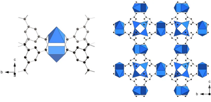
[image:19.595.102.488.226.430.2]The aluminium methylphosphonates AlMePO-α and AlMePO-β structures (Figure 1.5) reported by Maeda and co-workers42,43 were an early example of aluminium organophosphonates and were shown to demonstrate porosity comparable to zeolites such as ZSM-5.44
Figure 1.5: Structure of the AlMePO-α (left) and AlMePO-β (right) viewed down the pore channel, parallel to the c-axis in both cases. Aluminium polyhedral are shown in blue, bark blue for octahedral and light blue for tetrahedral coordination. Phosphonate tetrahedra are shown in orange and pink spheres represent the hydrogen atoms of the methylphosphonate.
AlMePO-β is prepared via a hydrothermal route to produce large crystals, which can be transformed to AlMePO-α by heating in a nitrogen stream saturated with water vapour at 500°C. The internal surfaces of the channels in the AlMePO materials differ from aluminophosphates, being hydrophobic due to the –CH3groups lining the walls.
Chapter 1 Introduction
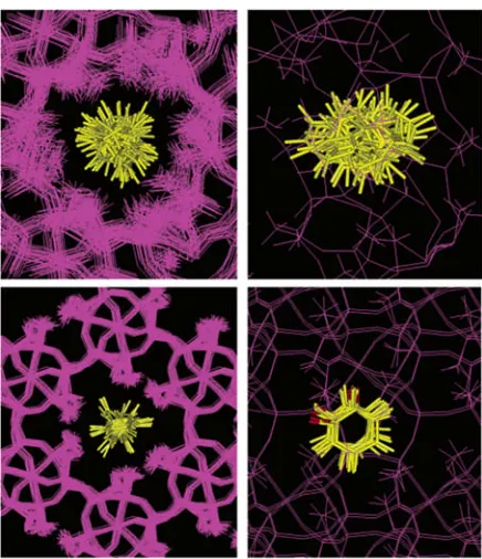
related sites on the pore. Toluene however is unable to tumble freely and is thought of as rotating in a cone around the para-axis of the molecule. These data were combined with molecular dynamics simulations to approximate the motion of the dosed molecules within the system (Figure 1.6).45 A subsequent study by Herdes et al. on AlMePO-α investigated the selective adsorption of ethyl chloride from a mixture with vinyl chloride on the same material.46
Figure 1.6: Trajectory of benzene molecules within the pores of AlMePO-β (above) and AlMePO-α (below). The structure is viewed along the channel axes (left) and perpendicular to these axes (right). The location of benzene in AlMePO-β is shown every 2.5 × 10⁻¹²s for the full length of the 1 × 10⁻¹⁰s simulation. The location of benzene in AlMePO-α is shown every 5 x 10-12s during the full 1 x 10
-10 of the simulation. The orthogonal view of the motion of benzene in AlMePO-α
[image:20.595.188.406.231.484.2]Chapter 1 Introduction
9
1.3.2 Metal Bisphosphonates
The next major development in phosphonate-based systems, following the interest in methylphosphonates, was to connect two phosphonate groups with an organic molecule, extending the building unit. This can range from a simple methylene group to a phenyl ring or more complex multi-ring systems such as those shown in Figure 1.7.47
Figure 1.7: Examples of simple bisphosphonate molecules
This organic linkage in the framework reduces the thermal stability of the resulting framework but allows for greater control of the internal surfaces as well as the potential for greater and more accessible porosity. Simple organic synthesis can be used to add functional groups to the linker molecules, such as amino and nitro groups, thus modifying the properties for applications such as gas adsorption.21
The piperazine-derived family of bisphosphonate ligands has been particularly successful in the preparation of porous frameworks.24,48 Of particular interest to this study are the piperazinebis(methylenephosphonic acid) and the 2-methylpiperazine and 2,5-dimethylpiperazine derivatives shown in Figure 1.8.
Figure 1.8: Piperazine-bis(methylenephosphonic acid) linker (H4L) (left), the
2-methyl-piperazine derivative (H4L’) (middle) and the 2,5-dimethyl- derivative
Chapter 1 Introduction
The first large pore framework reported with the piperazine-based linker (H4L) was the
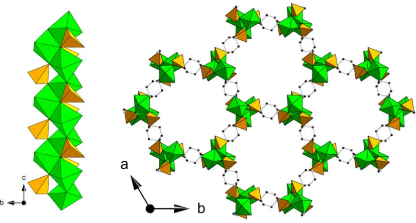
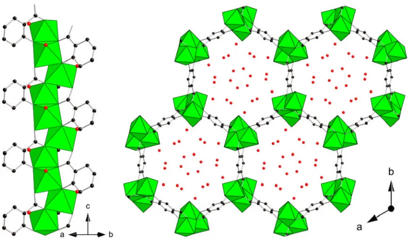
phosphonate STA-12(Ni) (Figure 1.9).24,49The framework is composed of helical chains
[image:22.595.88.502.267.489.2]of edge sharing nickel octahedra together with the phosphonate tetrahedra from the bisphosphonate linker. The resulting inorganic chains are bridged through the piperazine-based bisphosphonate to three other chains creating a honeycomb like array of unidirectional channels. The hexagonal channels have a cross-sectional diameter of 9 Å which in the as-synthesised state are filled with physisorbed water.
Figure 1.9: Helical nickel phosphonate chains (left) and hexagonal channels
(right) of the STA-12(Ni) framework. Nickel octahedra are shown in green and phosphonate tetrahedra are shown in orange, black spheres represent the carbon atoms of the organic linker
STA-Chapter 1 Introduction
11
The isoreticular analogue of the STA-12 framework topology was later prepared with the extended bipiperidine derivative of the bisphosphonate linker.25 This structure, STA-16 (Figure 1.10), shows an increased pore diameter of 18 Å (from 9 Å in STA-12) and is the largest pore size reported in metal phosphonate systems.
Figure 1.10: Comparison of the ligand and pore size in the 12(Co) And STA-16(Co) structures.25 Cobalt octahedra are shown in purple and phosphonate tetrahedra are shown in orange, black and pink spheres represent the carbon and hydrogen atoms of the organic linker.
Nitrogen adsorption data on STA-16, combined with non-local DFT calculations for N2
at 77 K show that the permanent porosity of the material can be represented by a cylindrical pore of diameter 18.5 Å approaching that of the mesoporous regime (20-500 Å).25Indeed the N
2adsorption isotherm shows an inflection at low pressure (0.025
p/p0) indicative of the capillary condensation observed in mesoporous materials. The
Chapter 1 Introduction
1.4 Carboxylate MOFs
1.4.1 Divalent Carboxylates
The divalent metal carboxylate based frameworks MOF-5 and HKUST-1 are examples of prototypical MOF materials and triggered a huge growth in the field of metal-organic frameworks. A keyword search for “metal-metal-organic frameworks” registers >1,600 publications in 2010 and >2,000 for 2011, a strong indication of the worldwide interest in this area and indicates that the growth is continuing. More recent work on divalent carboxylates with longer and more complex organic components is pushing the limits of gas adsorption and storage properties with the highest surface areas and lowest densities of all known crystalline materials.
1.4.1.1 MOF-5 & MOF-177
MOF-5 is an early and heavily studied example of a MOF material.32The material is an
example of a cubic 3-dimensional extended lattice composed of Zn4O inorganic
clusters connected by terephthalate linkers (Figure 1.11).
Figure 1.11: MOF-5 assembly, Zn4O(CO2)6 cluster (left), octahedral geometry of
terephthalate molecules(middle)and 3D cubic lattice(right). Zinc tetrahedra are shown in blue. Black spheres represent the carbon atoms of the organic linker
Chapter 1 Introduction
13
surface area (a monolayer-equivalent surface area) is stated to be of the order of 3000 m2g-1, significantly higher than that of most zeolites and at the time, among the highest of all known materials. One downside to the large open pore structure is the potential for interpenetration of 2 frameworks. In the case of MOF-5 and the IRMOF family of isoreticular structures31(see Figure 1.3 above), if the pore size is sufficient to contain a Zn4O cluster and the dicarboxylate is of sufficient length, then the formation
of a second extended lattice can occur within the first. This interpenetration or catenation of two frameworks results in a significant reduction in the porosity as the majority of the void space in the cage is filled with the other framework. Examples of interpenetration are reported for some members of the IRMOF series as shown in Figure 1.12.31
Figure 1.12: Interpenetration of the low density cubic lattices in IRMOF-13 (left) and IRMOF-15 (right).31
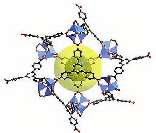
MOF -177 is another example of a MOF material containing the tetrahedral Zn4O
Chapter 1 Introduction
Figure 1.13: Single cage from the zinc carboxylate, MOF-177.33
MOF-177 has been shown to have the one of the largest surface areas of known materials to date (Figure 1.13). Literature states a Langmuir surface area value of 4500 m2g-1 with N2 adsorption giving a type I isotherm with adsorption of 1350 mg g-1
between 0.4 and 1 P/P0.50 These values show that MOF-177 is a highly porous open
framework MOF material with a 3-dimensionally connected array of porous cages.
1.4.1.2 HKUST-1
HKUST-1 is another early example of a divalent carboxylate MOF (Figure 1.14).51
Chapter 1 Introduction
[image:27.595.89.506.84.286.2]15
Figure 1.14: Individual Cu2(CO2)4(H2O)2 ‘paddlewheel’ cluster coordinated by
trimesic acid (left) and the porous cubic framework (right) of HKUST-1.51 Blue polyhedra represent the square pyramidal CuO5. Black spheres represent the
carbon atoms of the organic linker
The rigid, porous structure of the HKUST-1 framework combined with the accessibility of the activated metal sites upon dehydration has led to a lot of interest in adsorption, separation and catalysis applications.52-54
1.4.2 High surface area materials
Chapter 1 Introduction
Figure 1.15: MOFs with ultrahigh porosity: NOTT-11255 (left) and MOF-20054
(right)
1.4.2.1 CPO-27 / MOF-74
While surface area and pore volume is important to the adsorption properties of MOF materials, another consideration is the availability of coordinatively unsaturated metals sites. The divalent metal carboxylate CPO-27(M) (where M = Co,Ni) was reported by Dietzel and co-workers,57 while at a similar time work by Rosi et. al.
produced the isostructural zinc analogue, referred to as MOF-74.58The divalent metal and 2,5-dihydroxyterephthalic acid linker form a honeycomb like array of hexagonal channels (Figure 1.16). The inorganic component is a helical chain of edge sharing NiO6
Chapter 1 Introduction
[image:29.595.108.520.82.326.2]17
Figure 1.16: Single chain (left) and view along the hexagonal channels (right) of the nickel dihydroxyterephthalate, CPO-27(Ni).57 Nickel octahedra are shown in green, black spheres represent the carbon atoms of the organic linker and red spheres the oxygen of adsorbed water molecules.
Chapter 1 Introduction
1.4.3 Trivalent Carboxylates
Some of the most widely studied of all metal organic frameworks are trivalent metal carboxylate materials. Extensive work in this area has provided an understanding of the crystal chemistry of a wide variety of the trivalent first row transition metals
1.4.3.1 MIL-47 & MIL-53
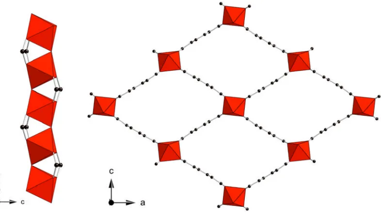
The vanadium terephthalate MIL-47, first reported by Barthelet and co-workers,62is an
example of a metal organic framework consisting of infinite corner sharing metal chains of VO6 octahedra bridged by the linear terephthalate organic linker. This
[image:30.595.109.502.321.542.2]connectivity results in the formation of large diamond shaped channels, as shown in Figure 1.17.
Figure 1.17: Corner sharing vanadium chains (left) and view along the rhombic channels (right) of the vanadium terephthalate, MIL-47(V).62 Vanadium octahedra are shown in red, black spheres represent the carbon atoms of the organic linker.
Chapter 1 Introduction
19
temperature under ambient pressure, as the channels are hydrophobic, being lined with phenyl rings and with no accessible metal sites or favourable hydrogen bonding positions the channels are hydrophobic.
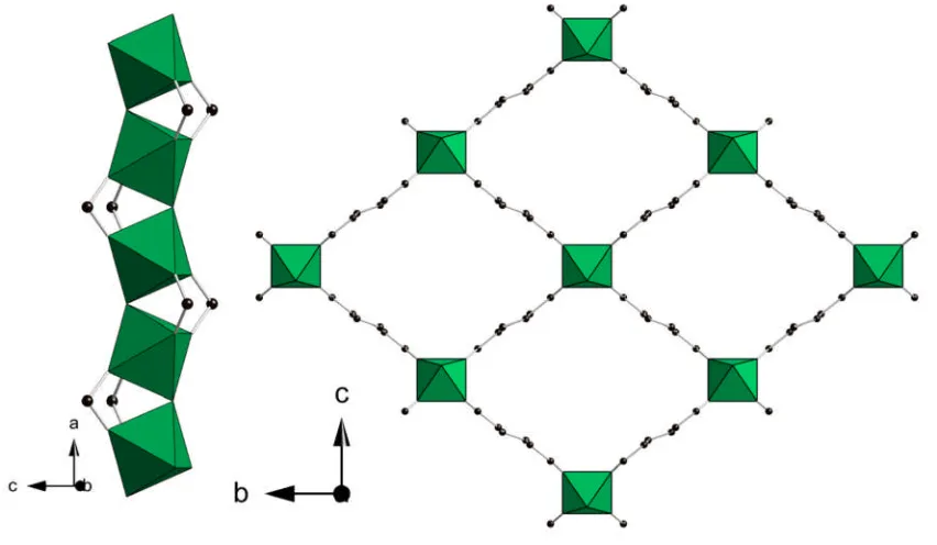
[image:31.595.98.524.302.550.2]MIL-53 was first reported with chromium29 (Cr3+) and shortly after with aluminium63 (Al3+) with terephthalic acid as the linker. 53 (Figure 1.18) is isostructural with MIL-47, the main difference is that MIL-53 only contains the trivalent metal and a μ2 -hydroxide bridge whereas the activated MIL-47 is the tetravalent V4+ with μ2-oxo bridging. As the activated form of the MIL-53 contains the metal hydroxide chains, the channels are hydrophilic with the hydroxide protons available for hydrogen bonding.
Figure 1.18: Corner sharing chromium hydroxide chains (left) and large pore (dehydrated) framework of MIL-53(Cr) (right). Chromium octahedra are shown in green, black spheres represent the carbon atoms of the organic linker.
When activated MIL-53(Cr or Al) is exposed to moisture, X-ray diffraction shows the material adopts a ‘closed’ structure, due to the strong hydrogen bonding interaction between the hydroxyl groups of the inorganic chains and the adsorbed water molecules.63As a result of this hydration behavior, the unit cell volume reduces by ~30
Chapter 1 Introduction
Figure 1.19: MIL-53(Cr) in the hydrated (narrow pore) state (left) and in the dehydrated (large pore) state (right). Chromium octahedra are shown in green, black spheres represent the carbon atoms of the organic linker.
Since the initial reports of the chromium and aluminium MIL-53, extensive work has been undertaken in this area, and the range of MIL-53 materials now extends to: Cr3+, Al3+, Fe3+, Ga3+, In3+, and (as a result of this work) Sc3+). The major developments in understanding the breathing and flexibility of the MIL-53(M) as well as the synthesis and characterization of MIL-53(Sc) will be discussed in detail in Chapter 6.
1.4.3.2 MIL-68
Work by Barthelet and co-workers also identified MIL-68, another trivalent metal terephthalate (Figure 1.20).64 The framework is a polymorph of the MIL-47/MIL-53 structure with the chemical formula, MIIIOH(CO
2-C6H4-CO2) initially reported for V3+
and later with In3+ and Ga3+. In this case the metal hydroxide chains connect to form
Chapter 1 Introduction
[image:33.595.107.520.82.300.2]21
Figure 1.20: Corner sharing vanadium chains (left) and large pore framework of MIL-68(V) (right). 64 Vanadium octahedra are shown in red, black spheres
represent the carbon atoms of the organic linker.
N,N’-Dimethylformamide (DMF) solvent molecules were observed in the smaller triangular channels of as-prepared MIL-68(In) reported by Volkringer et. al,65
disordered over two positions, with hydrogen bonding between the oxygen of the DMF and the hydroxyl group of the inorganic chain. The solvent was removed by calcination at 200°C overnight in a furnace. The activated samples were stored under inert atmosphere to prevent rehydration which would lead to hydrolysis and ultimately decomposition of the structure. Adsorption studies on the indium and gallium forms of MIL-68 give a value for the BET surface area of 1117(24) m2 g-1,
746(31) m2g-1 and 603(22) m2g-1 for the gallium, indium and vanadium forms
Chapter 1 Introduction
1.4.3.3 MIL-88
[image:34.595.216.380.222.385.2]Further study on the metal carboxylate systems of trivalent iron and chromium yielded a series of materials referred to as MIL-88(A-D). First reported as an iron fumarate,66 and based on the trimeric building unit (Figure 1.21) obtained on the crystallization of iron (and chromium) acetate, MIL-88 is a family of isoreticular materials prepared with dicarboxylate linkers.67
Figure 1.21: Iron trimer unit with bridging trifluoroacetate anions. Iron octahedra are shown in brown, black and green spheres represent the carbon and fluorine atoms of the organic linker respectively.
Chapter 1 Introduction
23
[image:35.595.119.480.171.417.2]hydroxide or fluoride (depending on the synthesis conditions) occupying one of the unsaturated metal sites and the other two could be water or exchanged solvent species.
Figure 1.22: MIL-88(Fe or Cr) series with the fumarate, terephthalate, naphthalate and biphenyldicarboxylate linkers respectively.67
Chapter 1 Introduction
Figure 1.23: Open and closed MIL-88(Fe or Cr)67
1.4.3.4 MIL-100 & MIL-101
MIL-100 and MIL-101 comprise the same trimeric building unit as the MIL-88 (above).68-70The rigid carboxylate linkers connect trimers such that they form a super-tetrahedra which is the main building unit of the material (Figure 1.24). The difference between the two structures is that the MIL-10070is prepared with trimesic acid where the super-tetrahedral unit has a trimesate on the face of each tetrahedra whereas, the MIL-10168 is prepared with terephthalic acid and consists of tetrahedra with a
[image:36.595.133.463.84.327.2]Chapter 1 Introduction
25
The two structures share the same overall network connectivity of tetrahedral units, in zeolite nomenclature the MTN topology, a framework type reported for the zeolite ZSM-3971 where the AlO
4 and SiO4 tetrahedra are replaced by ‘super-tetrahedral’
building units. The difference in size between the metal tetrahedra of ZSM-39 and the super-tetrahedral unit of the MIL-100 and MIL-101 means that the pore size is also significantly larger. The structures contain two types of cage with porosity into the mesoporous region. The internal diameter of the cages in MIL-101(Cr) is 29 Å for the smaller cage and 34 Å for the larger. The smaller cage is accessible through microporous pentagonal windows with a cross-sectional diameter of 1.2 nm, and the larger cage through both the pentagonal windows and larger hexagonal windows of diameter 1.6 nm (Figure 1.25).
Figure 1.25: ‘Windows’ between cages in the MIL-101(Cr) structure. Metal octahedra are shown in pink, black spheres represent the carbon atoms of the organic linker.
The MIL-101 structure is best represented by comparison to the zeolitic MTN network (Figure 1.26), a framework type reported for the zeolite ZSM-39. Where the zeolite contains AlO4and SiO4 tetrahedra, in MIL-101(Sc) these are replaced my much larger
Chapter 1 Introduction
Figure 1.26: MTN network with a single smaller cage (blue) and larger cage (red) identified. Each vertex represents the centre of a tetrahedral unit, either an AlO4
[image:38.595.146.446.82.315.2]or SiO4tetrahedra in ZSM-39 or the super-tetrahedral building unit of MIL-101.
Figure 1.27: Tetrahedral units from the ZSM-39 zeolite and MIL-101(Cr) MOF which share the MTN topology. Metal octahedra are shown in pink, black spheres represent the carbon atoms of the organic linker.
Chapter 1 Introduction
27
in the synthesis) to balance the charge on the framework. The remaining two sites are occupied by H2O molecule, as evidenced by IR studies of the material.72 Removal of
these terminal H2O molecules results in the formation of Lewis acidic free metal sites.
The MIL-101 structure requires multi-stage activation to render the full volume accessible. Terephthalic acid molecules from the original synthesis can become trapped in the cages and must be removed. There are various activation methods reported for the material but the most effective involves first treating the material in hot ethanol for 8 hours followed by dispersion in aqueous ammonium fluoride and washing in hot water.4 Following this activation, the BET surface area of the MIL-101(Cr) is reported at 4230 m2g-1. Recent work on MIL-101(Cr) has explored a range of applications including the incorporation of catalytically active species such as polyoxometalates73 within the cages and also the use of MIL-101 in the chromatographic separations of substituted aromatics.74
1.4.4 Framework flexibility in MOFs
Flexiblility in MOF systems typically refers to reversible crystal-to-crystal transitions where the framework connectivity of the bulk material is retained but a change occurs in the geometry of the framework components.12This could be as simple as a
rotation within an organic molecule (changing the internal surface with minimal volume change) or as complex as a 3-dimensional hinging motion increasing the overall unit cell volume. This type of flexibility is not unique to MOF systems. Some zeolite frameworks are known to have a degree of flexibility, typically arising from exchanging out the cations which stabilize certain framework components such as ring systems between cages. A good example of this flexibility is observed in the zeolite-rho structure.75
Chapter 1 Introduction
where the void space and 3D connectivity is such that two fully connected frameworks can exist within each other. In materials such as MOF-50876 and some
members of the IRMOF series discussed earlier (Figure 1.3), there can be translation of one framework with respect to the other, again driven by the adsorption of gas or solvent molecules. The final example shown (D) is representative of a case where the flexibility arises from rotational flexibility of the organic ligand pillaring the layers.26In this case rigid layers are separated by the flexible linker which can expand and contract in response to the adsorption and desorption of guest molecules.
Figure 1.28: Schematic representation of the modes of flexibility observed in MOF structures.
1.4.5 Scandium Chemistry and MOF synthesis
1.4.5.1 General scandium chemistry
The existence of scandium as an element was first proposed by Dimitri Mendeleev when he created the periodic table and predicted the presence of an element that he proposed would resemble boron in it properties and he called it ekaboron. Scandium oxide was isolated by Swedish mineralogist Lars Frederick Nilson in 1876 from euxenite and gadolinite minerals from scandanivia, the name scandium derives from the latin
Chapter 1 Introduction
29
and results in a stronger alloy without the need for rivets although it is still more expensive than titanium alloys currently in use.
The chemical behaviour of scandium is similar to that of aluminium and yttrium. Naturally occurring scandium is exclusively the45Sc isotope a quadrupolar nuclei which has a nuclear spin of 7/2. A major advantage of this is that it permits the use of solid-state NMR analysis of scandium materials, providing information on the local structure of the solids.
In organic chemistry, scandium triflate is commonly used as a Lewis acid catalyst, prepared by reaction of scandium oxide with trifluoromethanesulfonic acid (referred to as triflic acid).77,78 This is used as a recyclable, homogenous, Lewis acid catalyst, which unlike most common Lewis acidic compounds, is not deactivated in the presence of water.77 In terms of ionic radius, scandium sits between indium and the first row transition metals.79
Extensive literature studies have been conducted on the other trivalent metals in the exploratory synthesis of novel MOFs, yielding a wide range of framework topologies. Scandium, being towards the larger and lighter end of the scale, presents as an excellent choice of trivalent ion for MOF synthesis (Figure 1.29).
Figure 1.29: Comparison of the ionic radii of trivalent metals commonly used in carboxylate MOF syntheses.
1.4.5.2 Scandium in porous materials
Chapter 1 Introduction
(1,4,7,10-tetraazacyclododecane) resulting in a cubic arrangement of interconnected cages. At a similar time, the work of Riou et. al. in Versailles yielded an ethylenediammonium templated scandium phosphate (Figure 1.30).81 This material,
solved using single-crystal X-ray diffraction and solid-state NMR, is composed of corner shared ScO6octahedra and HPO4tetrahedra formed around the ethylenediammoniun
organic template.
Figure 1.30: The first scandium based open framework materials. The scandium sulphate phosphate of Bullet al.80(left) and scandium phosphate of Riouet al.81
(right). Scandium octahedra are shown in pink, sulphate tetrahedra in green and phosphonate tetrahedra in orange. Black, green and pink spheres represent the carbon, nitrogen and hydrogen atoms of the organic structure directing agent respectively.
Chapter 1 Introduction
31
1.4.5.3 Scandium MOFs
Prior to this work there were few reports of scandium containing metal-organic frameworks. The first scandium based metal-organic framework was reported by Perles et al.82 The framework is composed of layers of Sc2O11 corner sharing dimers
[image:43.595.192.403.195.432.2]separated by the dicarboxylate linker succinic acid (O2CC2H4CO2) shown in Figure 1.31.
Figure 1.31: The first scandium MOF, a scandium succinate reported by Perleset al.82Scandium octahedra are shown in pink, black spheres represent the carbon atoms of the organic linker.
Although not permanently porous, catalytic studies showed that the scandium succinate was active in the Friedel-Crafts acylation of anisol (with acetic anhydride, 30 % yield after 24 hours) and the reaction of benzaldehyde with trimethyl orthoformate, (70 % yield after 4 hours) producing the dimethyl acetyl. Thermogravimetric analysis of the materials showed thermal stability of over 500°C under nitrogen gas. This represents a high thermal stability for an organic bearing framework and is representative of the strong scandium – oxygen bonds.
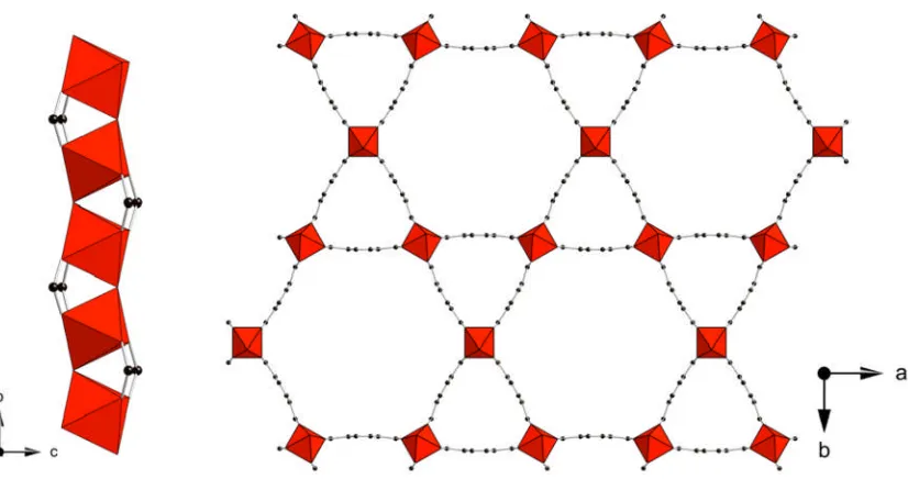
The first reporting of a permanently porous scandium based MOF was the scandium terephthalate Sc2BDC3.27 The structure is composed of chains of octahedral Sc3+
Chapter 1 Introduction
[image:44.595.106.499.184.435.2]means that each chain is connected to six adjacent chains creating an array of microporous triangular channels, each delimited by the phenyl rings of the terephthalate linker. The fully coordinated metal centres and the strong Sc-O bonds result in high thermal stability in metal-organic framework materials.
Figure 1.32: The small pore terephthalate Sc2BDC3 showing a single chain (left)
and viewed down the triangular channels (right). Scandium octahedra are shown in pink, black spheres represent the carbon atoms of the organic linker.
Single crystal diffraction studies on Sc2BDC3, reported by Miller et. al,83 describe in
detail the structural response of the framework to adsorption of carbon dioxide and fuel related gases. The small microporous channels along with the hydrophobic nature of the pore surface make Sc2BDC3an interesting candidate for separation experiments
and will be discussed further in Chapter 5.
Chapter 1 Introduction
33
crystallinity at this temperature point - with only 002 and 004 reflections observable. Although the framework topology suggests that there should be significant porosity, attempts to access the porosity with nitrogen gas at 77 K were unsuccessful. The structure was solved by single-crystal X-ray diffraction.
Chapter 1 Introduction
1.5 Column Chromatography
To date there are very few commercial applications known for MOF materials. One application where MOF materials could offer advantages over conventional materials is in chromatographic separations. MOFs offer many potential benefits over the current industrial standard including a tunable organic pore surface, large range of pore sizes and lower activation temperatures. The organic functionality can determine if a pore cavity is hydrophilic or hydrophobic, chiral or achiral and in the case of MOFs with sufficient pore size, molecules can be grafted onto the framework post-synthetically to modify the behaviour.
1.5.1 MOF-508
Prior to this work there was limited literature on the use of MOFs in chromatography. The first example of a MOF used in gas chromatography (GC) was a zinc based amine carboxylate, with the formula Zn(BDC)(4,4’-Bipy)0.5 referred to as MOF-508.76 The
Chapter 1 Introduction
[image:47.595.160.439.426.659.2]35
Figure 1.34: Structure of MOF-508a (left) and MOF-508b (right) showing the flexibility in the structure with the two interpenetrating networks coloured red and green76
This material was investigated in the separation of natural gas mixtures, linear alkanes and of linear-branched alkane mixtures. The experiment used a packed column, 120 cm long, containing 3 g of MOF-508 crystals ranging in size from 25-100 μm. The GC equipment used helium as the carrier gas at 60 psi and a temperature range of 40-150°C. The column was effective in the separations reported as shown in Figure 1.35.76
Chapter 1 Introduction
The small pore channels of the MOF-508 structure and the van der Waals interactions with the pore wall are stated to be the main contributors to the observed retention times, with pore channels accessible only to the linear parts of the alkane and not the branched sections.
Although the separations measured for this material were successful, the flexibility and interpenetration observed in the structure could lead to problems, both in manufacturing and under use in the GC environment. As the active structure is stated to be the open form MOF-508a, with narrow linear channels lined with phenyl rings, a more rigid framework with similar pore chemistry could be a more suitable candidate.
1.5.2 MIL-47
Another significant example of MOFs in chromatography is the use of MIL-47(V) in the separation of xylene isomers reported by Alaerts et. al.85The separation ofpara-xylene
meta-xylene and ethylbenzene is a challenging separation currently utilising ion exchanged zeolite X and Y. Before testing MIL-47(V) in a column experiment, the selectivities for three candidate materials were determined from bulk measurements of uptake from binary mixtures in batch experiments. These included 47(V), MIL-53(Al) and Cu3(BTC)2. From these results, MIL-47(V) showed the most promising results
Chapter 1 Introduction
[image:49.595.203.396.89.267.2]37
Figure 1.36: Chromatographic separation of a mixture of ethylbenzene, meta-xylene, and para-xylene on a column packed with MIL-47(V) in the liquid phase, with hexane as the desorbent at 298 K. The signal intensity of the refractive index detector is shown versus the eluted volume.85
The high selectivity could not be explained by the difference in interaction energies between the different components, as zero coverage adsorption enthalpies measured in the gas phase were reported as being identical. Instead, the packing of molecules in the structure was found to be the critical difference leading to the observed selectivity. For example, para-xylene, which eluted last in the experiment, was found to have a more efficient packing in the sterically restricted channels with strong π-π interactions between adsorbed para-xylene molecules. Positions for each of the molecules in the MIL-47(V) structure were identified by Rietveld refinement of X-ray powder diffraction data on the solids saturated with the relevant aromatic species.
1.5.3 MIL-101
Chapter 1 Introduction
leaving a thin film of the microcrystalline particles as a coating, SEM images of this coating are shown in Figure 1.37.
Figure 1.37: SEM images of the cross-section of the column (left) and the MIL-101 deposited on the inner surface of the capillary.74
The column showed well resolved, baseline separated peaks with theoretical plates calculated to be 3800 plates m-1(Figure 1.38). The GC trace was collected on a 15 m × 0.53 mm (internal diameter) column at 160°C under a nitrogen flow of 3 mLmin-1. Also of interest is that only 1 mg of MIL-101 was used in the preparation of the column.
Figure 1.38: GC separation of xylene isomers and ethylbenzene on a MIL-101 coated capillary column (15 m long 0.53 mm i.d.) at 160°C under a N2flow rate
Chapter 1 Introduction
39
1.5.4 Column summary
Chapter 1 Introduction
1.6 Aims
The principal aim of this work was to investigate the effects of structural flexibility and functionalization on the adsorption and separation properties of metal-organic framework materials.
The work focused on two classes of materials, phosphonates and scandium carboxylates where the synthesis of novel scandium carboxylates and functionalisation of novel and existing materials was the major area of the research.
Novel materials were characterized using X-ray diffraction, solid-state NMR, chemical analysis (CHNS) and thermogravimetric analysis (TGA). Porosity of the materials was characterized by nitrogen and carbon dioxide adsorption to determine optimal weight percent mass uptake and surface area including both volumetric and gravimetric analysis techniques.
Chapter 2 Experimental Methods
41
Chapter 2 Experimental Methods
2.1 Synthesis Methods
Materials in this work were synthesised via a hydrothermal or solvothermal route. The starting mixture consisted of a metal oxide or salt, organic ligand and any structure-directing agents (SDA), dissolved or dispersed in solvent. The mixtures were stirred thoroughly, transferred to a PTFE lined stainless steel autoclave (examples of which are shown in Figure 2.1), sealed and heated in an oven. The products were filtered and washed with solvent (typically the solvent used in the synthesis) and dried at 50 °C in a drying oven. Exceptions to this were when the solvent used was a high boiling point organic solvent such as N,N’-Dimethylformamide (DMF). The solid products were washed thoroughly with ethanol after filtration or stirred in an excess of the solvent to exchange any solvent coordinating to the metal sites.
Figure 2.1 Example of autoclaves used in this study. The Parr type, 23 mL autoclave (left) and a 40 mL autoclave made in-house (right).
poly-Chapter 2 Experimental Methods
43
the behavior and to understand the flexibility or response to solvent exchange or desolvation.
2.2 Characterisation of Materials
2.2.1 X-ray Diffraction
[image:55.595.194.399.393.619.2]X-ray diffraction (XRD) is the principal technique for obtaining information on long range order within crystalline framework materials. A crystal is a solid consisting of a three dimensional periodic array of atoms or molecules. The array of equivalent points or lattice points of a crystalline solid can be represented by a repeat unit known as a unit cell (Figure 2.2). A unit cell can in turn be described by a combination of an asymmetric unit, the minimum set of atoms required to produce the full structure, and the symmetry elements of a space group. Any plane of lattice points can be described using the Miller indices (hkl) where the plane described is orthogonal to the direction (h,k,l).
Figure 2.2 The unit cell with lengths a,b,c and angles α, β, γ
Chapter 2 Experimental Methods
point in the centre of the cell. Single face centering (A, B or C) where there are lattice points on the cell corners and an additional point in the centre of one face; Face-centering (F) with lattice points on the cell corners and one additional point at the centre of each face. This would give a total of 42 lattice types (seven crystal systems each with six lattice centering options) but as a number of these are equivalent to each other, the result is 14 distinct lattices referred to as Bravais lattices (Table 2.1).
Lattice Systems Defined by 14 Bravais lattices
Triclinic ܽ≠ܾ≠ܿ; ߙ≠ߚ≠ߛ P
Monoclinic ܽ≠ܾ≠ܿ; ߙ=ߛ= 90°≠ߚ P C Orthorhombic ܽ≠ܾ≠ܿ; ߙ=ߚ=ߛ= 90° P C I F Tetragonal ܽ=ܾ≠ܿ; ߙ=ߚ=ߛ= 90° P I Rhombohedral ܽ=ܾ=ܿ; ߙ=ߚ=ߛ≠90° P Hexgonal ܽ=ܾ≠ܿ; ߙ=ߚ= 90°ߛ= 120° P
Cubic ܽ=ܾ=ܿ; ߙ=ߚ=ߛ= 90° P I F
Table 2.1: The 7 lattice systems and the associated Bravais lattices.
Thirty two point groups, sets of symmetry operations comprising mirror planes, rota-tions, translations and inversions, when applied to an atom or group of atoms, produce the unit cell. The combination of the Bravais lattice and the point group gives what is referred to as the space group of a given material. There are a total of 230 unique space groups which can be used to represent a crystal structure.
Chapter 2 Experimental Methods
45
2.2.1.1 Single Crystal X-ray Diffraction
The concept of X-ray diffraction by crystals was originally proposed by Max von Laue (who conducted the first experiments) and later developed by William and Laurence Bragg. In X-ray diffraction a regular array of identical lattice planes in a crystalline solid act as a diffraction grating and the observed scattering of the incident X-rays occurs constructively where the path length difference is equal to an integer number of wavelengths, as described by Bragg’s law (a schematic representation is shown in Figure 2.3).
nλ = 2d sin θ
(1)Constructive interference occurs where the path difference is an integer number of wavelengths (AB + BC = nλ)
Figure 2.3: Schematic representation ofBragg’s law.
Chapter 2 Experimental Methods
series of images and indexing the spots to determine the unit cell dimensions and subsequently the space group. Once the space group is known, Fourier transforms are applied to the data to relate the intensity of the diffraction spots (I) to the structure factor (F):
I
୦୩୪∝ |F
୦୩୪|
ଶ (2)As the intensity is proportional to the square of the structure factor it means that the phase of (F) cannot be determined directly, this is commonly referred to as the ‘phase problem’. Experimental diffraction patterns represent scattering from parallel planes
(ℎ݈݇)and are dependent on the type and location of atoms within the unit cell(ݔݕݖ).
ܨ= ∑݂݁ଶగ(௫ା௬ା௭) (3)
Where݂is the atomic scattering factor for each atom(݊)
The scattering is further influenced by thermal vibration (or positional disorder) of atoms in the unit cell.
ܨ= ∑݂݁ଶగ(௫ା௬ା௭)∙݁
షఴഏమೆ ౩మഇ
ഊమ (4)
Where ܷ is the temperature factor of the atom, a measure of the displacement
around the point(ݔݕݖ)and can be isotropic (spherical) or anisotropic (elliptical).
To obtain a structure, the electron density at points in the cell must be calculated.
ߩ௫௬௭= ଵ∑|ܨ|݁ିଶగ(௫ା௬ା௭) (5)
Chapter 2 Experimental Methods
47
[image:59.595.124.480.245.621.2]crystallites and rotated in the X-ray beam during sample collection. The result of this process is that the sample can be thought of as an average of all possible orientations of the crystallites with respect to the X-ray beam and the diffraction images produced will therefore be an average of the series of spots that would be produced from a single crystal resulting in a series of diffraction cones attributable to the lattice vectors in reciprocal space. A schematic representation of single crystal and powder X-ray diffraction is shown in Figure 2.4.
Figure 2.4: Schematic of single crystal and powder X-ray diffraction.
Chapter 2 Experimental Methods
crystals, ensures the crystal analysed is representative of the bulk phase. As a result of the averaging of the diffraction spots into cones, it is more difficult to obtain phases from the powder X-ray diffraction patterns making the structure solution much more challenging than from single crystal data.
[image:60.595.167.424.479.682.2]Chapter 2 Experimental Methods
49
Powder data was collected either in-house on a Stoe STADI/P diffractometer (an example of which is shown in Figure 2.5) in transmission mode with primary monochromation and Cu Kα1X-radiation or collected at a synchrotron facility such as
Diamond Light Source beamline I11 which is configured for high resolution powder diffraction. Samples were ground into fine powder to prevent preferred orientation effects and mounted between two Mylar discs or placed in a 0.5 mm or 0.7 mm quartz capillary. A typical X-ray powder diffraction pattern obtained from a Stoe STADI/P diffractometer is shown in Figure 2.5.
Single crystal data was collected on a Rigaku Mercury CCD diffractometer using monochromated Mo Kα radiation or the ACTOR SM automated system utilising a sealed tube X-ray source and a CCD detector.
2.2.2 Rietveld Refinement and Le-Bail method
As well as using powder X-ray diffraction as a screening tool, it is also possible to use the data to evaluate a structural model. Rietveld refinement is a technique used to relate a structural model to experimentally obtained diffraction data (neutron and/or powder X-ray diffraction data). As the Rietveld method requires a starting structural model, preferable in reasonably good agreement with the experimental data, it is a refinement technique rather than a structure solution method. Structural models for Rietveld refinement in this study were primarily obtained by modifying a literature structural model (of a similar material) or directly from a single-crystal structure solution in the case of bulk phase analysis.
It is often advisable to use the Le-Bail method of unit cell refinement prior to the Rietveld analysis. The Le-Bail method is independent of the unit cell contents and is used to determine if it is possible to fit the diffraction pattern using only the unit cell and symmetry proposed for the model. As the difference between an experimental diffraction pattern and a pattern calculated from the model is based on the full diffraction pattern calculation, it is important to start with a model where the unit cell and symmetry is as close to the experimental pattern as possible.
Chapter 2 Experimental Methods
an experimental diffraction pattern and a calculated pattern.
ܯ = ∑ݓ(ܫ−ܫ)ଶ (6)
Whereܫandܫare the observed and calculated intensities. The weighting ݓ is based
on the calculated errors for each reflection and the sum is over the full data set.
The main statistics reported for how well the data matches the model are the reduced
߯ଶ,RpandRwp.
߯ଶ= ெ
(ே್ೞିேೡೌೝ) (7)
HereNobsis the total number of observations in the pattern and theNvar is the number of variables in the least squares refinement and the optimum value for ߯ଶis 1.0. Rp
andRwp are the calculated residuals, again a measure of the difference between the calculated and experimental pattern with the value tending to zero as the refinement fit improves.
ܴ = ∑|ܫ∑−ܫܫ|
and
ܴ௪ = ඨ∑ܯݓܫ ଶ
2.2.3 NMR
in-Chapter 2 Experimental Methods
51
NMR works on the principle that nuclei with a non-zero nuclear spin possess nuclear spin (I) and angular momentum (P) generating an associated (non-zero) magnetic moment (μ)
μ = γP (8)
Whereߛis the gyromagnetic ratio of the nucleus.
The nuclear spin quantum number (I) can be any multiple of ½ for ܫ Ͳcreating
ሺʹܫ ͳሻdiscrete values for the angular momentum.
Using hydrogen (1H) with one proton and spin I = ½ as an example, the magnetic moments arising from the spins can be thought of as individual magnets. These magnetic moments can be aligned (either parallel or anti-parallel) when an external magnetic field is applied. The lower energy state (spin state (x), Figure 2.6) will have a slight excess of spins relative to the higher energy state.
οܧ ൌ ߛܤ (9)
Whereℏis the reduced Planck’s constant andܤis the applied magnetic field.
Figure 2.6: Alignment of nuclear spins in the presence of an external magnetic field.
Chapter 2 Experimental Methods
߱ ൌ ߛܤ (10)
[image:64.595.220.382.121.316.2]Where߱is known as the Larmor frequency
Figure 2.7: Precession of a magnetic moment around the axis of the applied field.
The result is that the net magnetisation of a spin system under study can be thought of as a single magnetic moment, referred to as the bulk magnetisation vector (Figure 2.8),
ܯ, along the z-axis and parallel to the applied magnetic field (ܤ).
Figure 2.8: Bulk magnetization vector.
Radiofrequency (RF) pulses can be used to move the bulk magnetisation vector (Figure 2.9), ܯ, away from the z-axis. The extent to which it is moved is controlled by the
duration of the RF pulse. The angle,ߠ, through which the vector ܯmoves is related
Chapter 2 Experimental Methods
[image:65.595.204.393.76.271.2]53
Figure 2.9: Representation of the change in the bulk magnetization vector as a result of a radiofrequency pulse B1.
Following the RF pulse, the NMR signal is detected by means of an oscillating voltage in a coil surrounding the sample, upon relaxation from the excited state to the thermal equilibrium. Two main processes of relaxation are observed:
1: Longitudinal relaxation (T1): spin – also known as lattice relaxation or the decay
constant for repopulation of the energy levels to the thermal equilibrium level
2: Transverse relaxation (T2): also known as spin-spin relaxation or the decay constant
for the net bulk magnetisation vector in the x-y plane to return to zero.
The detected signal, free induction decay (FID) is Fourier transformed to produce the frequency spectrum of the signal known as the NMR spectrum.
2.2.3.1 Dipolar Broadening
Dipolar interactions are the interaction of a nuclear spin with the magnetic field of an adjacent nuclear spin. This through space interaction can result from heteronuclear or homonuclear species and is one effect responsible for broadening solid state NMR spectra. In solution, molecules experience continuous Brownian motion that results in an averaging of the dipolar interactions over the different orientations whereas in the solid state, if the sample is static, the spins couple resulting in a broad signal.
Dipolar coupling frequency
ܤ= ఓସగబఊೕఊೖℏ
ೕೖయ [1 − 3 cos
Chapter 2 Experimental Methods
Anisotropic dipolar interactions can be suppressed by rotating the sample around an axis, 54.74° to the applied magnetic field. At this angle, [1 − 3 cosଶߠ] = 0 and the
Chapter 2 Experimental Methods
55
2.2.3.2 Quadrupolar Interactions
[image:67.595.187.407.298.525.2]Nuclear spins with ܫ ͳȀʹ have a non-spherical charge distribution resulting in an electric quadrupole moment. The interaction of this quadrupolar moment with electric field gradients can lead to extremely broad lines in the NMR spectra but can also give useful information about the coordination environment around the species under study. The quadrupole interaction may be of the order of 10’s of MHz which is not insignificant compared to the Zeeman splitting of the order of 10-100’s of MHz (Figure 2.10).
Figure 2.10: Zeeman splitting and degeneracy of energy levels for a spin 5/2 nucleus.
The First order quadrupolar interaction can be averaged or minimized by increasing the spin rate of MAS and by increasing the magnetic field strength. Importantly, the central transition – indicated by the arrows in Figure 2.10 – is not influenced by the first order quadrupolar interaction and has the same magnitude as the Zeeman interaction. The satellite transitions are visible as broadening of the spectra or as spinning sidebands if the spectral lines are resolved. The second order quadrupolar interaction cannot be averaged to zero by MAS.
Chapter 2 Experimental Methods
[image:68.595.208.345.236.457.2]the second order quadrupolar interactions. One option is to use advanced rotor technology to spin the sample around two axes simultaneously known as double rotation (DOR) at the magic angle (54.74°) and at 30.54°. Another technique, dynamic angle spinning (DAS), uses sequential spinning at two different angles. The final method, and most relevant to this study, is Multiple Quantum Magic Angle Spinning (MQMAS). This technique uses pulse sequences to excite multiple quantum coherences such as triple quantum (3Q) and 5Q coherences (Figure 2.11).
Figure 2.11: Triple quantum excitation