Wireless Mobile Evolution to 4G Network
Mohammed Jaloun, Zouhair Guennoun
1Telecoms Engineer – Motorola, Morocco
2Laboratoire d’Electronique et de Communications – Rabat, Morocco
E-mail: [email protected], [email protected]
Received January 30, 2010; revised February 22, 2010; accepted February 24, 2010
Abstract
In this paper, we give an overview of the evolution of wireless mobiles starting from the first generation which is the analogue system started in 1980’s, and passing through the 2G technologies which are all digital networks and GSM is the most popular network. 2.5G networks will introduce the packet notion on the ex-isting 2G networks and 3G will bring the quality of service as new perspective for the 3G partnership projet 3GPP and 3GPP2. However, high demand on data speed has pushed the operators to looking for 3.5G system. 3.99G networks are defined as long-term evolution for the existing 3G network and it will be based on OFDM and MIMO technologies. 4G networks was not yet defined, but requirement is to support heteroge-neous networks at 100 Mbps mobility data speed.
Keywords: 4G, OFDM, MIMO
1. Introduction
Mobile networks have evolved through more than three generations, starting with the analogue or first-generation (1G) networks deployed in the early 1980s, and moving on to the digital second-generation (2G) networks de-ployed in the early 1990s. Operators started to deploy 3 G networks in 2001-03, and 3.5G networks from around 2005. Networks still in the design phase include 3.9G and 4G systems, which are expected to be deployed in the 2008-10 and 2010-20 timeframes, respectively.
The general principle behind this grouping is that mo-bile technologies are in the same generation if they have similar network characteristics and deployment time-lines.
The International Telecommunications Union (ITU), for example, uses a different approach when defining 3G, it groups technologies based on theoretical maximum connection speeds.
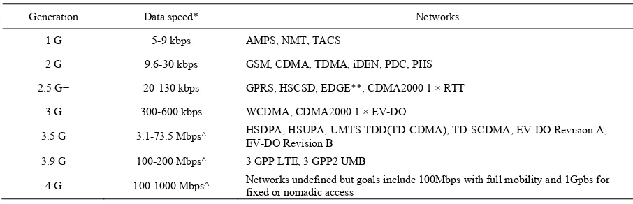
The Table 1 bellows classify networks by generation based on the speed offered:
Notes: WiMAX is classified separately as it has a dis-tinct evolution, but its current capabilities are similar to 3.5G and its core technologies will be used in 3.9G systems.
2. 1G Networks
The first cellular mobile phone systems were introduced in the early 1980s based on analogue standards. Ana-logue systems are in the process of being phased out, with 1.9 million subscribers worldwide at the end of 2006, down from 4.7 million at end-2005, as they are being superseded by digital networks.
The main analogue systems are:
1) Nordic Mobile Telephone (NMT) was the first operational analogue system in use and was originally introduced into the Nordic countries of Denmark, Finland, Norway and Sweden. NMT runs at 450 MHZ and 900 MHz, some NMT 450 networks are still in op-eration, mainly in Sweden, Russia and Eastern European countries, but most NMT 900 networks have now been closed.
each call, in contrast to other access technologies, which use different methods of dividing up the available spec-trum.
3) Total Access Communications System (TACS) is derived from AMPS and was introduced as the analogue standard for the UK operating at 900 MHz. Among oth-ers, it was also used in China and Japan, which intro-duced a Japanese Total Access Communications (JTAC) system operating between 800 MHz and 900 MHz ranges.
4) Cellular Digital Packet Data (CDPD) was speci-fied by a consortium of American cellular operators in 1993 and is based on IP overlaying an AMPS network. CDPD makes use of excess capacity on the AMPS net-work to provide packetised connections up to 19.2 kbps, although inherent data overheads reduce this to a practical operating data rate of around 10 kbps.
3. 2G Networks
The majority of mobile phone systems today are based on a number of digital technology networks, and their variants, as defined in Table 2 namely:
1) Global System for Mobile Communication (GSM) 2) Code Division Multiple Access (CDMA)
3) Time Division Multiple Access (TDMA) 4) Integrated Digital Enhanced Network (iDEN) 5) Personal Digital Cellular (PDC)
6) Personal Handyphone System (PHS).
The most important difference between 2G networks is the spectrum efficiency and the number of channels used as show in Figure 1.
For iden, TDMA and GSM the channel bandwidth is small, it is from 25 KHz for iDEN and TETRA to 1.25 MHz for CDMA.
Frequency reuse is technically used for TDMA net-works, contrarily to CDMA which use the entire spectrum and minimize the interference which allow 1 frequency reuse.
IDen use a small spectrum, because it utilizes a high modulation QAM 16 and QAM 64 and QPSK.
It is easier to understand 2G Digital networks if it we compared the different multiple access technologies.
Multiple Access Comparison – FDMA
FDMA is used for analog cellular, in this case each user is assigned a discreet slice of spectrum and each user uses 100% of the channel as show in Figure 2.
Multiple Access Comparison – TDMA
[image:2.595.69.522.428.574.2]In Figure 3, TDMA is used for both GSM and IS-54, Key point to note in case of TDMA is that the users are still assigned a discreet slice of RF spectrum, but in this case each RF carrier is further sub-divided into number of time slots, and multiple users sharing the same RF carrier. In case of GSM, 8 users simultaneously transmitting and receiving information on a single carrier, which is 200 KHz wide.
Table 1. Network generation.
Generation
Data Networksspeed*
1 G
5-9 kbps AMPS, NMT, TACS
2 G
9.6-30 kbps GSM, CDMA, TDMA, iDEN, PDC, PHS
2.5 G+
20-130 kbps GPRS, HSCSD, EDGE**, CDMA2000 1 × RTT
3 G
300-600 kbps WCDMA, CDMA2000 1 × EV-DO
3.5 G
3.1-73.5 Mbps^ HSDPA, HSUPA, UMTS TDD(TD-CDMA), TD-SCDMA, EV-DO Revision A, EV-DO Revision B
3.9 G
100-200 Mbps^ 3 GPP LTE, 3 GPP2 UMB
4 G
[image:2.595.67.526.596.721.2]100-1000 Mbps^ Networks undefined but goals include 100Mbps with full mobility and 1Gpbs for fixed or nomadic access
Table 2. 2G system.
Generation
Network Launch Frequencies(MHZ) Peak data rates Average data Main Main Service
2 G
GSM 1991 4001450; 800; 900; 1800; 1900 9.6 9.6-14.4 Kbps Kbps Voice + data
TDMA 1993 800; 19.2 1900 9.6-14.4 Kbps Kbps Voice + data
PDC/PDC-P 1993 800; 9.6-28.8 1500 5.6-9.6 Kbps Kbps Voice + data
PHS 1995 1880-1930 64 20-40 Kbps Kbps Voice + data
CDMAOne 1996 14.4 450; 800; 1700; 1900 7-10 Kbps Kbps Voice + data
[image:3.595.59.282.135.291.2]
Access Comparison – CDMA
Figure 4 shows CDMA multiple access technology is used in IS95 standard (Interim standards).
[image:3.595.58.290.136.726.2]Figure 1. Spectrum efficiency comparison.
Figure 2. FDMA.
[image:3.595.313.537.492.717.2]Figure 3. TDMA.
Figure 4. CDMA.
Each user is assigned a code during call setup which is multiplied or spread using a PN sequence, this results in a much wider signal than in other multiple access tech-nologies. Wideband signals reduce interference and al-low for 1 cell frequency re-use.
There is no time division which means all users use the entire carrier all of the time.
3.1. GSM
GSM (Global System for Mobile communication) be-longs to the second mobile phone generation and was first established in 1992 in Europe. The users channels are separated on the one hand in the frequency domain using the frequency domain multiple access technique (FDMA) and on the other hand in the time domain using the time domain multiple access technique (TDMA). The time frame with the length 60/13 msec is divided into 8 time slots which are assigned to different users. In addi-tion the frequency band is divided into different channel each having 200 kHz bandwidth. Adjacent base stations are not allowed to use the same frequencies.
Downlink and uplink signals have different frequency bands, so we are talking about the frequency domain duplex (FDD).
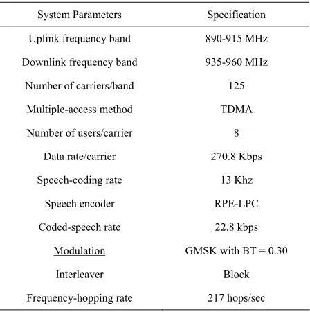
The Table 3 bellow show the characteristics of GSM. The peak data rates achieved by GSM are 13 kb/s for full rate speech encoded voice signal TCH/FS. Figure 5 shows how the modulation data are generated from the encoded speech data.
The speech data are generated by encoding the speech samples with duration of 20 msec into 260 bit blocks. The data rate corresponds to 13 kb/s.
The 260 bits data blocks are divided into two classes:
Table 3. Table of GSM specification.
System Parameters
Specification
Uplink frequency band
890-915 MHz
Downlink frequency band
935-960 MHz
Number of carriers/band
125
Multiple-access method
TDMA
Number of users/carrier 8
Data rate/carrier
270.8 Kbps
Speech-coding rate
13 Khz
Speech encoder
RPE-LPC
Coded-speech rate
22.8 kbps
Modulation GMSK with BT = 0.30
Interleaver
Block
Frequency-hopping rate
Figure 5. GSM modulation.
1)Class I: Includes 182 bits which are sensitive to bit errors and are considered as important. These bits are encoded using convolutional coding with the rate of ½ and a constrain length 4. The 182 bits are split into 50 bits (Class Ia) and 132 bits (Class Ib). Before convolu-tional encoding, 3 cyclic redundancy check bits (CRC) generated by the block encoder are added to the class Ia bits and 4 tail bits are added to the Class Ib bits.
2)Class II: Includes 78 bits which are less important and are transmitted without protection.
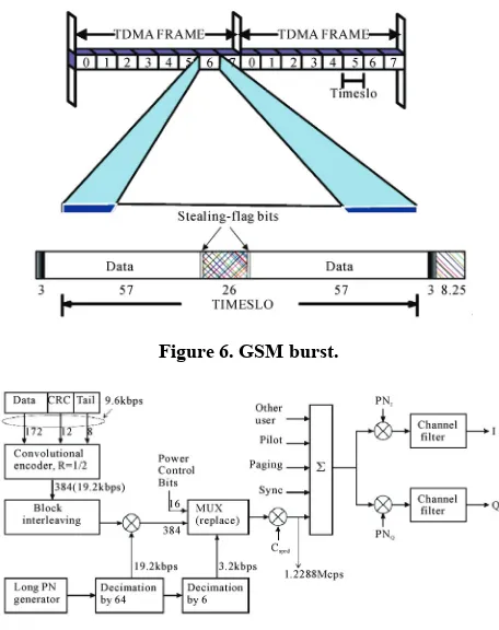
After channel coding the resulting 456 bits are inter-leaved and multiplexed with the slow associated control channel data (SACCH) and the dummy bits to build a multiframe with a time duration of 120 ms. The multi- frame includes 24 traffic channel frames, 1 idle frame and 1 slow associated control channel frame. After en-cryption, the different user frames are multiplexed to build a time frame with 8 time slots, each time slot in-cludes in case of the traffic channel 2 × 57 bits. In the last step, the time slots are formatted to build the data bursts as show in Figure 6.
3.2. CDMA IS-95a (CDMA One)
Code Division Multiple Access (CDMA) was originally developed by Qualcomm; it is also referred to as CDMAOne and its standard designation IS-95A. This technology uses individual code designations to distin-guish carrier channels in the spectrum from one another, in place of the frequency or time division systems in use by the technologies such as GSM. However, CDMA is similar to FDD systems such as GSM in that it uses one radio channel for sending information from base stations to end-user devices (downlink), and a separate channel for the uplink.
CDMA uses a 1.25 MHz radio channel and support data rates of up to 14.4 kbps. Its architecture is based on a packetised backbone and its transport protocol is very similar to the computer transport network. Under this protocol, data information is split into packets. Each packet contains information data code and an overhead for error control, addressing and reassembly information
that enable the network to organize information at the receiving end. CDMA efficiency depends on the number of users that concurrently communicate with the base station as these users compete for finite power provided by the transmitter. This phenomenon, known as cell breathing, significantly reduces the range of the commu-nication network. In addition, CDMA does not benefit from the same roaming capabilities that have helped to make GSM the dominant mobile standard.
Figure 7 shows how the traffic signal is encoded and mapped into 20 ms frames before spreading, scrambling, and modulation.
After data coding and interleaving, the signal is en-crypted with the long PN code. From each frame con-taining 384 encoded data bits, 16 are replaced by power control bits. The location of the power control bits is fixed by 4 bits derived from the PN code which is deci-mated by 6 to four times 800 kbps. The power control bit rate is also 800 kbps and for each power control bit, 16 locations are possible. After Spreading and adding the other user and logical channel, the I and Q signals are generated by using two different real scrambling codes.
[image:4.595.310.538.421.709.2]The data rate can be reduced after each frame from 9.6 kbps to 4.8 kbps, 2.4 kbps or 1.2 kbps (rate set 1) by us-ing symbol repetition after convolutional encodus-ing. The mobile terminal must always support the rate set 1, but may also support a second rate set (rate set 2), which is derived from the data rate 14.4 kbps and include the rates
Figure 6. GSM burst.
7.2 kbps, 3.6 kbps and 1.8 kbps. In the rate set 2, 2 of 6 bits have to be punctured before block interleaving.
4. 2.5 G Networks
“Generation 2.5” is a designation that broadly includes all advanced upgrades for the 2G networks.
Generally, a 2.5G GSM system includes at least one of the following technologies:
1) High-speed circuit-switched data (HSCSD) 2) General Packet Radio Services (GPRS) 3) Enhanced Data Rates for Global Evolution (EDGE).
An IS-136 system becomes 2.5G with the introduction of GPRS and EDGE, and an IS-95 system is called 2.5G when it implements IS-95B, or CDMA2000 1xRTT up-grades
4.1. HSCSD
HSCSD uses a maximum of four circuit-switched time-slots (each timeslot has throughput of 9.6 kbps on 900 MHz networks, or 14.4 kbps on 1800 MHz networks) to increase data rates to a maximum of 38.4-57.6 kbps, pro-vided that the timeslots are high speed data (HSD) capa-ble. This technology requires a software upgrade for the GSM network infrastructure base.
4.2. GPRS
GPRS is a more radical step in the development of GSM towards higher data rate communication and was intro-duced into GSM networks as an intermediate step be-tween 2G and 3G. The implementation of GPRS allows a move away from circuit-switched data to the delivery of packet data based on GSM’s TDMA technology. The packet switching nature of GPRS makes mobile data faster and cheaper and offers continuous connectivity and access to online services. Some operators have cho-sen to charge users as a function of data transmitted rather than connection time, as is the case for GSM voice calls, because GPRS uses network resources and band-width only when data is actually transmitted.
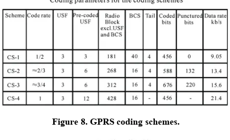
GPRS capability to provide a higher data rate relies on the different coding schemes defined in its specifications. There are four different coding schemes (Figure 8), each with a different level of error correction overhead. The level of overhead is inversely proportional to the avail-able throughput; that is, the lower the channel protection, the higher and the throughput available. The maximum theoretical throughput – 171.2 kbps – corresponds to the coding scheme 4 (CS-4)
4.3. EDGE
The main difference between GSM and EDGE consists
on the data modulation which is based on 8-PSK instead of GMSK modulation used by GSM. In this way the data rate provided by EDGE is 3 times higher than GSM (up to 384 kbit/s).
In each EDGE burst as shown in Figure 9, 346 coded data bits can be transmitted. Due to the lower symbol distance comparing to GSM, EDGE requires a better transmission quality. This can be achieved by reducing the cell size trough increasing the number of the base stations
4.4. CDMA2000 1 × RTT (1X)
The next phase of cdmaOne development was the Single Carrier Radio Transmission Technology (1 × RTT) CDMA standard (increasingly known as just ‘1X’), an enhanced capability technology that provides increased capacity and data rates up to 144kbps for mobile devices.
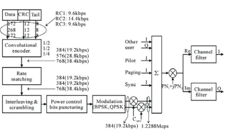
The main difference to IS-95 is the use of complex scrambling and depending on the radio configuration; the data can be modulated using QPSK instead of BPSK before spreading. In case of downlink, 9 different radio configurations (RC1-RC9) are defined in cdma2000 standard. The five first radio configurations (RC1-RC5) are based on the spreading rate 1 and provide a maxi-mum data rate of 307.2 kbps (RC4) while the four last radio configurations (RC6-RC9) are based on the sprea- ding rate 3 used in the multi-carrier technique. Figure 10 shows for the three different radio configurations (RC1, RC2 and RC3) the performed data processing steps be-tween the user data and the IQ modulated signal.
5. 3G Networks
[image:5.595.310.535.520.657.2]The principal objectives of 3G networks are the delivery of higher data rate services with worldwide compatibility.
Figure 8. GPRS coding schemes.
Figure 10. 1 × RTT modulation.
The promise of new radio spectrum encouraged some of the world’s mobile operators to pay very high prices for 3G licenses. Most 3G systems will operate in the less crowded IMT-2000 core band, operating at 2 GHz. This band has been largely dedicated to 3G services, promis-ing licensees sufficient capacity for the network expan-sion necessary to host new value-added data services.
The main 3G networks currently deployed are based on WCDMA and EV-DO. A summary of some of the key features of the two systems is shown in Figure 11.
Third Generation Partnership project (3GPP) The Third Generation Partnership project (3GPP) de-fines a range of standards including WCDMA, TD- CDMA and refinements to GSM, GPRS and EDGE. 3GPP is a cooperation of ETSI (Europe), ATIS (North America), CCSA (China), TTA (South Korea) and ARIB/TTC (Japan) to create a global 3G standard that follows the ITU’s IMT-2000 project.
3GPP technologies are based on the GSM evolution path and the identified 3G standard is now widely known as Universal Mobile Telecommunications Sys-tem (UMTS). UMTS is the European/Japanese answer for 3G system standardisation and is sometimes referred to as 3GSM, depicting the evolution of the GSM tech-nologies towards a 3G standard.
3GPP standards include several hundred specifications and are categorized in Releases; Figure 12 lists the 3GPP standards defining the operation of 3G and beyond.
3GPP is generally seen as the most important stan-dardisation body in the mobile segment and has defined many important systems, including WCDMA, HSDPA, HSUPA, TD-CDMA, TD-SCDMA and IMS. 3GPP is also in the process of defining Long Term Evolution (LTE), a standard that will attempt to specify systems that this report classifies as 3.9G.
3GPP2
3GPP2 was established in December 1998 and is col-laboration between ARIB and TTC in Japan, CCSA in China, TIA in North America and TTA in South Korea. As with 3GPP, the aim of this standardisation group is to oversee the development of a global 3G standard. How
Figure 11. 3G networks features.
Figure 12. 3GPP releases.
ever, in practical terms, 3GPP2 is responsible for the standardisation of CDMA2000, a 3G technology based on CDMA standards which is primarily used in North America, South Korea and Japan.
5.1. Wideband Code-Division Multiple Access (WCDMA)
WCDMA is a 3GPP and IMT-2000 standard derived from CDMA. It is a third-generation wireless network technology offering much higher data speeds to portable devices than most 2.5G networks.
WCDMA can support images, data and video commu-nication at 384 Kbps with full mobility, with a theoreti-cal maximum of 2 Mbps for fixed and nomadic usage. WCDMA systems operate in a wide 5 MHz channel, compared with the 200 KHz carrier for GSM/GPRS, which is a basic reason why WCDMA delivers faster data rates and increased capacity when compared with previous networks.
WCDMA operators typically have allocations of be-tween 20-40MHz (2 × 10 MHz up to 2 × 20 MHz) of spectrum in the paired FDD bands of 1920-1980MHz (which is used for uplink) and 2110-2170MHz (downlink) as shown in Figure 13.
5.2. CDMA2000 1 × EV-DO Release 0
[image:6.595.313.533.660.699.2]CDMA2000 1 × EV-DO Release 0 (EV-DO) was the first attempt to bring higher data rates to existing CDMA2000 1 × RTT networks. It allows data rates of up to 2.4 Mbps in the downlink, but commercial implementations have
limited this to around 300-600 Kbps since several users have to be catered for Cdma2000 1 × EV-DO (Single Carrier Evolution-Data Optimized) is specified for the frequency bands which are only reserved for the data transmission. By using turbo coding in addition with 16-QAM and 8-PSK as modulation format, a maximum data rate of 2.4576 Mbps and 1843.2 Mbps can be achieved for downlink and uplink, respectively. The frame structure has been also changed in this sub- standards, the pilot and the control channels are no more transmitted in parallel using different spreading codes, they are time multiplexed with the traffic channel. From the time frame, with 1280/3 ms duration, 40/3 ms have been reserved for the control channel and the rest is used for the traffic channel.
The frame part reserved for the traffic channel is di-vided into 248 time slots which can be assigned to dif-ferent users with variable data rates for time domain multiple accesses. Each time slot with the time duration of 1.667 ms include 4 × 400 data and preamble chips, 4 x 64 MAC chips and 2 × 96 pilot chips. Figure 14 shows the forward channel structure including traffic channel coding, spreading, modulation, and time multiplexing of traffic, pilot, medium access control channel, and pream-ble bits.
6. 3.5G Networks
[image:7.595.59.289.471.707.2]The main objective of the 3.5G is to increase the throughput to about to 20 Mbits/s, but in practice the data speed is about 1Mbps. The Figure 15 bellows summa-rize the most 3.5G with some characters.
Figure 14. 1 × EV-DO coding.
Generation Network Launch Frequencies (MHz) Peak data rates Average data Main Main Service
TD-CDMA (UMTS TDD) 2003
450-480; 850-900; 1900-1920; 2010-2025;2053-2082; 2500-2690;3400-3600
5Mbps 1Mbps Data + VoIP
HSDPA 2005 800, 850, 1900, 2100 14.4Mbps* 0.55-1.1Mbps Voice + data
HSUPA 2007 800, 850, 1900, 2100 14.4Mbps*; 5.7Mbps** TBD Voice + data
CDMA 1xEV-DO Rev A 2007 450; 800; 1700; 1900 3.1Mbps*; 1.8Mbps** TBD VoIP + data
CDMA 1xEV-DO Rev B 2008 450; 800; 1700; 1900 73.5Mbps*; 27Mbps** (in 20MHz channel)
TBD VoIP + data 3.5G
Figure 15. 3.5G networks.
6.1. High Speed Downlink Packet Access (HSDPA)
High Speed Downlink Packet Access (HSDPA) is a 3.5 G upgrade for existing WCDMA networks. Its key ad-vantages are that it improves maximum downlink data rates to 14.4 Mbps, compared with 2 Mbps for WCDMA, reduces latency to 100ms, compared with 180-200 ms for WCDMA, and can improve base station data capacity by a factor of five in dense urban environments HSDPA introduces a new transport channel – formally known as high-speed downlink shared channel (HS-DSC) – that uses a number of intelligent and adaptive techniques to improve performance.
Some of HSDPA’s other key features include: 1) Adaptive Modulation and Coding (AMC)
By sending acknowledge reports from the CRC check to the base station, the base station can retransmit the data frame in case of incorrect transmission using a dif-ferent puncture scheme (soft combining and incremental redundancy)
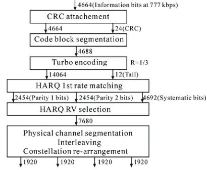
2) Hybrid Automatic Repeat Request (H-ARQ). By using shorter radio frames with time duration of 2 ms equivalent to 3 W-CDMA time slots and by moving the medium access control (MAC) to the node-B (BTS) rather than in the radio network controller (RNC), the coding and the modulation schemes can be adapted rap-idly to the quality of the radio link using the fast sched-uling function. In case of good transmission condition, 16-QAM can be used instead of QPSK. For the encoding, turbo-encoding with a fixed rate of 1/3 is used and the coding adaptation is based on different rate-matching which affects the effective code rate. Figure 16 shows how the information data coding is performed.
6.2. High Speed Uplink Packet Access (HSUPA)
[image:7.595.322.527.535.703.2]Though HSDPA includes higher data rates for downloading,
the upload data rates are still limited by the 3G system. As an evolutionary upgrade to HSDPA, High Speed Up-link Packet Access (HSUPA) brings a faster upload channel (up to 5.76 Mbps) in order to provide a more symmetric communication channel and allow full-duplex packet services to be used. HSUPA, which is also re-ferred to as uplink enhanced dedicated channel (E-DCH), uses some of the same techniques as HSDPA but applies them to the uplink rather than downlink.
HSUPA was released as a part of 3GPP Release 6 during March 2005 and is now in the process of being demonstrated by infrastructure vendors around the world. Unlike HSDPA, HSUPA uses lower order modulation schemes in order to conserve battery life at the user ter-minal. Another reason for not including more advanced modulation schemes is that these may impose higher amplifier requirements at the terminal – which would mean bigger size and possibly more heat dissipation.
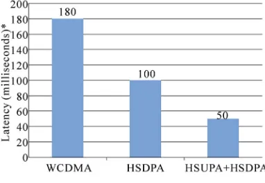
The Figure 17 shows that HSDPA reduces latency in the downlink, HSUPA reduces latency in the uplink, making the overall latency of the system (both downlink and uplink) acceptable for real-time applications includ-ing VoIP. VoIP services generally require a round-trip latency of 100ms or less to provide acceptable quality, and networks with both HSUPA and HSDPA have RTT latency of around 50 ms.
6.3. CDMA2000 1 × EV-DO Revision A
CDMA2000 1xEV-DO Revision A (EV-DOrA) is the 3 GPP2’s version of 3.5G. Building on the success of EV-DO Release 0, EV-DOrA brings higher data rates to both downlink and uplink and includes some significant improvements. EV-DOrA supports downlink data rates of up to 3 Mbps and uplink rates of up to 1.8 Mbps, al-lowing for full duplex services to be used, including video communications and other multimedia-rich ser-vices.
[image:8.595.74.265.578.710.2]Apart from the increase in data rates, the most impor-tant aspect of EV-DOrA is that an all-IP air interface is introduced. Consequently, VoIP services can be used over the mobile network accompanied by competitive
Figure 17. Delay comparison.
data and multimedia services. Moreover, EV-DOrA al-lows QoS for low latency applications, multicast capa-bilities and higher system capacity..
6.4. CDMA2000 1xEV-DO Revision B
CDMA2000 1 × EV-DO Revision B (EV-DOrB) intro-duces even higher data rates for the communication link by aggregating frequency carriers to increase capacity. Overall, it is expected that there will be up to 15 carriers of 1.25 MHz each within 20 MHz of bandwidth.
EV-DOrB includes intelligent algorithms in the Me-dium Access Control (MAC) layer to optimise the com-munication link, much like HSDPA or any new commu-nication network.
EV-DOrB also introduces new modulation schemes, the most significant of which is 64-QAM. This allows considerably higher data rates assuming that the channel enjoys very favorable conditions. In the case when a user is stationary or in the vicinity of the base station, higher data rates will be available, but as the user becomes mo-bile or is near the edge of the cell, 64-QAM will not be able to provide service and another – more robust – modulation scheme will have to be used
6.5. Time Division CDMA (TD-CDMA)
Contrary to WCDMA, which uses frequency duplex (different frequencies are used for the uplink and downlink), TD-CDMA multiplexes both channels into different timeslots.
Therefore, it uses a single frequency channel and al-lows the operator to allocate bandwidth to the downlink or uplink. Although this may not be necessary in voice communications that require symmetric links, data communications usually require asymmetric links, with the downlink requiring much higher bandwidth than the uplink.
TD-CDMA is promoted by the UMTS TDD Alliance, which aims to provide a forum for development issues as well as to promote the UMTS TDD market environment. TD-CDMA provides several advantages compared with WCDMA. Higher data rates are available since resource allocation extends to the time domain and latency is also inherently improved. Initial implementations of TD- CDMA systems have illustrated data rates of up to 5 Mbps and latency as low as 50 ms, but practical applica-tions are expected to be limited to 1 Mbps.
7. 3.9G Networks
a broad consensus within the industry on terminology, with some preferring to use other terms such as 3.99G, Super 3G or Beyond 3G. In this report Informa Telecoms & Media uses the terms 3.9G or LTE to refer to this group of emerging technologies and standards.
[image:9.595.308.538.79.157.2]3.9G technologies aim to improve the performance of 3.5G networks significantly and to provide some back-ward-compatibility with those networks. In particular, 3.9G networks are being designed to use 3G spectrum allocations, as opposed to 4G systems, which will require new spectrum.
Figure 18. 4G requirements.
elements of mobile, wireless and fixed networks in a seamless architecture transparent to the user.
2) Target data rates should be 100Mbps for mobile us-ers and 1Gbps for nomadic usus-ers.
8. WIMAX Evolution
3) Worldwide common spectrum and open global standards should be pursued.
WiMAX, which stands for Worldwide Interoperability for Microwave Access, is a global effort to evolving fixed-wireless technology to support mobility, which will bring WiMAX into competition with 3G/3.5G technolo-gies such as WCDMA/HSDPA and EV-DO/EV-
10. Conclusions
The architecture of 4G systems is also likely to be design to deliver the long-held industry vision of seamless ac-cess to services across multiple mobile, wireless and fixed networks. This could be enabled by a range of technologies including IMS, IPv6, OFDMA, MIMO.etc. The 4G networks should also be planned and optimized to support these different services (mobiles and fixes) with differents QoS.
DOrA.
The 802.16 standard family is defined by the IEEE. The vision has changed a lot in the last 10 years:
1) 1998: IEEE formed 802.16 group to develop a stan-dard for a wireless metropolitan area network (MAN) as fixed wireless access
2) 2004: Standards ratified 802.16 and two bands has been defined 10-66GHz for LOS, and 2-11Ghz for NLOS.
11. References
3) 2005: The standard 802.16e is completed to allow mobility application in the band 2-6GHz
[1] M. Roberts and S. Sherrington, Future Mobile Broadband, 2007.
4) 2006: The product is certified with WIMAX as commercial name.
[2] CDMA Developer Group, 23 July 2007. http://www.cdg.org
WIMAX is started as fixed broadband now it is really
the first 3.9G network. [3] “Cingular Wireless: Spectrum Efficiency Comparison, GSM vs. UMTS vs. 1 × RTT,” Research Material, 14 March 2002.
9. 4G Networks
[4] “Mobile Applications & Operating Systems,” 3rd Edition, 17 October 2006.
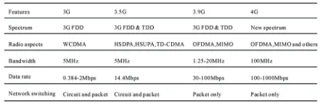
Fourth-generation (4G) networks are still at an early stage of development – so early in fact that there is no industry consensus on the definition of 4G. However, the ITU has developed a recommendation for an initial working definition of ‘Advanced Technology Evolution’, its term for 4G (Figure 18) which can be summarised as follows:
[5] “World Cellular Information Service,” August 2007. [6] “Radio Transmission and Reception,” Technical
Specifi-cation Group GSM/EDGE Radio Access Network, 3rd Generation Partnership Project, 2005.
[7] “User Equipment Radio Transmission and Reception (FDD),” Technical Specification Group Radio Access Network, 3rd Generation Partnership Project, 2005.