Dynamic Strain Aging Behavior of Alloy 600
in a High Temperature Coolant Environment
Jiunn-Yuan Huang
1,+, Yu-Ting Huang
2, Chien-Pu Tu
2, Ge-Ping Yu
2,
Jia-Hong Huang
2, Wen-Feng Lu
1,3and Kun-Chao Tsai
11Institute of Nuclear Energy Research, 1000 Wenhua Road, Longtan, Taoyuan 32546, Taiwan 2Department of Engineering and System Science, National Tsing Hua University, Taiwan
3Department of Materials Science and Engineering, National Taiwan University, Taiwan
The slow strain rate tests were conducted on cold-worked Alloy 600 at a nominal strain rate 1©10¹6s¹1in air and in a simulated BWR
coolant environment. The dynamic strain aging phenomenon at 200°C, 250°C, 275°C and 300°C was studied. The jerkyflows of small and large
serration amplitude observed on the stress-strain curves were respectively categorized as type B and D serrations. The serratedflow is more
significant for those specimens with lower cold work levels tested at higher temperatures than those with higher cold work levels tested at lower
temperatures. For the cold-rolled SSRT specimens tested in the 200°C water environment, the largest reduction of area along with the smallest elongation was observed. It could be accounted for by the localized deformation induced by dynamic strain aging. The strain hardening exponent generally increases with increasing the test temperature and decreases with an increase of the cold work level.
[doi:10.2320/matertrans.M2015160]
(Received April 20, 2015; Accepted September 14, 2015; Published November 25, 2015)
Keywords: slow strain rate tests, dynamic strain aging, jerkyflow, localized deformation
1. Introduction
Inconel 600, a substitutional nickel-base alloy, has been widely used for the components of boiling water reactors (BWRs) and pressurized water reactors (PWRs) in high temperature and high pressure water environments thanks to its excellent mechanical properties and high temperature corrosion resistance. However, after decades of operation, SCC incidences have been observed with the steam generator tubes and reactor pressure vessel head penetrations made of Alloy 600. In recent years, studies on dynamic strain aging (DSA) phenomena have been mainly focused on the austenitic stainless steels, particularly on SS 316L stainless steel,13) some on nickel-base alloys.48) The DSA model,9) solute dragging model, was first proposed by Cottrell. The solute atoms diffuse to the perimeter of the mobile dislocations and form solute atmospheres to drag down the moving dislocations when the velocity of dislocations approximately equals to that of solute atoms in the stress
field of dislocations. The dragged dislocations require larger force to break themselves away from the solute atmospheres. The repetitions of dragging down and breaking away of the dislocations induce the serrated flow on the stressstrain curve. There are other manifestations, such as work harden-ing, negative strain rate sensitivity, lower elongation and localized deformation, for occurrence of DSA in the appropriate region of temperature and strain rate.1012) The occurrence of DSA depends on material chemical composi-tion, grain size, test temperature, strain rate, and prior deformation. No work on the DSA of Ni-base alloy tested in water has been reported. It is of academic and technical interest to study the dynamic strain aging phenomenon of Alloy 600 in an oxygenated water environment. This work was to study the DSA behavior of the cold-rolled Alloy 600 in an oxygenated water environment at elevated temperatures
ranging from 200°C to 300°C. Alloy 600 cold worked to three different levels was employed to investigate the effect of dislocation density on the phenomena of DSA, and the effect of DSA on the deformation behavior of Alloy 600 in an oxygenated water environment. These results may help better understand the degradation mechanism of the reactor components in BWR coolant environments.
2. Experimental Procedures
2.1 Sample preparation
Forged Alloy 600 manufactured by Bodycote plc was tested for a study of the DSA behavior of Alloy 600. Their chemical compositions and mechanical properties are given in Tables 1 and 2, respectively. Three cold work levels, 10%, 20% and 30%, were obtained by multi-pass cold rolling along the uni-axial direction.
2.2 Microstructure analysis
In order to reveal microstructure, optical metallographic (OM) examinations were carried out on the as-received and cold-worked specimens. The metallographic specimens were sampled from the middle of the cold-worked specimens and prepared following the standard metallographic preparation procedures. The polished specimens were electrolytically etched by using 70% phosphoric acid (H3PO4) at 6.0 V for about 10 s at room temperature. For carbide precipitate examinations, the polished specimen was etched by 5% oxalic acid at 6.0 V for about 3 s at room temperature. The carbide precipitates were further examined by a scanning electron microscope (SEM) and an electron probe micro-analyzer (EPMA), to identify the carbide composition and distribution.
2.3 Hardness measurement for the cold-worked speci-mens
The Vickers microhardness measurements were conducted
+Corresponding author, E-mail: jyhuang@iner.gov.tw
across the thickness of the cold-worked specimens at a dead weight of 1 kg on the etched metallographic specimens. A comparison was made between the carbide band and non-carbide band regions of the cold-worked specimens.
2.4 Slow strain rate tensile (SSRT) test
The configurations and dimensions of the slow strain rate specimens tested in water are shown in Fig. 1. The slow strain rate tests were conducted in a closed-loop, servo-electric machine with an integrated water circulation loop to simulate a BWR water environment under displacement control at a nominal strain rate 1©10¹6s¹1. The load was measured by using a load cell inside the autoclave, which measured the applied load exclusive of the friction force between the pulling rod and the sealing material. The oxygen level in the water environment was maintained in a range of 6 to 8 wppm. The conditions of the water environment are summarized in Table 3. Prior to testing, the specimens were pre-oxidized for one week in water containing 6³8 wppm of oxygen at the test temperature.
3. Results and Discussion
3.1 Microstructure analysis
The grain sizes of the as-received Alloy 600 specimens are not uniform. The higher the cold work level, the smaller the
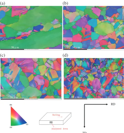
grain size of the Alloy 600 specimen was obtained, as shown in Fig. 2. L, T, and S stand for the plane with its normal perpendicular or parallel to the rolling direction respectively, as specified in Fig. 2. The grain size distributions of the Alloy 600 specimens subjected to different cold work levels are summarized in Fig. 3. The maximum and minimum grain sizes in each plane (L, T, and S) are also specified. The 30% cold-worked Alloy 600 shows the smallest grain size and also the slightest variation. These results have been further confirmed by the EBSD examination and shown in Fig. 4. The crystal orientation distribution map identifies the grains in different orientations with different colors. The matrix phase is the Ni £ phase, fcc phase. The constituent carbide Unit: mm
t1
(15mm)
Specimen
Fig. 1 Configurations and dimensions of the SSRT specimen tested in the
[image:2.595.50.545.85.114.2]water environment.
Table 3 The water chemistry conditions of the oxygenated water loop.
Test parameters Oxygenated water
Pressure, MPa 10
Temperature, °C 200, 250, 275, 300
Conductivity (inlet), µScm¹1 0.07
Conductivity (outlet), µScm¹1 0.13
Oxygen (inlet), ppm 7.1
Oxygen (outlet), ppm 6.7
pH (inlet) 5.95
pH (outlet) 6.17
Autoclave exchange rate, time/hour 1
(a) (b)
(c) (d)
Rolling direction L
S
T
Fig. 2 SEM metallographic features of Alloy 600: (a) as-received Alloy
[image:2.595.48.549.151.206.2]600, (b) 10%cold-rolled; (c) 20%cold-rolled; (d) 30%cold-rolled.
Table 1 Chemical compositions of Nickel-base alloy 600 (mass%).
Content Ni Cr Fe C Si Mn Co S Cu Al Ti Nb
[image:2.595.63.279.244.425.2]Alloy 600 70.87 14.86 5.974 0.036 0.403 0.50 0.02 0.001 0.004 0.085 0.003 0.001
Table 2 Mechanical properties of Nickel-base alloy 600.
Specifications Test temperature
UTS* (MPa)
YS** (MPa)
TE*** (%)
UE**** (%)
Alloy 600 25°C 671 333 28.7 24.7
300°C 613 321 26.0 20.6
[image:2.595.305.549.257.376.2] [image:2.595.306.547.280.581.2]phases, Cr23C6 and Cr7C3, could hardly be identified by EBSD, whose phase ratios are lower than 1%. However, the carbides in the 20% cold-worked specimen could be clearly distinguished by EPMA color mapping analysis, shown in Fig. 5. The precipitates are mainly composed of Cr23C6. The question is if the recrystallization of Alloy 600 could occur at temperatures as low as observed with this work, around 50°C. A hypothesis is proposed to account for the observation of the smaller grain sizes with the specimens of higher cold work levels. Alloy 600 with high stacking fault energy12)would facilitate the cross slip of dislocations when deformed. A synergy of cross slip and plastic deformation induced during the cold work process would prompt dynamic recrystallization13)to occur in Alloy 600 specimens at a lower
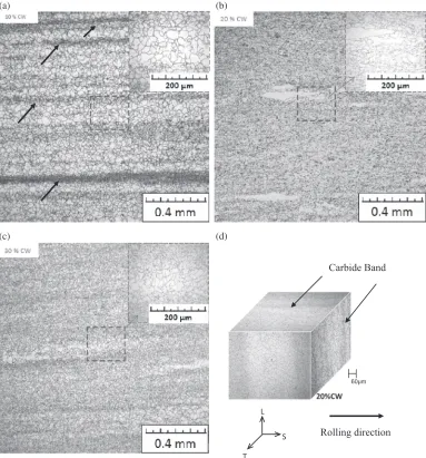
temperature. While specimens are cold worked, dislocations are generated with plastic deformation and the induced strain energy is concurrently expended to enhance cross slip of dislocations. The dynamic recrystallization occurred during the rolling process, which is different from the static recrystallization caused by heat treatment. The carbide precipitate bands in the cold-worked specimens were observed to be parallel to the cold roll direction, as exemplified in Fig. 6. For the 10% CW specimen, the carbide bands could be clearly observed along thefine grains. For the 20% and 30% CW specimens, the carbide bands became diffuse and the precipitates evenly distributed in the base metal. The areal fraction of carbide band for the 10% CW specimen calculated from the image analysis results is about 23.3%, which is the ratio of the carbide band area, i.e. small grain area, to the total observation area. Those for the 20%and 30%CW specimens are in the same range with an average of 85.7%. But the grain size for 30%CW is smaller than that for 20%CW. The smaller the grain size, the greater number of carbide precipitates was observed, because most of the carbides precipitated along grain boundaries. The precipitation of carbides could be assisted by plastic deformation.1416) There was no carbide band observed for the as-received Alloy 600.
3.2 Hardness measurement for cold-worked Alloy 600
The Vickers microhardness distribution across the short transverse of Alloy 600 is shown in Fig. 7. The hardness measurements for the carbide band region, i.e. small grain size region, are higher than those for the non-carbide band region, as illustrated in Fig. 7 and Table 4. The higher the cold work level, the more uniform hardness was observed. The 10%cold-worked specimen shows the largest hardness difference between the carbide and non-carbide region.
3.3 Slow strain rate tensile (SSRT) test
Figure 8 shows the typical stress-strain curves for the Alloy 600 cold worked to different levels tested at 300°C in water and in air. Jerky flow was clearly observed on all the stress-strain curves. The data points from yield point to
Fig. 3 The grain size distributions of cold-worked Alloy 600 in different
orientations.
(a) (b)
(c) (d)
=50 μm; Map5; Step=0.1272 μm; Grid1024x704 =50 μm; Map5; Step=0.1272 μm; Grid1024x704 50ȫm 50ȫm
=50 μm; Map5; Step=0.1272 μm; Grid1024x704
50ȫm 50ȫm =50 μm; Map4; Step=0.126 μm; Grid1033x710
Fig. 4 Crystal orientation distribution maps showing grain evolution
examined by EBSD analysis for Alloy 600 under different cold work
levels, (a) as received, (b) 10%, (c) 20%, (d) 30%.
Fig. 5 Color mapping of carbide band in the 20%CW specimen on T-L
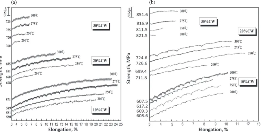
[image:3.595.64.273.65.249.2] [image:3.595.307.549.68.254.2] [image:3.595.50.288.296.551.2]ultimate tensile strength (UTS) can be fitted by the equation ·=K¾n, where · is the true stress, ¾ the true strain, n the strain hardening exponent, K the strength coefficient. The strain hardening exponents for cold-worked Alloy 600 specimens tested in water and air are plotted against test temperatures in Fig. 9. The strain hardening exponent can be recognized as the ability for materials to resist further deformation.17) The magnitude of the strain hardening coefficient reflects the ability of the material to resist further deformation. N=1 represents ideally elastic;n=0 ideally plastic materials. At the same cold work level, the exponent for the specimen tested in water is higher than that obtained in air. The strain hardening exponent generally increases with increasing the test temperature and decreases with increasing the cold work level of Alloy 600. At higher test temperatures, solute atoms with higher mobility have stronger interaction with dislocations to induce dynamic strain aging, so the ability for materials to resist further deformation is higher than that at lower test temperatures. The effect of temperature on the strain hardening exponent has been reported.18) The lightly cold-worked Alloy 600 leaves more room for
multiplication of dislocations during testing. So far, the authors don’t have good arguments to explain why the strain hardening exponent for the specimen tested in water is higher than that in air. More research is needed to study this issue. The elongation and reduction of area against the test temperature for the tests in water are shown in Fig. 10. It is interesting to note that the specimens tested in water at 200°C show the smallest elongation but the largest reduction of area. The stress-strain curves for the tests in 200°C water environment are given Fig. 11. It cannot reason out why the elongation tested at 200°C is small but with high reduction of area. That could possibly be accounted for by the localized deformation induced by DSA. The necking mainly occurred at the localized area, but contributed little to the total elongation. The jerky flow features of the stress-strain curves for the specimens tested in water and air are summarized in Fig. 12. There is no significant difference between the jerky flow features tested in water and air. The jerky flow features including small and large load drops on the stress-strain curve are further illustrated in Fig. 13. The small jerky flow is the so-called type B serration and the
(a) (b)
(c) (d)
Rolling direction
L
S
T
˩P
Carbide Band
Fig. 6 Carbide precipitate bands in the cold-worked specimens run parallel to the cold roll direction (carbide band was indicated by
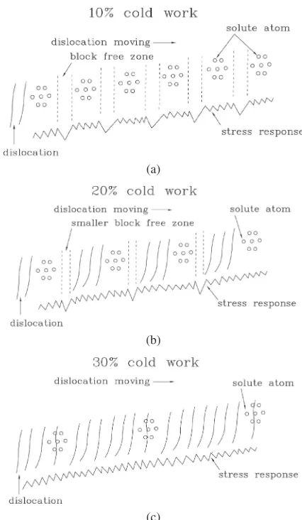
[image:4.595.107.490.71.482.2]large one type D serration.19,20)The type B jerkyflow offine serrations could be a result of the interaction of dislocations with clustered solute atoms. The large load drop in 10% cold-worked specimens occurs in a more frequent and periodical manner relative to the 20%and 30%cold-worked specimens tested in water and air environments. In particular, the 30% cold-worked specimens showed little or no large load drop in both water and air. These phenomena could be accounted for by a schematic illustration shown in Fig. 14. For the 10% cold-worked specimens with a low density of dislocation tangles, the solute atoms were evenly distributed in the matrix. During the SSRT tests, dislocations passed by the clustered solute atoms, which resulted in small amplitude stress response caused by the interaction between the solute atoms and dislocations. The large load drop was observed when dislocations kept moving away from the clustered solute atoms into a block free zone. The higher force would be needed when the dislocations came across the next clustered solute atoms. The 20%cold-worked specimens had a higher density of dislocations but less clustered solute atoms because plastic deformation induced carbide
precip-itation.1416,21,22) The higher the cold work levels, the more the dislocations were produced. The carbides preferably precipitated with assistance of strain energy around the dislocations. The carbide bands became prevalent in the heavily cold worked alloy, thus decreasing the number of solute atoms available for the interaction with dislocations in the matrix. When the multiplied dislocations induced by cold work went through the less clustered solute atoms, the large load drop became less frequent compared to those of 10% cold worked specimens. Furthermore, the 30%cold work had a highest density of dislocation tangles, which was due to dislocation multiplication induced by cold work. Therefore there was little or no block free zone present between the dislocation tangles. Under the circumstances, the multiplied moving dislocations interacting with the solute atoms showed only small load drops, no large load drop. In addition, the large load drop would become less frequent with an increase in elongation, till disappeared, as shown in Fig. 8. That implies the dislocations interaction effect becomes dominated when a specimen is deformed to a higher strain range. For those tested at 200°C, the amplitudes of jerky flow are smaller compared to those tested at higher temperatures. It could be reasoned that some of solute atoms lack thermal energy to diffuse to the moving dislocations at lower temperatures, the interaction between solute atoms and
Fig. 7 Hardness measurements along the thickness direction for the
[image:5.595.312.536.68.429.2]specimens subjected to different cold work levels.
Table 4 The hardness measurements for carbide band and non-carbide
band region of Alloy 600.
Specimen Average hardness (HV)
(non-carbide/carbide band region)
as-received 165.4
10%CW 229.3/249
20%CW 254.6/273
30%CW 271.2/284.6
(a)
(b)
Fig. 8 Typical stress-strain curves for the Alloy 600 of different cold work
[image:5.595.56.283.70.368.2] [image:5.595.46.291.439.514.2](a) (b)
In Water
In Air
Fig. 9 Strain hardening exponents for cold-worked Alloy 600 tested at different temperatures in (a) water and (b) air.
[image:6.595.73.527.73.255.2](a) (b)
Fig. 10 (a) Elongation and (b) reduction of area of cold-worked Alloy 600 against the test temperature in an oxygenated water
environment.
(a) (b)
[image:6.595.73.524.297.482.2] [image:6.595.75.526.541.772.2]dislocations becomes less active and the jerky flow consequently becomes less significant.
4. Conclusions
(1) The carbide precipitate bands in the cold-worked specimens were observed to be parallel to the cold roll direction. There was no carbide band observed with the as-received Alloy 600. The hardness of the carbide band region is higher than that measured in the non-carbide band region.
(2) A synergy of cross slip and plastic deformation would prompt dynamic recrystallization to occur in the cold-worked Alloy 600 specimens at a lower temperature. (3) For the cold-rolled SSRT specimens tested in the 200°C
water environment, the largest reduction of area along with the smallest elongation was observed. That could
be accounted for by the localized deformation induced by DSA.
(4) The serration of large load drop in 10% cold-worked specimens is in a more frequent and periodical manner relative to the 20%and 30%cold-worked specimens in water and air environments. That could be accounted for by the interaction between the dislocations and clustered solutes.
Acknowledgments
The authors would like to acknowledge the technical assistance from Mr. J. S. Huang and the financial support from the Institute of Nuclear Energy Research, Taiwan.
REFERENCES
1) V. Srinivasan, R. Sandhya, M. Valsan, K. Bhanu Sankara Rao and S.
Mannan:Int. J. Fatigue26(2004) 12951302.
2) W. Karlsen, M. Ivanchenko, U. Ehrnstén, Y. Yagodzinskyy and H.
Hänninen:J. Nucl. Mater.395(2009) 156161.
3) S. G. Hong and S. B. Lee:J. Nucl. Mater.340(2005) 307314.
4) K. Gopinath, A. Gogia, S. Kamat and U. Ramamurty:Acta Mater.57
(2009) 12431253.
5) H. Hänninen, M. Ivanchenko, Y. Yagodzinskyy, V. Nevdacha, U.
Type B : Small
jerky flow
Type D : Large
[image:7.595.319.532.66.432.2]jerky flow
Fig. 13 Illustration of jerkyflow features of the stress strain curve.
(a)
(b)
[image:7.595.63.279.67.281.2](c)
Fig. 14 Schematic illustration for the interaction between dislocations and
clustered solutes for Alloy 600 subjected to different levels of cold work,
[image:7.595.62.275.325.542.2](a) 10%, (b) 20%, and (c) 30%during SSRT test.
Fig. 12 Stress-strain curves for different cold worked Alloy 600 tested in
Ehrnstén and P. Aaltonen: Proc. 12th Int. Conf. on Environmental Degradation of Materials in Nuclear Power System-Water Reactor,
(2005) pp. 14231430.
6) C. Hale, W. Rollings and M. Weaver:Mater. Sci. Eng. A300(2001)
153164.
7) I. S. Kim and M. Chaturvedi:Trans. Japan Inst. Metals28(1987) 205
212.
8) R. Mulford and U. Kocks:Acta Metall.27(1979) 11251134.
9) A. H. Cottrell:Philos. Mag.44(1953) 829832.
10) P. Rodriguez:Bull. Mater. Sci.6(1984) 653663.
11) M. A. Meyers and K. K. Chawla:Mechanical Metallurgy: Principles
and Application, (Prentice-Hall, Inc., Eaglewood Cliffs, New Jersey, USA, 1984).
12) G. E. Dieter:Mechanical Metaggurgy, Third Edition, (McGraw-Hill
Book Company, 1986).
13) C. G. Panait, W. Bendick, A. Fuchsmann, A.-F. Gourgues-Lorenzon
and J. Besson:Int. J. Press. Vessels Piping87(2010) 326335.
14) K. B. S. Rao, M. G. Castelli, G. P. Allen and J. R. Ellis:Metall. Mater.
Trans. A28(1997) 347361.
15) J. Y. Huang, J. R. Hwang, R. C. Kuo and C. Y. Chen:Mater. Sci.
Technol.19(2003) 15751584.
16) J. Y. Huang, J. R. Hwang, J. J. Yeh, C. Y. Chen, R. C. Kuo and J. G.
Huang:J. Nucl. Mater.324(2004) 140151.
17) R. W. Hertzberg: Deformation and Fracture Mechanics of Engineering Materials, Second edition, (John Wiley & Sons, Inc., 1983).
18) S. Lou and D. O. Northwood:J. Mater. Eng. Performance3(1994)
344349.
19) P. Rodriguez:Bull. Mater. Sci.6(1984) 653663.
20) E. Pink and A. Grinberg:Mater. Sci. Eng.51(1981) 18.
21) A. Lamontagne, X. Kleber, V. Massardier and D. Mari: Application of Thermalelectric Power Technique to Study the Static Strain Ageing of Heavily Cold Drawn Steel, TMS, (Minerals, Metals and Materials, 2013).