In
fl
uence of Spinodal Decomposition on the Plastic Behavior
of Dynamic Electropulsing Treated ZA22 Alloy
Y. H. Zhu
1,+, S. To
1,+and X. M. Liu
21State Key Laboratory of Ultra-Precision Machining Technology, Department of Industrial and Systems Engineering,
Hong Kong Polytechnic University, P. R. China
2Hefei National Laboratory for Physical Science at Microscales, University of Science and Technology of China, Hefei, P. R. China
Dynamic electropulsing induced phase transformations and their effects on the plastic elongation of a furnace cooled ZnAl based alloy (ZA22) were studied by using backscattered scanning electron microscopy, transmission electron microscopy and electron back-scattered diffraction techniques. Under electropulsing, various transitional phases formed via the spinodal decomposition of ¡AFC phase. Adequate electropulsing provided favorable identities of both microstructure and dislocation due to pinning dislocation by transitional phases and second phase precipitates. The mechanism of effects of dynamic electropulsing on elongation of the alloy was discussed from the points of view of microstructural evolution and dislocation dynamics. [doi:10.2320/matertrans.M2012024]
(Received January 11, 2012; Accepted May 28, 2012; Published July 19, 2012)
Keywords: electropulsing, tensile deformation, spinodal decomposition, dislocation, zincaluminum alloy
1. Introduction
In our previous studies, it was reported that compared with that achieved by the normal ageing processes, electropulsing tremendously accelerated phase transformations by factors of at least 6000 and 3600 times in ZnAl based- and MgAl based alloys, respectively.1,2)The fundamental mechanism by
which such significant changes of phase transformations resulted from electropulsing, and their effects on the plastic behaviors of the alloys are not yet understood. It is of great practical importance and also of theoretical significance to study systematically the relationship between electropulsing induced phase transformations and the properties of the alloys.
There are two practical types of applying electropulsing: static electropulsing and dynamic electropulsing. The former combines a thermal process and electropulsing. The latter is a complex thermal process, which combines simultaneously both electropulsing and mechanical deformation. The effect of static electropulsing on elongation of a furnace cooled Zn Al abased alloy (ZA22) was previously studied.3)The present
work deals with dynamic electropulsing induced micro-structural changes and their effects on the plastic elongation of a previously furnace cooled ZnAl abased alloy (ZA22).
2. Experimental Procedures
Gross wire of eutectoid composition Zn22.1%Al2.6Cu (in mass%) was repeatedly cold-drawn to 1.5 mm in diameter. Before each cold drawing, the wire was tempered at 250°C for 20 min. Before electropulsing, the as-received wire was solution treated at 350°C for four days, then naturally cooled inside the furnace, i.e., furnace cooled (FC) to the ambient temperature. The FC alloy wire was cut into pieces of 100 mm length. The dynamic electropulsing treatment (EPT) was performed on the wire specimens being tensile
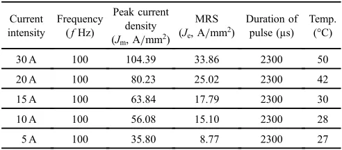
deformed. Multiple electropulses were applied on two electrical contactors with a distance of 80 mm. A self-made electropulsing generator was applied to discharge positive direction multiple pulses with various current intensities, 5, 10, 15, 20 and 30 A, through adjusting the controlling parameters. The frequency of the multiple electropulses was set at as 100 Hz, respectively. The pulse duration was kept to about 2300 µs. A jet oil cooling system was used to cool and protect the surface of the specimens. The surface temperature of the specimens was measured by a thermocouple for each test. Using an oscilloscope with a Hill effect component, various parameters of electropulsing, such as the peak density of current,jmand the mean-root-square of the current density, je, were determined. The results are listed in Table 1. The
[image:1.595.304.550.347.455.2]tensile tests were carried out at about ambient temperature with a crosshead speed, i.e., deformation rate, of 2 mm/min. The microstructural changes and phase transformation were examined using scanning electron microscopy in the back-scattered electron mode (BSEM). The BSEM based electron back-scattered diffraction technique (EBSD) is utilized to determine the local crystal structure and orientation of materials. The electron back-scattered Kikuchi diffraction patterns (EBKDP) are detected in SEM simply from bulk alloy specimens, rather than by using the transmission electron microscopy (TEM).4,5)The EBSD can also facilitate
Table 1 Operation parameters of the dynamic electropulsing of FC ZA22 alloy wires.
Current intensity
Frequency (fHz)
Peak current density (Jm, A/mm2)
MRS (Je, A/mm2)
Duration of pulse (µs)
Temp. (°C)
30 A 100 104.39 33.86 2300 50
20 A 100 80.23 25.02 2300 42
15 A 100 63.84 17.79 2300 30
10 A 100 56.08 15.10 2300 28
5 A 100 35.80 8.77 2300 27
+Corresponding author, E-mail: yaohuazhu@hotmail.com, mfsto@inet.
polyu.edu.hk
evidence of phase transformation by discriminating between phases having closely similar or even identical crystal structures. An EBSD examination was carried out on the Leo 1530 FESEM using a commercially available software from HKL Technology APS Ltd. (Oxford, UK). In perform-ing EBSD, the specimens were tilted at 70 degrees. The electron microscope scanned in step sizes of 0.3 µm.
3. Results and Discussion
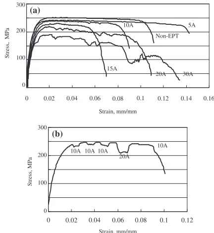
3.1 Tensile deformation
The tensile stress and the resulting strain of the furnace cooled ZA22 alloy specimens before and after dynamic EPTs with various current densities (5, 10, 15, 20 and 30 A) were measured. Stressstrain curves (SS curves) were plotted, as shown in Fig. 1. The elongation and the ultimate tensile stress of the non-EPT specimen were measured and found to be 11% and 251 MPa, respectively. The elongation of the 5 A-EPT specimen had increased to 14.2%, and reached a maximum with an ultimate tensile stress of 241 MPa. The elongation of the 5 A-EPT specimen had increased by 128%, compared with that of the non-EPT specimen. Upon further increasing the current intensity of electropulsing to 10 A, the elongation decreased to 9% with the ultimate tensile stress of 239 MPa. The elongation at the fracture of the 15-EPT specimen reduced to a critical value of 6.9%with the ultimate tensile stress of 235 MPa. Upon further increasing current intensity, the elongation at the fracture of the 20-EPT and 30 A-EPT specimens increased again to 11 and 13.4%, respectively. While the ultimate tensile stress kept reducing to 219 and to 189 MPa, respectively.
Prompt responses of instantaneous tensile stress against electropulsing were observed in the dynamic EPT specimen. Shown in Fig. 1(b) is a stressstrain curve of the repeatedly applied 10 A and 20 A EPT specimen. It can be seen that once
the electropulsing was applied to the specimen, the instanta-neous tensile stress decreased. When the electropulsing was removed, the instantaneous tensile stress increased promptly. By using this on/off EPT, the elongation of the repeatedly dynamic EPT specimen improved. This was due to the quick interaction between tensile induced dislocation and electropulsing.
3.2 Dynamic electropulsing induced phase transforma-tions
3.2.1 Spinodal decomposition and precipitation in ¡¤FC phase
Two ways of decomposition of the face centered cubic structure (FCC)¡AFCphase were observed in the 5 A-EPT FC
ZA22 alloy specimen under electropulsing: i.e., discontin-uous decomposition and contindiscontin-uous decomposition. The latter is the so called spinodal decomposition.
It is generally recognized that the spinodal decomposition occurs in a pattern: supersaturated phases¼GP zones¼ various transitional phases¼stable phases.69) The GP zones form at the early stage of decompositions of the phases, due to the fluctuation of composition of the supersaturated phases. After formation of the GP zones, the transitional phase appears in needle-shaped forms, which is followed by the transitional phases shaped in rods.
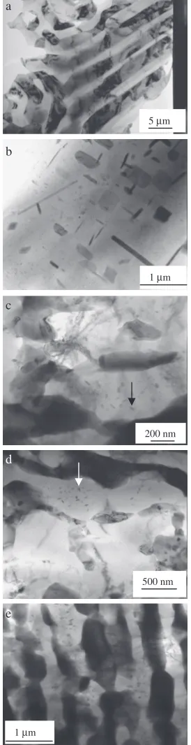
During furnace cooling, various metastable phases of¡AFC
formed in the FC ZA22 alloy. Accordingly, various transi-tional phases were observed in the FCC¡AFCphase in the 5
A-EPT specimen, as shown in Fig. 2(b). The first transitional phase (¡1
m) was in the shape of needles of about 0.43 µm in
length and about 0.02 µm in width. It was reported that the FCC ¡1
m phase formed along three preferential directions
of h110i, h011i and h101i with a lattice parameter of
a=4.404 A, and its orientation-relationship with the matrix
¡AFCphase wasð022Þ¡1m==ð022Þ¡0FC,½111¡1m ==½233¡0FC.8)
The second transitional phase in rod shape (¡2m) was about
0.37 µm in length and about 0.06 µm in width and the third transitional phases was of particles (¡3m) of about 0.44 µm in
length and about 0.50 µm in width, as shown in Figs. 2(b) and 3(a). The bright field, diffraction pattern and the dark
field image of ¡AFC phase, ¡2m and ¡3m in the 5 A-EPT
specimen are shown in Fig. 3. The diffraction pattern and the dark field image of the¡AFC phase are shown in Figs. 3(b1)
and 3(b2). The lattice parameter of the ¡AT phase was a=4.072 A. The ¡2
m phase had a hexagonal close packed
(HCP) structure witha=7.642 A,c=8.792 A,c/a=1.15, as shown in Figs. 3(c1) and 3(c2). The¡3
mparticles of about
0.44 µm in length and about 0.50 µm in width were detected as being of HCP structure with a=2.847 A, c=4.286 A,
c/a=1.51, as shown in Figs. 3(d1) and 3(d2). The final products of the spinodal decomposition of the ¡AFC phase
were FCC¡ATphase with a lattice parameter ofa=4.064 and
HCP ©AT phase with the lattice parameters of a=2.694 A, c=4.950 A andc/a=1.84.
In the 10 A-dynamic EPT specimen, the transitional phases disappeared. This implied that the spinodal decomposition of the¡AFCphase was completed after 10 A-dynamic EPT.
3.2.2 Discontinuous decomposition of ¡¤FCphase Accompanying the spinodal decomposition, discontinuous decomposition of the ¡AFC phase was observed as ¡AFC¼ 0 5A Non-EPT 10A 20A 15A 30A 200 100 0
Stress, MP
a
(a)
0
10A 10A 10A 20A 10A (b) Stress, MP a Strain, mm/mm 300 200 100 0 Strain, mm/mm 300 0.12 0.1 0.08 0.06 0.04 0.02 0.16 0.14 0.08 0.1 0.12 0.06
0.04 0.02
[image:2.595.59.275.504.739.2]©AT+¾AT+¡AT. The bright field images, diffraction patterns
and the dark field images of the hcp ©ATand ¾AT phases are
shown in Figs. 4 and 5, respectively. The lattice parameters of the ©AT and ¾AT phases are a=2.679 A, c=4.983, c/a=1.86 anda=2.679 A,c=4.628,c/a=1.72, respec-tively. The discontinuous precipitates of ©AT and ¾AT phases
remained in the 10 A-, 15 A-, 20 A-, 30 A EPT specimens.
3.2.3 Discontinuous decomposition of ©¤FCphase In the FC specimen, a discontinuous phase transformation,
©AFC¼©AT+¾AT+¡AT had occurred at the light imaged©AFC
boundaries. Dark imaged ¡AT precipitate in the shape of
particles were observed.9)BSEM images of the bulk part of
the tensile deformed non-EPT and dynamic EPT with various current intensities of electropulsing are shown in Fig. 6. The particle-shaped precipitates of¡ATdeveloped with increasing
elelctropulsing, as indicated by arrows in Figs. 6(b)6(f ). In the 15 A-dynamic EPT specimen, the¡ATparticle-precipitates
well grew. In the 20 A-dynamic EPT specimen, the quantity of the¡ATprecipitates increased and grew toward the inside of
the grains of©AFC. The¡ATprecipitates increased considerably
in the ©AFC phase, as shown in Fig. 6(f ). This implied
that the electropulsing induced discontinuous decomposition developed well at inside of the phase grains.
The discontinuous decomposition of the ©AFC phase was
also detected by using the EBSD examination. Lattice parameters of the five phases involved were determined using the TEM examination. These are listed in Table 2.5)
Using those previously determined lattice parameters of the phases, the EBSKDP were generated by scanning selected areas of 1.35©103 (µm) in the BSEM images of the bulk part of the tensile tested FC ZA22 alloy specimens. Fractional EBSD intensities of©AFCand©ATphases and their
ratios (©AFC/©AT) represent the changes of the relative amounts
of ©AFC and ©AT phases and the changes of the direction of
the discontinuous decomposition of the ©AFC phase. EBSD
mappings of©AFCand©ATphases are shown in Fig. 7. Listed
in Table 3 are the ratios of the fractional EBSD intensities of
©AFCand ©ATphases (©AFC/©AT) with various current intensities
of electropulsing. It can been seen that the ratios (©AFC/©AT)
decreased with increasing current intensity. This means that decomposition of ©AFC phase, ©AFC¼©AT+¾AT+¡AT,
accel-erated when the current intensity of electropulsing increased to 30 A. The EBSD examination confirmed the discontinuous decomposition of©AFC, which was detected using BSEM.
3.3 Spinodal decomposition enhanced internal stress
Figure 8 shows (0001) inverse polefigures of the©ATphase
of the bulk part, neck zone, rupture Part of the 5 A dynamic EPT and the 10 A dynamic EPT alloy specimens. From Fig. 8, it can be seen that in the stress concentrated rupture part of the tensile deformed alloy specimen, the EBSD project points of the ©AT phase had dispersed away from the
orientation of the (0001) planes. The changes of the stress
b
1 μm
d
500 nm
e
1 μm c
200 nm a
5 μm
[image:3.595.101.238.75.608.2]Fig. 2 TEM images of the bulk parts of the tensile deformed non-EPT (a) and dynamic EPT with various current intensities: 5 A (b), 10 A (c), 20 A (d) and 30 A (e) specimens.
Table 2 The lattice parameters for EBSD mapping deduced by TEM.4)
©AFC(hcp) ©AT(hcp) ¾AT(hcp) ¡AT(fcc) TA(bcc)
a0(A) 2.707 2.694 2.733 4.072 2.967
c0(A) 4.924 4.950 4.621
[image:3.595.304.550.84.142.2]c0/ao 1.818 1.837 1.690
Table 3 Ratios of fractional EBSD intensities of©ASand©ATphases (©AS/©AT) of the ZA22 alloy wires after Non-EPT and EPT with 5, 10, 15, 30 A.
EPT None 5 A 10 A 15 A 30 A
©AS/©AT 1.5 1.6 1.5 1.3 1.2 !
induced orientation of the ©AT phase was also previously
detected in the ZnAl based alloys.1012)
The EBSD project points of the©AT phase dispersed away
from (0002) in the 5 A EPT alloy specimen, as shown in Fig. 8(d). From the aforementioned TEM examination (Fig. 2), it was found that various transitional phases formed via the spinodal decomposition in the 5 A EPT specimen. This implied that plenty of transitional phases resulted in strengthening of the 5 A dynamic EPT specimen as compared with the 10 A dynamic EPT specimen. The transitional phases disappeared after 10 A EPT, as shown in Fig. 2(c). This meant that the spinodal decomposition was completed in the specimen. Accordingly, the project points of the ©AT
phase moved back toward (0002) planes, as shown in
Fig. 8(e). This implied that the stress in the specimen was reduced after 10 A dynamic EPT.
In general, electropulsing increase plastic elongation and decrease the strength of the alloy.1317) The fact that the transitional phases from the spinodal decomposition increased internal stress makes it possible to enhance plastic behavior, remained still a relatively higher strength of the alloy. The reason for that is discussed in the following part 3.4.
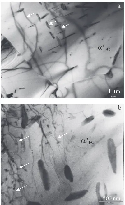
3.4 Dislocation pinned by transitional phases and second phases
From the aforementioned studies of dynamic electro-pulsing induced phase transformations, it was found that two kinds of precipitates formed in the dynamic EPT specimens.
a
b1 b2
c1 c2
d1 500 nm d2
1 μm 1 μm
1 μm
1 μm
1 μm 1 μm
Fig. 3 TEM brightfield image (a), diffraction pattern from B=[011] (b1) and the darkfield image ofð200Þreflection (b2) of the¡AFC phase, diffraction pattern fromB =½1104(c1) and the darkfield image ofð2201Þreflection (c2) of the¡2
mphase (c) and pattern from
B =½2110(d1) and the darkfield image of (0001) diffraction reflection (d2) of the¡3
mphase of the bulk part of the tensile deformed
[image:4.595.147.451.71.560.2]One was the transitional phases formed from the continuous decomposition of ¡AFC phase. Because various metastable
¡AFCphases formed during furnace cooling, various stages of
transitional phases were observed. Shown in Fig. 2(b) are the needle-shaped, rod-shaped and particle-shaped transitional phases, which were the products of the spinodal decom-position of ¡AFCphase in the EPT specimen. Under
electro-pulsing, dislocations were pinned by those transitional phases. Shown in Figs. 9(a) and 9(b) are interactions between dislocation and the transitional phases. When the direction of the dislocations movement was perpendicular to the needle-shaped transitional phases, the pinning of dislocations by the needles occurred, and some of dislocations were cut into rod-like dislocations, as indicated by arrows shown in Fig. 9(a). The pinning of dislocations hindered their moving toward the grain boundaries and the structural defects, which modified the identity of dislocations the EPT specimens. Large amounts of the transitional phases resulted in increasing identify of dislocations between the grain boundaries and the inside the grains.
The other kind of precipitates, i.e., the particle precipitates, was formed from the discontinuous decomposition of ¡AFC
phase in the 5 A EPT specimen. The interaction between the dislocation and those particle precipitates is shown in Fig. 9(b). The pinning of dislocation by the particle precipitates from the discontinuous decomposition modified the distribution of dislocations as well. As a result, in the 5 A-dynamic EPT specimen, the dislocation identity between the grain boundaries and the matrix of the specimen was improved due to the large amount of dislocation pinned by the transitional phases from the spinodal decomposition of
¡AFC phase (Fig. 9(a)) and precipitates of ©ATand ¾AT phases
from the discontinuous decomposition of ¡AFC (Fig. 9(b)).
The elongation was increased to its maximum value with a fairly high ultimate stress of 241 MPa. This implied that an adequate balance between accumulation and annihilation of dislocation had been established.
After 10 A-EPT, those transitional phases disappeared. Accordingly, the elongation decreased. Meanwhile the precipitates from the discontinuous decomposition of ©AFC, a
b1 b2
c1 500 nm c2 500 nm
500 nm 500 nm
500 nm
[image:5.595.128.464.66.492.2]©AFC¼©AT+¾AT+¡AT, developed at the grain boundaries.
The dislocation identity became poor, which resulted in decreasing elongation. For the same reason, after 15 A-dynamic EPT, the elongation reduced to its minimum, as shown in Fig. 1(a).
Upon further increasing the current density to 20 and 30 A, the precipitates from the discontinuous decomposition of
©AFC phase grew toward the inside of the grains, as shown
in Figs. 6(e) and 6(f ). The dislocations pinned by the precipitates increased at the inside of the grains and a new balance between accumulation and annihilation of dislocation was established. The identity of dislocations improved again. Consequently, the elongation increased, as shown in Fig. 1(a).
On the other hand, electropulsing promoted annihilation at the grain boundaries and at the structural defects. Thus, when the current density was increased, the density of dislocations decreased, and the tensile stress on the EPT alloy specimens was reduced, as shown in Fig. 1(a).
3.5 Elelctropulsing dynamics
Previous studies indicated that under electropulsing, an electron wind formed by the knock-on collision of high rate electrons with atomic nuclei was beneficial to the mobility of dislocation.1317) Electropulsing effectively accelerated the activity of vacancies which tied with the dislocations climb. The dislocation climbing into the surbgrain boundaries was closely related to the total atomic diffusionflux,J.18,19)TheJ
consisted of two parts, Jt and Ja, where Jt was the flux of
diffusion atoms due to the thermal effect andJawas theflux
of the diffusion atoms owing to the athermal effect. The average atomicflux per second during electropulsing can be described as:20)
J¼JtþJa¼ 2³Dl
ln
R0
£0
1þ¤c c0
þ2NDlZ³KTeμfjm¸p: a
b1 b2
c1 c2 500 nm
500 nm 500 nm
500 nm 500 nm
Fig. 5 TEM brightfield image of the bulk part (a), diffraction pattern from B=[011] and the darkfield image ofð101Þreflection of the
[image:6.595.131.466.71.489.2]From the above equation, it can be seen that the atomic diffusion flux, J, tremendously increased with increases of current density,Jm, i.e., the current intensity of electropulsing
in the present study. Under electropulsing, both accumulation and annihilation of dislocations were tremendously accel-erated at grain boundaries and at structural defects.
The density and identity of dislocations were closely related to the balance between accumulation and annihilation of dislocations in the specimens. As a consequence, the plastic properties, such as elongation, ductility etc. consid-erably depended on the dislocation dynamics in the EPT specimens.
3 μm 3 μm 3 μm
3 μm
3 μm 3 μm
Electropulsing induced phase transformation in a w
ay of quenching
a
b
c
d
e
f
α
α
α
Fig. 6 BSEM images of the bulk parts of the tensile deformed FC ZA22 alloy specimens after non- (a), 5 A- (b), 10 A- (c), 15 A- (d), 20 A- (e) and 30 A- (f ) EPTs.
Electropulsing induced phase transformation in a w
ay of quenching
a
b
c
d
f
10 μm 10 μm 10 μm
20 μm 10 μm
[image:7.595.326.540.67.748.2] [image:7.595.96.268.68.595.2]4. Conclusions
(1) Compared with that of the non-EPT specimen, the elongation of the 5 A-EPT ZA22 alloy specimen was
increased by 127%, with decrease in the ultimate tensile stress of only 10 MPa lower than that of the non-EPT specimen. Adequate electropulsing increased plastic elongation, remained tensile stress of unchanged. (2) Dynamic electropulsing induced phase transformation
consisted of discontinuous phase decompositions:
©AFC¼©AT+¾AT+¡AT and ¡AFC¼©AT+¾AT+¡AT, and
continuous phase transformation, i.e., spinodal decom-position of¡AFC.
(3) Transitional phases from spinodal decomposition en-hanced the internal stress of the alloy.
(4) Dynamic electropulsing induced interaction between dislocation and the transitional phases from the spinodal decomposition and second phase precipitates, e.g., pinning and cutting etc. modified the dislocation identity and density of dislocation, and influenced the plastic elongation of the ZA22 alloy specimen.
Acknowledgements
The authors would like to express their sincere thanks to the Research Grant Council of the Hong Kong Special Administrative Region of the People’s Republic of China for
financial support (Project No. PolyU. 5316/09/E). The technical assistance from Mr. F. Y. F. Chan, Electron Micro-scope Unit, The Hong Kong University, and Mr. J. M. N. Yueng, Materials Research Center, The Hong Kong Poly-technic University, is gratefully acknowledged.
REFERENCES
1) Y. H. Zhu, S. To, W. B. Lee, X. M. Liu, Y. B. Jiang and G. Y. Tang:
J. Mater. Res.24(2009) 26612669.
2) D. Zhang, S. To, Y. H. Zhu, H. Wang and G. Y. Tang:Metall. Mater.
Trans. A43(2012) 13411346.
3) Y. H. Zhu, S. To, X. M. Liu and G. L. Hu:Metall. Mater. Trans. A42
(2011) 19331940.
4) A. F. Gourgues-Lorenzon:Int. Mater. Rev.52(2007) 65.
5) Y. H. Zhu, S. To and X. M. Liu:J. Microscopy242(2011) 62.
6) R. W. Cahn (ed.): Physical Metallurgy, (North-Holland Ltd., 1970) pp. 625629.
7) Y. H. Zhu and S. Murphy: Chin. J. Met. Sci. Technol.3(1987) 261 269.
8) Y. H. Zhu, K. C. Chan, G. K. H. Pang, T. M. Yue and W. B. Lee:
J. Mater. Sci. Technol.23(2007) 347352.
9) Y. H. Zhu, S. To, X. M. Liu and W. B. Lee:Mater. Charact.57(2006)
326332.
10) Y. H. Zhu, W. B. Lee, C. Y. Chung and S. To:Appl. Surf. Sci.236
(2004) 106113.
11) Y. H. Zhu, W. B. Lee and S. To:Mater. Charact.52 (2004) 217 224.
12) Y. H. Zhu:Mater. Trans.45(2004) 30833097.
13) O. A. Troitskii: Zh. Eksp. Teor. Fiz.10(1969) 1822.
14) A. F. Sprecher, S. L. Mamnna and H. Conrad:Acta Metall.34(1986)
11451162.
15) F. R. Nabarro: Theory of Crystal Dislocation, (Clrendon Press, Oxford, 1976) p. 529.
16) K. Okazaki, M. Kagawa and H. Cornad:Mater. Sci. Eng. A45(1980)
109116.
17) D. Yang and H. Conrad:Intermetallics9(2001) 943947.
18) J. R. Lloyd:J. Phy. D J. Appl. Phys.32(1999) R109R118.
19) H. Conrad:Mater. Sci. Eng. A287(2000) 227237.
20) Y. B. Jiang, G. Y. Tang, C. H. Shek, Y. H. Zhu, L. Guan, S. N. Wang and Z. H. Xu:J. Mater. Res.23(2008) 26852692.
1120 (a)
(b)
(c)
(d)
(e) 0001
0001
0110
0110
0110
0110
0110 1120
1120
1120
1120 0001
0001 0001
–
–
–
– –
Fig. 8 The (0001) inverse polefigures of the©ATphase of the bulk part (a), neck zone (b), rupture part (c) of the tensile deformed non-EPT, and the bulk parts of the 5 A- (d) and the 10 A-tensile deformed dynamic EPT (e) FC ZA22 alloy specimens.
a
’
FC1 μm
α
b
’
FC500 nm
![Fig. 3TEM bright field image (a), diffraction pattern from B = [011] (b1) and the dark field image of ð200�Þ reflection (b2) of the ¡AFCphase, diffraction pattern from B = ½1104�� (c1) and the dark field image of ð2201�Þ reflection (c2) of the ¡2m phase (c) and pattern fromB = ½21�10�� (d1) and the dark field image of (0001) diffraction reflection (d2) of the ¡3m phase of the bulk part of the tensile deformed5 A-EPT ZA22 alloy specimen.](https://thumb-us.123doks.com/thumbv2/123dok_us/325640.531117/4.595.147.451.71.560/diffraction-reection-afcphase-diffraction-reection-diffraction-reection-specimen.webp)
![Fig. 4TEM bright field image (a), diffraction pattern from B = [011] (b1) and the dark field image of ð1�11�Þ reflection (b2) of the ¡AFCphase and diffraction pattern from B = ½12�13�� (c1) and the dark field image of ð1101�Þ reflection (c2) of the ©AT phase of the bulk part ofthe tensile deformed 5 A-EPT ZA22 alloy specimen.](https://thumb-us.123doks.com/thumbv2/123dok_us/325640.531117/5.595.128.464.66.492/diffraction-pattern-reection-afcphase-diffraction-reection-deformed-specimen.webp)
![Fig. 5TEM bright field image of the bulk part (a), diffraction pattern from B = [011] and the dark field image of ð101�Þ reflection of the¡AFC phase (b) and diffraction pattern from B = ½12�13�� and the dark field image of ð0110�Þ reflection of the ¾AT phase (c) of the tensiledeformed 5 A-EPT ZA22 alloy specimen.](https://thumb-us.123doks.com/thumbv2/123dok_us/325640.531117/6.595.131.466.71.489/diffraction-pattern-reection-diffraction-pattern-reection-tensiledeformed-specimen.webp)