Outflow Liquid Falling Position Control Considering Lower Pouring Mouth
Position with Collision Avoidance for Tilting-Type Automatic Pouring Machine
*1Atsushi Ito
1,*2, Yoshiyuki Noda
2, Ryosuke Tasaki
1and Kazuhiko Terashima
1 1Graduate School of Engineering, Toyohashi University of Technology, Toyohashi 441–8580, Japan 2University of Yamanashi, Kofu 400–8510, JapanThis paper presents an advanced control system for tilting-ladle-type automatic pouring machines used in the metal casting industry. In order to pour liquid from the lowest possible position, an approach for motion trajectory generation of pouring ladle is proposed in this paper. The proposed approach controls the falling position of outflow liquid and avoids collision between ladle and obstacles. This approach defined three pouring modes derived from the positional relation between ladle and obstacles. Pouring mode switching was also proposed to shift to the lowest pouring mode depending on pouring conditions and ladle posture. An analytical algorithm of the falling position control system was built. The effectiveness of the proposed control system was validated through experiments using a laboratory automatic pouring machine with a mon-itoring system. [doi:10.2320/matertrans.F-M2016842]
(Received November 1, 2016; Accepted December 2, 2016; Published January 27, 2017)
Keywords: automatic pouring machine, falling position control, motion trajectory generation, lower position pouring, collision avoidance
1. Introduction
In the casting industry, the pouring process is one of the burdensome processes for workers, since they may be ex-posed to high temperature and powder dust. In addition, when molten metal is poured manually, the quality of casting prod-ucts often varies depending on pouring skill. Thus, in order to reduce risks and improve the accuracy of products, advances have been made in the automation of the pouring process1,2).
There are some approaches to automate pouring process, e.g., tilting-type3–9), stopper-ladle-type10–14), pressure-type15). In East Asia, the tilting-type automatic pouring approach is the main stream. The tilting-type approach has several advan-tages over other approaches, including the possibility of ap-plying the skill of hand pouring and a mechanism that is eas-ier to maintain. In the pouring process, it is important to con-trol the outflow of molten metal from a ladle and pour into the correct position of the sprue cup in a mold. Various approach-es of flow rate control have been studied, including making a reference from the teaching-play-back approach3), introduc-ing fuzzy control theory4), using shape input of ladle motion from look-up table between tilting velocity and weight of molten metal in the ladle5), estimating fluid parameters based on computational fluid dynamics simulation and modulate the control system6), and constructing a repetitive control sys-tem to improve accuracy of filled weight7). Our group also proposed mathematical plant models of pouring process and controlled the flow rate using an inverse plant model, which is based on the balance equation of liquid volume in a ladle8). Furthermore, the falling position control approach of outflow liquid is proposed based on estimation of outflow liquid9).
It is also important to set the proper pouring height since some problems related to higher pouring are shown in previ-ous studies, increase the amount of air entrainment16), and induce splash by impact force easily17). Thus, it is estimated
that product quality and safety of production lines will be im-proved if the height of the pouring mouth becomes lower when molten metal is poured into a mold. However, such an approach has not been proposed for tilting-type automatic pouring machines.
Therefore, in this paper, a novel approach for motion tra-jectory generation is proposed, which lowers the height of the pouring mouth and derives the motion trajectory of the pour-ing ladle. In order to prevent damage, the proposed approach considers collision avoidance of a ladle and obstacles. The effectiveness of proposed approach is verified by some exper-iments using an automatic pouring machine with measure-ment of the falling position of outflow liquid by a camera measurement system. A trapezoidal ladle without a nozzle was used to simplify the mathematical model of outflow streamline and the propose generation approach focused on the outer shape of equipment.
2. Tilting-Type Automatic Pouring Machine
2.1 System configuration
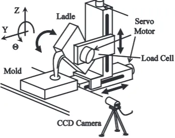
An illustration of the automatic pouring machine used in the present work is shown in Fig. 1. A ladle is transferred by servo motors: Y-axis for back and forward direction and
Z-ax-*1
This Paper was Originally Published in Japanese in J. JFS 88 (2016) 27– 36.
*2
[image:1.595.341.513.636.771.2]is for down and up direction. And a ladle is tilted on Θ-axis. The movable range of each motor is limited; Y-axis 0.4 m, Z-axis 0.6 m, and Θ-axis: ±90˚ (0˚ is defined as a horizontal posture of a ladle). A load cell built into a support member of the ladle, measures the total weight. Each servo system of motors receives velocity references from a Digital Signal Pro-cessor (DSP) and drives based on references. In the present work, ADSP674, a DSP manufactured by Chubu Electric Co. Ltd., was used. The sampling time of the DSP was 0.01 s, which is a sufficiently small term for the pouring process con-trol.
Since the position of the pouring mouth moves by a tilting motion, falling trajectory of outflow liquid varies. To stabilize the falling trajectory, the position of the pouring mouth was fixed by the synchronized control of Y and Z-axes with the tilting motion of Θ-axis18).
Behavior of outflow liquid from a ladle was measured by the image measurement system set at a lateral side of the au-tomatic pouring machine. The measurement system extracts outer shapes of falling liquid from an image captured by a CCD camera, using the edge detection technique, and calcu-lates a falling position of outflow liquid as the center point of the two ends of the outer shape on the measurement posi-tion15). In this paper, STC-CLC33A, a CCD camera manufac-tured by Sentech Co. Ltd., measured behavior of outflow liq-uid, and shot data ware processed by the image processing system based on LabVIEW, the measurement control soft-ware of National Instruments Corp.
The effectiveness of the proposed approach was verified by control experiments using water since a dynamic viscosity coefficient of water is similar to that of molten metal of cast iron and experiments can be executed safely. Although there may be differences in surface tension, in this work we as-sumed all outflows of liquid made similar trajectory of fall-ing.
2.2 Positional relationship between ladle and mold
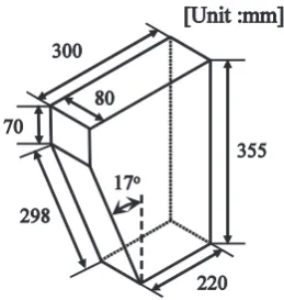
The trapezoidal ladle shown in Fig. 2 was used in this study. The ladle has a shape similar to that of an actual ladle projected from a lateral plane.
Figure 3 shows a positional relationship between a ladle and a mold in the automatic pouring system, including a mold and part of the stage of the machine that must be considered obstacles during the motion control of the ladle, and which are rectangular. The parameters of obstacles were defined as
follows: a distance Dm from a corner point of a mold to the center point of a sprue cup, and a level difference Hs between a surface of a mold and that of a stage. The target of falling position of outflow liquid was the center point of a sprue cup.
3. Mathematical Models of Pouring Process
To achieve the flow rate control and the falling position control of outflow liquid, some process models must be con-structed, namely, the motor model on Θ-axis, the flow rate model, and the free fall model of outflow liquid. This paper touches briefly on these representations because our previous studies show approaches for the flow rate control and the fall-ing position control8,15).
3.1 Motor model on Θ-axis
The relationship between the input voltage uθ and the tilt-ing velocity ω is represented by the followtilt-ing first-order lag system,
dω(t) dt =−
1
Tmθ
ω(t)+Kmθ
Tmθ
uθ(t) (1)
where Tmθ is the time constant, and Kmθ is the gain8). In this paper, Tmθ = 6.00 × 10⁻³ s, and Kmθ = 24.58˚・s−1・V−1. The tilting angle of a ladle θ is derived from a time integration of ω.
3.2 Flow rate model
When the outflow process is shown as in Fig. 4(a), the vol-ume balance equation of pouring with a variation of ω be-comes
q(t)=−dVr(t) dt −
∂Vs(θ(t))
∂θ(t) ω(t) (2)
where q is the outflow rate from a ladle, Vr is the liquid vol-ume over a pouring mouth, Vs is a liquid volvol-ume under a pouring mouth, and h is a height of liquid over a pouring mouth8). h is approximated as
h(t)≈ Vr(t)
A(θ(t)) (3)
where A is a horizontal area at the same height as pouring mouth. Now, if it is assumed that all of outflow comes from upper-side volume of a ladle, the relational equation of h and q is
[image:2.595.103.233.634.771.2] [image:2.595.325.525.636.770.2]q(t)=c h(t)
0
Lf(ha) 2ghbdhb, (0<c≤1, ha=h(t)−hb)
(4)
based on Bernoulli s principle in the steady flow, where Lf is a width at a height ha based on lower end of the pouring mouth, hb is a depth from a liquid surface at the pouring mouth, c is a discharge coefficient identified by comparison of poured weights by experiment and simulation, and g is gravity acceleration 9.81 m・s−2. If a ladle had a rectangular pouring mouth, Lf is constant independent of hb and the rela-tionship of h and q is shown as
q(t)=2
3cLf 2gh3(t) (0<c≤1) (5)
The relationship of q and outflow weight from a ladle w is dw(t)
dt =ρq(t) (6)
where ρ is a density of liquid.
Vs and A of eqs. (2) and (3) are geometry parameters of a ladle, which are derived based on inner geometry. When we use water at room temperature and a trapezoidal ladle, c is 0.659) and ρ is 1.00 × 10³ kg・m−3.
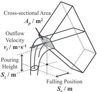
3.3 Free-fall process model of outflow liquid
Figure 5 shows the free-fall process of outflow liquid from a ladle. If it is assumed that a free-fall trajectory of liquid is represented the same as that of mass, the horizontal falling distance Sy can be derived as the product of a horizontal out-flow velocity vt and a falling time Tf from a height Sz to the target point9),
Sy(t)=vt(t0)·Tf(t)=vt(t0) 2gSz(t) (7)
where t0 is the time outflow liquid passed the pouring mouth. If a ladle has a rectangular pouring mouth, vt is represented by dividing q by a cross-sectional area Ap,
vt(t)=β1Lq(h(t))
f ·h(t) +β0=
2
3cβ1 2gh(t)+β0 (vt(t)≥0) (8) where β1 and β0 are adjustment coefficients related to contrac-tion flow at the pouring mouth, derived by calibracontrac-tion
experi-ments. If we use a ladle of Fig. 2 and water, β1 and β0 become 1.82 and −0.179).
3.4 Load cell model
The outflow weight is measured by a load cell built into the pouring system. The dynamics of a load cell is represented by a first-order lag system8),
dwL(t) dt =−
1
TLwL(t)+ 1
TLw(t) (9) where w is outflow weight from a ladle, wL is outflow weight measured by a load cell, and TL is time constant of a load cell. TL is identified by step response using known weight. In this study, TL is 0.05 s8).
4. Falling Position Control of Outflow Liquid Consider-ing Lower Position of PourConsider-ing Mouth
4.1 Estimation of horizontal falling distance
The model-based feedforward control system shown in Fig. 6 was constructed using the above process models. This system has two parts: flow rate control system and falling po-sition control system.
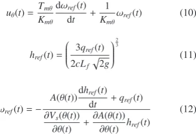
The flow rate controller is realized by Pf−1 and Pmθ−1, in-verse model of motor model Pmθ and flow rate model Pf. By the forward models (1), (2), and (5) shown in Sec. 3, Pmθ−1 is derived as eq. (10) and Pf−1 is derived as eqs. (11) and (12)8,9), Fig. 4 Illustration of pouring process, (a) Parameters in pouring process, (b) Parameters of pouring mouth.
[image:3.595.130.468.76.222.2] [image:3.595.345.503.265.415.2]uθ(t)= Tmθ
Kmθ dωref(t)
dt + 1 Kmθ
ωref(t) (10)
href(t)=
2cL3qref(t) f 2g
2 3
(11)
ωref(t)=−
A(θ(t))dhref(t)
dt +qref(t) ∂Vs(θ(t))
∂θ(t) +
∂A(θ(t)) ∂θ(t) href(t)
(12)
where qref is reference flow rate, href is supernatant liquid height derived from qref, and ωref is reference tilting velocity achieving qref.
The estimation process of horizontal falling distances Ef and Eo is constructed based on free-fall process model Po to achieve control falling position at ro. Since the trapezoidal ladle was used, Ef is expressed as eq. (13) and Eo is expressed as eq. (14).
¯vt(t)=23cβ1 2ghref(t)+β0 (13)
¯Sy(t)=¯vt(t0) 2gSz(t) (14)
As shown in Fig. 6, the falling position of outflow liquid is controlled by the position feedback system of Y-axis Gy which is operated based on position deviation ry between target
fall-ing position ro and estimated falling distance ¯Sy .
4.2 Motion trajectory generation of pouring ladle
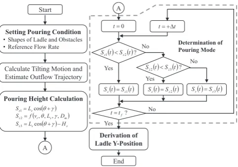
The ladle position such that the position of the pouring mouth becomes the lowest one and also does not collide with obstacles is achieved when the boundary of the ladle attaches with that of obstacles. There were three approaches which achieves such conditions, shown in Fig. 7 if it is assumed that it took a sufficiency short time for liquid to fall from pouring mouth to the target position on the sprue cup and the ladle could move along the boundary19,20). The approaches are de-fined as pouring modes 1, 2, and 3, respectively. The pouring height Sz of each mode was derived from the positional rela-tion of ladle and obstacles, and the estimated falling trajecto-ry of outflow liquid. The definition of each Sz is described in the following paragraphs. Note that the horizontal position of pouring mouth Sy was derived after derivation of Sz.
4.2.1 Mode 1: ladle slides along the upper surface of a mold
In pouring mode 1, a ladle slides along the upper surface of a mold, shown in Fig. 7(a). The height of pouring Sz1 was derived from a shape and a posture of the ladle as eq. (15),
Sz1(t)=Lscos(θ(t)+γ) (15)
where Ls is a length of ladle lateral side and γ is an angle of lateral side.
4.2.2 Mode 2: ladle attached to corner of mold
In pouring mode 2, a ladle is attached to corner point of a mold P during a pouring process. Point Q is obtained as an intersection point between mold upper surface and
[image:4.595.95.290.76.209.2] [image:4.595.127.465.459.627.2]dicular line of pouring mouth. Assuming that Dp is a distance between point P and point Q, then It had the following rela-tionship with position of sprue cup Dm and falling distance of outflow liquid Sy2.
Dm=Sy2(t)+Dp(t) (16)
Sy2 and Dp are functions of Sz2,
Sy2(t)=vt(t) 2
gSz2(t) (17)
Dp(t)=Sz2(t) tan(θ(t)+γ). (18) Equation (16) can be deformed as the quadratic equation of
√Sz2 by substituting eqs. (17) and (18) into it:
tan(θ(t)+γ)· Sz2(t)2+vt(t) 2
g · Sz2(t)−Dm=0. (19)
By solving eq. (19) considering the condition Sz2 ≥ 0, the pouring height of mode 2 Sz2 is derived as
Sz2(t)=
− vt(t)22g + vt(t)22g +4Dmtan(θ(t)+γ) 2
4 tan2(θ(t)+γ) (20)
4.2.3 Mode 3: ladle slides along the upper surface of a machine stage
In this mode, the ladle slides along the upper surface of a machine stage. Thus, the pouring height of mode 3 Sz3 was derived by an approach similar to mode 1,
Sz3(t)=Lscos(θ(t)+γ)−Hs (21)
Sz3 was lower than Sz1 by difference of each upper surface height Hs.
4.2.4 Pouring mode switching
Equations of pouring height were derived to achieve colli-sion avoidance and lower position of pouring mouth, and de-pending on each condition of pouring mode. To keep lower position of pouring mouth throughout the pouring process, pouring mode must be switched based on pouring condition such as flow rate and ladle posture. Therefore, by comparing calculated pouring heights of each mode, pouring mode was switched by applying the following condition,
Sz(t)=
Sz1(t) (Sz1(t)<Sz2(t)) Sz2(t) (Sz1(t)≥Sz2(t), Sz3(t)<Sz2(t)) Sz3(t) (Sz1(t)≥Sz2(t), Sz3(t)≥Sz2(t))
(22)
When pouring mode was switched, ladle postures became the following: Mode 1 and 2 in Fig. 8(a) and Mode 2 and 3 in Fig. 8(b).
The generation process of ladle motion explained in this section is shown in Fig. 9.
5. Effectiveness Evaluation by Control Experiments
5.1 Reference flow rate variation
To verify the effectiveness of the proposed approach, con-trol experiments were executed using an automatic pouring machine. In these experiments, the following three situations
were compared: (I-1) pouring at fixed height without falling position control of outflow liquid; (I-2) pouring fixed at height with falling position control of outflow liquid (conven-tional); (I-3) pouring kept at lower position of pouring mouth (proposed). The target fluid was water.
The initial ladle posture θ(0) was 20˚, and the initial pour-ing height was 0.24 m which were derived from initial condi-tions using eqs. (15)–(22). The falling position of outflow liquid Sy was estimated as 0.00 m when flow rate q equals 0.00 m3・s−1, and therefore the horizontal position of pouring mouth was set directly above. The parameters of obstacles were defined as follows: Dm was 0.20 m: Hs was 0.05 m. Ref-erence flow rate had two terms of constant value: term from 5 s to 7 s was 3.00 × 10⁻⁴ m3・s−1: term from 9 s to 11 s was 4.50 × 10⁻⁴ m3・s−1.
The results of pouring experiments are shown in Fig. 10. In this figure, (a) is reference flow rate; (b) is input voltage to motor on Θ-axis; (c) is titling angle of ladle; (d) and (e) are pouring mouth position on Y and Z-axes; (f) is weight of out-flow liquid measured by load cell; (g) is falling position of outflow liquid on the global axis measured by camera mea-surement system; (h) is pouring mode transition of the pro-posed approach (I-3). The target position of outflow liquid Sy0 is 0 m in Fig. 10(g). In Fig. 10(d)–(g), a black circle is a marker of (I-1); a gray cross is a marker of (I-2); a light gray star is a marker of (I-3). Since the experiments of Fig. 10 (c) agree well with the simulations, tilting angle and tilting ve-locity was controlled on the desired trajectory. The experi-Fig. 8 Timing of pouring mode switching, (a) Mode 1 and 2, (b) Mode 2
and 3.
[image:5.595.305.546.69.197.2] [image:5.595.307.548.236.405.2] [image:5.595.49.289.329.373.2]mental results of poured weight were also in good agreement with the simulation results in Fig. 10 (f). However, the result of (I-3) showed a sharp fluctuation after start of pouring. In the proposed approach, non-smooth motion trajectory of pouring ladle was generated when the pouring mode was switched based on the pouring height. Sharp acceleration and deceleration were induced by non-smooth motion trajectory in the vertical direction at switching timing of pouring mode.
[image:6.595.127.469.73.624.2]It induces quick acceleration on vertical direction when pour-ing mode was switched. Therefore, it seems that inertia forces were induced and another weight variation appeared on mea-surement result of the load cell. This problem is looked for-ward to solve by following ideas: compensation by estima-tion of inertia forces on vertical direcestima-tion; smooth switching of pouring mode. In the measurement result of falling posi-tion in Fig. 10(g), control errors were suppressed within Fig. 10 Experimental results of pouring motion control, (a) Reference flow rate, (b) Input voltage to motor on Θ-axis, (c) Tilting angle of ladle, (d) Pouring
±0.01 m in case (I-2) and (I-3), even when pouring flow rate changed from 5 s to 11 s. Thus, it was shown that the pro-posed approach can control falling position of outflow liquid within same accuracy of the conventional approach.
Figures 11(a)–(c) show the positional relationships be-tween ladle and mold during pouring control of (I-1), (I-2) and (I-3). The black dotted lines mean trajectories of tilting center position and pouring mouth. The outer shapes of ladle are drawn based on tilting angle and positions of Y- and Z-ax-es. The ladle drawings are based on the tilting center position and ladle posture at 0 s, 8 s, 10 s and 16 s, which focus on the times to begin and finish to pour, and of constant flow rate. In Case (I-1) and (I-2), Fig. 11(a) and (b), the space between
ladle and mold became wide in the course of the pouring pro-cess since the height of pouring mouth was kept by the former falling position control. On the other hand, the proposed ap-proach (I-3) achieved a ladle movement that remained at-tached with mold surface. The ladle did not intrude into the mold region, and therefore did not collide with obstacles.
5.2 Repeating same pouring batch
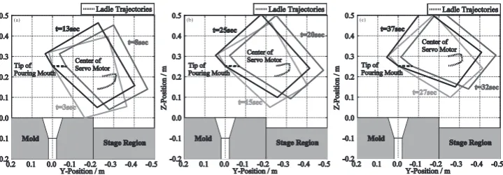
[image:7.595.115.484.254.377.2]In this section, the results are shown that take into consid-eration an actual batch process of pouring in two cases: (II-1) falling position control holding the height of pouring mouth (conventional approach); (II-2) falling position control con-sidering lower position of ladle (proposed approach).
[image:7.595.129.468.439.761.2]Fig. 11 Ladle motions during pouring process, (a) Pouring mouth fixed (without control), (b) Falling position control (constant pouring height), (c) Lower position pouring.
In these experiments, the shape of obstacles were defined as Dm = 0.20 m and Hs = 0.05 m, and initial ladle posture θ(0) of 15˚ was assumed. The reference flow rate was repeated same pattern three times, shown in Fig. 12(a): first batch was from 3 s to 13 s; second batch was from 15 s to 25 s; third batch was from 27 s to 37 s. In one batch process, rise and fall times of flow rate were given as 3 s and constant flow rate was kept for 2 s. The flow rate of flat parts was 2.5 × 10⁻⁴ m3・s−1. Note that forward and backward tilting motions before and after pouring did not include control motion to prevent the effect of sloshing on liquid behavior. The same as in the pre-vious section, for each cases (II-1) and (II-2), the initial height of pouring mouth was determined as the lowest position using the proposed approach with the conditions: q = 0.00 m3・s−1; θ(0) = 15˚. In this paper, the initial height of pouring mouth Sz(0) was 0.25 m. After the first batch, starting height of the next batch was determined by finished position of the previ-ous batch, which can start to pour immediately.
Figure 12 shows a comparison of experimental results: (b) is weight of outflow liquid measured by load cell; (c) and (d) are pouring mouth position on Y and Z-axes; (e) is falling position of outflow liquid on the global axis measured by camera measurement system; (f) is pouring mode transition of the proposed approach (II-2). Also, in Fig. 12(b)–(e), a black circle is a marker of (II-1); a light gray cross is a mark-er of (II-2). Figure 12(e) shows that falling position control was achieved for each batch process by both approaches. Ad-ditionally, control errors were minimized to less than ±0.015 m when flow rate became constant.
Figures 13 and 14 show positional relationships between ladle and obstacles. In case (II-1), the conventional approach, the space between ladle and obstacles became wide in the
course of the pouring process since the pouring mouth was kept at the initial height. If an adjustment ladle motion were introduced, the space may be minimized but cycle time of the pouring process may become longer. On the other hand, in the proposed approach (II-2) shown in Fig. 14, the height of pouring mouth was kept the lowest position of ladle during the pouring process. There were no collisions in the batch processes.
6. Conclusion
This paper shows a novel approach of motion trajectory generation of pouring ladle that achieves falling position con-trol of outflow liquid with lower position of pouring mouth. In this approach, ladle motion equations were derived for three situation based on positional relationships between la-dle and obstacles, and falling trajectory of outflow liquid. In addition, the switching condition was defined to switch among three pouring modes and keep the lowest position of ladle. Finally, the effectiveness of the proposed approach was verified by pouring experiments using water. It was confirmed that the proposed approach achieved falling position control of outflow liquid with high precision.
REFERENCES
1) K. Terashima: SOKEIZAI 39 (1998) 1. 2) Y.S. Lerner: Mod. Cast. 93 (2003) 44.
3) J. Sato and K. Yoshida: Industrial heating 29 (1992) 19.
4) K. Shinohara and H. Hiroyuki: J. Soc. Automot. Eng. Jpn. 46 (1992) 79.
[image:8.595.122.482.70.195.2] [image:8.595.114.485.237.354.2]5) S. Tokai, K. Yamabayashi and Y. Hashimoto: J. JFS 82 (2010) 47. 6) Y. Kuriyama, M. Maeda, K. Yano and Y. Michioka: J. JFS 82 (2010) Fig. 13 Ladle motion in repeated pouring (Case II-1), (a) 1st motion, (b) 2nd motion, (c) 3rd motion.
531.
7) R. Kusakabe and M. Yamada: Proc. 54th Japan Joint Automatic Control Conference (2011) p.1714.
8) Y. Noda and K. Terashima: Trans. Jpn. Soc. Mech. Eng. Ser. C 72 (2006) 3147.
9) Y. Noda, R. Fukushima and K. Terashima: Trans. Jpn. Soc. Mech. Eng. Ser. C 78 (2012) 3446.
10) E. Tabatabaei: Ductile Iron News (2000) p.1.
11) W. Pflug and E. Tabatabaei: Fondry Management & Technology 130 (2002) 10.
12) S. Paranjape and P.D. Chaubal: Metalworld (2010) 24.
13) H. Doisy: Proc. 62nd Indian Foundry Congress, India (IIF, 2014) p.18. 14) W. R. Pflug: Proc. 62nd Indian Foundry Congress, India (IIF, 2014)
p.26.
15) V. I. Dubodelov, V. K. Pogorsky and M. S. Goryuk: Proc. 9th Interna-tional Symposium on Science and Processing of Cast Iron, Egypt (TTP, 2009) p.481.
16) K. Iwata, T. Choh and M. Inoue: Tetsu-to-Hagané 68 (1982) 2461. 17) C. Samnang, Y. Noda, K. Terashima and K. Hashimoto: Proc. European
Metallurgical Conference 2007 Vol.4, Germany (GDMB, 2007) p.1899. 18) K. Terashima, K. Yano, Y. Sugimoto and M. Watanabe: Proc. 10th IFAC symposium on Automation in Mining, Mineral and Metal Processing, Japan (IFAC, 2001) p.182.
19) A. Ito, Y. Noda and K. Terashima: Proc. IEEE Multi-Conference on System and Control, Croatia (IEEE, 2012) p.246.