Grain Orientation and Texture Evolution in Pure Titanium Lap Joint
Produced by Friction Stir Welding
Hong Liu
1, Kazuhiro Nakata
1, Naotsugu Yamamoto
2and Jinsun Liao
2 1Joining and Welding Research Institute, Osaka University, Ibaraki 567-0047, Japan 2Technology Development Headquarters, Kurimoto Ltd., Osaka 559-0021, Japan
Pure titanium lap joints were produced by friction stir welding, and the grain orientation and texture evolution were investigated as well as the mechanical property of the lap joint. The grain orientation changes obviously after welding, and the strong P1texture formed in the stir zone
suggests that the metal flow can be characterized by a simple shear deformation. The shear plane in the center and bottom parts of the stir zone is shown to be a spherical crown surface, which is nearly similar to the bottom shape of the probe. The vertical flow of stirred metal is slight and it may be a reason why the welding condition is narrow. The hardness in the stir zone is distinctly higher than that in the base metal due to the grain refinement after FSW, and the shear tensile strength is so high that the fracture happens at the base metal, resulting from both the hardness increase in the stir zone and the sufficient width of lap zone. [doi:10.2320/matertrans.M2010242]
(Received July 16, 2010; Accepted August 20, 2010; Published October 6, 2010)
Keywords: friction stir welding, pure titanium, lap joint, grain orientation, texture evolution
1. Introduction
Titanium and its alloys exhibiting high specific strength and excellent corrosion resistance have been employed in many important industrial fields, and their welding and joining techniques have become greatly important in order to apply these materials to various products. However, the fusion welding of titanium and its alloys is extraordinarily arduous because of surface oxidation and shape distortion. Friction stir welding (FSW), an innovative solid-state welding process invented in 1991 by Thomas et al.,1) has received much attention due to the avoidance of solidification problems associated with the fusion welding techniques.2–5)It has been successfully applied to the low-melting metals,6–16) and also the high-melting metals in recent years as a result of continuous development of FSW technique.17–34)A great number of researches dealing with the FSW of titanium and its alloys have been made to clarify the microstructure and its formation mechanism in the stir zone.24–34) Besides, the previous works have mainly been concentrated on the butt joint and the information on lap joint of pure titanium is relatively rare. The present authors have investigated the influences of welding parameters on defect in the lap joint of pure titanium, and found that the position-controlled FSW is favorable to the lap joining of pure titanium.35)In this study, the grain orientation and texture evolution in pure titanium lap joint were examined intensively using the electron backscattering diffraction, and the mechanical property of the lap joint was also evaluated.
2. Experimental
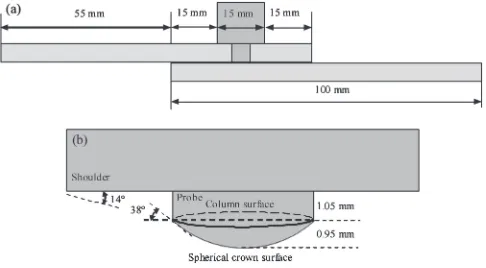
The material used in this study is the grade 2 commercially pure titanium sheet with 2 mm thickness, and has chemical compositions (mass%) of 0.01 C, 0.03 Fe, 0.01 N, 0.1 O, 0.001 H and Ti bal. The friction stir welding of lap joint was carried out using a sintered WC-Co tool (tilted at 3from the vertical) consisting of a probe of 2 mm in length and 6 mm in diameter, and a shoulder of 15 mm in diameter. The
schematic illustrations of the pure titanium lap joint and the probe shape are shown in Fig. 1. During FSW, a position control system was employed and the plunge depth was controlled to be about 2.3 mm under a plunging force of 19.6 kN. The rotation speed was varied from 150 to 300 rpm, and the welding speed was at a range of 50 to 125 mmmin1 in this investigation. The water cooling and argon shielding systems were utilized to cool the welding tool and minimize surface oxidation.
After FSW, the lap joint was cross-sectioned by a wire electrical discharge cutting machine (HSC-300; Brother Ind. Ltd.). The cross-section was mechanically polished using water abrasive paper and finally with 1mmdiamond paste. The polished cross-section was etched in a solution compris-ing of hydrofluoric acid, nitric acid and distilled water at a volume ratio of 1 : 1 : 8, and examined with an optical microscope (OM; VH-Z100R; Keyence Corp.). The electron backscattering diffraction (EBSD) was employed to analyze the grain orientation and texture evolution, using a scanning electron microscope (JSM-6400; JEOL Ltd.) incorporated with a TexSEM Laboratories (MSC-2200; TexSEM Labo-ratories Inc.). The sample for EBSD was electro-polished in a solution containing perchloric acid, n-butyl alcohol and
Fig. 1 Schematic illustrations of: (a) the pure titanium lap joint; (b) the probe shape.
[image:1.595.306.549.326.460.2]methanol at a volume ratio of1 : 7 : 10at room temperature with an applied potential of 25 V. The scanning step of 2.0mmand the average confidential index (CI) ranging from 0.45 to 0.55 was obtained in EBSD analysis. The hardness distribution (AAV-500; Akashi) at the cross-section of lap joint was measured under a load of 0.98 N for a dwell time of 15 s with an interval of 0.25 mm both along the horizontal direction and the vertical direction. The shear tensile test (Instron-5500R; Instron Corp.) was performed using the specimen of 20 mm in width and 155 mm in length, at room temperature with a servohydraulic load frame operating at a constant crosshead velocity of 1 mmmin1. It is necessary to say that the weld lengths for the microstructure analysis and the shear tensile test were respectively about 90 and 130 mm. The specimens for the microstructure analysis and the shear tensile test were cut in the center region of the welds far from the starting point, and three specimens for the shear tensile test were made.
3. Results and Discussion
3.1 Optimum welding condition
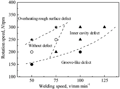
The optimum welding condition for lap joint of pure titanium is given in Fig. 2. The lap joints without defect are obtained at rotation speed of 250 rpm and welding speed of 75 mmmin1, and at rotation speed of 200 rpm and welding speed of 50 mmmin1. It should be pointed out that the position control is realized by changing the axial force automatically with the plunge depth altering during FSW. When the excessive heat input is employed (i.e. with higher rotation speed and lower welding speed), the plunge depth increases and then the axial force starts to decrease correspondingly. However, the obtuse response speed of axial force likely results in the partial plunging of the tool and the overheating rough surface defect occurs accordingly (it may be improved by a strict position control system). Furthermore, the inner cavity defect or groove-like defect is present at lower heat inputs (i.e. with lower rotation speed and higher welding speed). The detailed morphologies of the defects have been described elsewhere.35) It can be found from Fig. 2 that the optimum welding condition for the lap joining of pure titanium is very narrow in this work, and this
is probably related to the metal flow or deformation behavior in the lap joint, which is strongly influenced by the welding tool.
3.2 Grain orientation and texture evolution
The EBSD maps in various regions of the lap joint at rotation speed of 250 rpm and welding speed of 75 mmmin1 are shown in Fig. 3 together with a low
magnification overview of the cross-section of the lap joint, where the regions for the EBSD analysis are denoted. The AS, RS, WD, TD and ND are the advancing side, retreating side, welding direction, transverse direction and normal direction, respectively. The SP is the shear plane induced by the welding tool during FSW, and the SPN is the shear plane normal. The grains in the EBSD maps are colored in terms of the crystal directions relative to the WD. It is obvious from the overview that the lap joint was composed of the base metal (BM), the thermo-mechanically affected zone (TMAZ) and the stir zone (SZ). The upper and bottom titanium plates are lap-joined together in the bottom part of the joint, and thus this region is defined as the lap zone (LZ) shown in the overview. It can also be seen that the shape of SZ is affected by the geometrical form of the welding tool. The boundary between the TMAZ and SZ can be described as a straight line in the top part of the joint, which aligns about 14to horizon.
A truncated cone,22,28,29)having a diameter of shoulder in the top and column part of the probe in the bottom with a height of column part, can be confirmed according to the rotation of tool. The angle, between the TMAZ-SZ boundary in the top part of the joint and the horizontal line, is nearly accordant with the acute angle between the cone surface and base plane (see Fig. 1(b)). In the center and bottom parts of the joint, the TMAZ-SZ boundary appears as circular arc shape, which is similar to the bottom shape of the probe. The angle between the SPN and TD is about 52 in the center part of the joint,
and gradually increased to be 70 in the LZ (i.e. the bottom
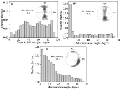
part of the joint), as can be seen from Fig. 3. It can be accepted that the boundary induced by deformation generally accords with the most stressed plane.36)So the shear plane during FSW is nearly parallel to the TMAZ-SZ boundary, which has been discussed by Mironov et al.22,29) It is commonly believed that the angle between the SPN and TD at the AS is roughly equal to that at the RS. And the angle value is also considered to be adequate in the center part of the SZ in view of the tool rotation during FSW, which has been reported by Mironov et al.22,29) These angle data are used to rotate the pole figures in order to understand the texture evolution in the SZ, as described later. Moreover, it is clear from the EBSD maps that the microstructure in the SZ is different from that in the BM. The BM can be characterized by coarse-equiaxed grains, while the microstructure at the SZ can be depicted as fine-equiaxed grains. The fine-equiaxed grain structure is supposed to result from the dynamic recrystallization, because SZ has experienced heavy plastic deformation at a relatively high temperature.30) Figure 4 presents the misorientation distributions and (0002) pole figures in the BM, TMAZ-AS and SZ-AS (shown in Fig. 3). A texture with a bimodal distribution of basal plane is represent in the BM, where many high-angle grain bounda-ries (misorientation angle 15) and some low-angle grain
Fig. 2 Optimum FSW condition for the lap joint of pure titanium.
[image:2.595.53.284.595.767.2]boundaries (2 <misorientation angle<15) were
ob-served. In the TMAZ-AS, the original bimodal distribution texture disappeared partly, and a sharp low-angle peak appeared in misorientation distribution. In the SZ-AS, the
crystallographic orientation is obviously different from that in the BM and TMAZ, and the intensity of texture increased sharply. Additionally, there are also many low angle boundaries in the SZ-AS.
Fig. 4 Misorientation distributions and (0002) pole figures: (a) BM; (b) TMAZ-AS; (c) SZ-AS.
Fig. 3 A low magnification overview of the cross-section of the lap joint at 250 rpm and 75 mmmin1and EBSD maps in various regions
[image:3.595.100.497.73.355.2] [image:3.595.100.494.404.697.2]Figure 5 gives the real pole figures and rotated pole figures of various regions in the SZ (seen from Fig. 3). The orientation data from the EBSD maps are arranged as (0002) and (10110) pole figures. The stars on the rotated pole figures represent the positions of pure titanium P1 texture under
ideal simple shear deformation, which has been determined by Mironov et al.,29) Beausir et al.37) and Li et al.38) The real pole figures are rotated by transforming the original reference frame into the conventional reference frame for simple shear in order to compare the texture obtained in this study with that produced at ideal simple shear deformation, and the approach for the texture rotation has been detailedly discussed by Mironov et al.22,29)It should be declared that the horizontal direction and vertical direction correspond to the shear direction (SD) and the SPN after rotation. The rotated pole figures are acquired through rotations described as follows: In the center part of the SZ, the real pole figures in I region were rotated by80around the ND followed by 38 around the TD, and the figures in II region were
rotated by 55 around the ND followed by 38 around
the TD, while the figures in III region were only rotated by 38 around the TD; In the bottom part of the SZ, the real
pole figures in IV region were rotated by45 around the
ND followed by20 around the TD, and the figures in V region were only rotated by20 around the TD, while the figures in VI region were rotated by +30 around the ND
followed by20 around the TD. As shown in the rotated
pole figures, the texture in the center and bottom parts of the SZ is identical to the P1 texture and the P1 texture from AS
to RS reasonably match the rotation of the SD in the SZ according to the adopted angles between the SPN and the TD indicated in the EBSD maps. The formation of P1texture
in the SZ during FSW is mainly ascribed to the prism slip of f10110gh11220i caused by the simple shear deformation, which has been reported recently by Mironov et al.29)and Kniplinget al.33)Therefore, the deformation behavior in the lap joint of pure titanium is also associated with the simple shear deformation and the shear plane in the region is shown to be a spherical crown surface (nearly similar to the bottom shape of the probe).
In the previous works, the texture evolution in the center part of the SZ is described.22,28,29)The center part of the SZ exhibits a truncated cone shape and the metal flow can be described in terms of simple shear, whereas the deformation behavior in the bottom part of the SZ has not been determined owing to the occurrence of complicated metal flow in the butt joint resulted from the restriction of backing plate. In this work, the deformation behavior in the bottom part of the SZ is clarified for the first time, which is helpful to comprehensively understand the deformation mechanism (or metal flow) in the SZ of lap joint during FSW. As mentioned above, the metal flow is induced by the simple
[image:4.595.101.496.81.439.2]shear deformation around the welding probe. However, the P1 texture in Fig. 5 slightly deviates from the vertical line
and it means that the SD is not ideally horizontal. The reason of deviation is probably consistent with the approximate estimation of the SD/SPN under the complex metal flow of SZ22)and the occurrence of slight vertical flow during FSW. Thus, it can be concluded that the vertical flow in the SZ is not intense and the vertical flow of the interface between top and bottom titanium plates is not sufficient. As a result, it may lead to the narrow welding condition for the lap joining of pure titanium. The probe with threads is beneficial to the vertical flow of stirred metal, which maybe enlarge the optimum welding window.
3.3 Hardness and shear tensile strength
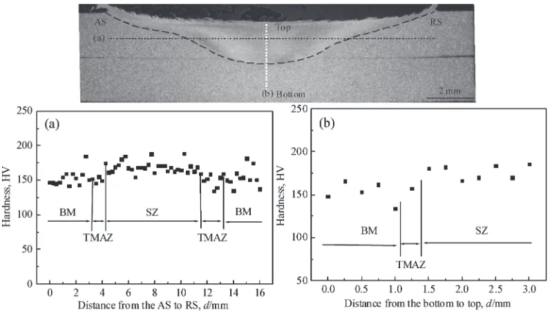
Figure 6 shows the hardness profiles in the lap joint at rotation speed of 250 rpm and welding speed of 75 mmmin1 both along the horizontal direction (dotted black line) and the vertical direction (dotted white line). While the hardness distribution is somewhat scattered, the average value of hardness in the SZ is distinctly higher than that in the BM. Table 1 gives the average grain size and hardness in the BM and SZ as well as the failure load and fracture position of shear tensile specimen. It can be seen that the average hardness and grain size in the BM are about 153 HV and 22mm, and the hardness and grain size in the SZ are 173 HV and 6mm, respectively. Therefore, the increase of hardness in the SZ can be considered to result from the grain refinement. It can also be found from Table 1 that the average failure load was up to about 14.5 kN and the fracture location of shear tensile specimen is at the BM. The fracture at the BM is probably attributed to the two aspects, i.e. the hardness increase in the SZ, which means that the strength in the SZ is higher than that in the BM, and the enough width of LZ,35)which provides the sufficient bonding strength and thus prevents the fracture at the LZ.
4. Conclusions
Pure titanium plates were lap-joined using friction stir welding, and the grain orientation, texture evolution and mechanical property of the lap joint were investigated. The results can be summarized as follows.
(1) The optimum welding condition for the lap joining of pure titanium plates is quite narrow. The shape of SZ is obviously influenced by the geometrical form of the welding tool. The TMAZ-SZ boundary in the center and bottom parts is shown to be a spherical crown surface, which is nearly similar to the bottom shape of the probe.
(2) The grain orientations in the TMAZ and SZ are remarkably different from that in the BM. The strong P1 texture is formed in the SZ, suggesting that the
metal flow at this zone is induced by a simple shear deformation, which is mainly caused by the prism slip. The slight vertical flow of stirred metal may be a reason why the optimum welding condition is narrow. (3) The hardness in the SZ is distinctly higher than that in
the BM due to the grain refinement in the SZ. The hardness increase in the SZ and the enough width of LZ provides the sufficient bonding strength for the lap joint, so that the fracture of specimen occurs at the BM during shear tensile test.
[image:5.595.99.497.71.296.2]Fig. 6 Hardness profiles in the lap joint along: (a) the horizontal direction from the AS to RS; (b) the vertical direction from the bottom to top.
Table 1 Grain size, hardness, average failure load and fracture position of the lap joint.
Grain size in the BM (mm)
Grain size in the SZ (mm)
Hardness in the BM
(HV)
Hardness in the SZ (HV)
Average failure load
(kN)
Fracture location
[image:5.595.304.549.384.433.2]Acknowledgments
The authors give the acknowledgement to Professor H. Fujii for the helpful discussions. And they are also grateful to Assistant professor T. Tsumura and Dr. Y. C. Chen for the kindly technical assistance and useful advice.
REFERENCES
1) W. M. Thomas, E. D. Nicholas, J. C. Needham, M. G. Murch, P. Templesmith and C. J. Dawes: International Patent Application No. PCT/GB92/02203, (1991).
2) R. S. Mishra and Z. Y. Ma: Mater. Sci. Eng. R50(2005) 1–78. 3) C. J. Dawes and W. M. Thomas: Weld. J.75(1996) 41–45. 4) C. G. Rhodes, M. W. Mahoney, W. H. Bingel, R. A. Spurling and C. C.
Bampton: Scr. Mater.36(1997) 69–75.
5) M. A. Sutton, B. Yang, A. P. Reynolds and R. Taylor: Mater. Sci. Eng. A323(2002) 160–166.
6) J. Q. Su, T. W. Nelson, R. Mishra and M. Mahoney: Acta Mater.51
(2003) 713–729.
7) H. S. Park, T. Kimura, T. Murakami, Y. Nagano, K. Nakata and M. Ushio: Mater. Sci. Eng. A371(2004) 160–169.
8) S. H. C. Park, Y. S. Sato and H. Kokawa: Metall. Mater. Trans. A34
(2003) 987–994.
9) K. Nakata, Y. G. Kim, H. Fujii, T. Tsumura and T. Komazaki: Mater. Sci. Eng. A437(2006) 274–280.
10) M. Peel, A. Steuwer, M. Preuss and P. J. Withers: Acta Mater.51
(2003) 4791–4801.
11) Kh. A. A. Hassan, A. F. Norman, D. A. Price and P. B. Prangnell: Acta Mater.51(2003) 1923–1936.
12) S. H. C. Park, Y. S. Sato and H. Kokawa: Scr. Mater.49(2003) 161– 166.
13) L. Yu, K. Nakata and J. Liao: J. Alloy. Compd.480(2009) 340–346. 14) J. Liao, N. Yamamoto and K. Nakata: Metall. Mater. Trans. A 40
(2009) 2212–2219.
15) N. Yamamoto, J. Liao and K. Nakata: J. Jpn. Inst. Met.72(2008) 538– 543.
16) P. B. Prangnell and C. P. Heason: Acta Mater.53(2005) 3179–3192.
17) J. Liao, N. Yamamoto, H. Liu and K. Nakata: Mater. Lett.64(2010) 2317–2320.
18) A. P. Reynolds, W. Tang, T. Gnaupel-Herold and H. Prask: Scr. Mater.
48(2003) 1289–1294.
19) R. Ayer, H. W. Jin, R. R. Mueller, S. Ling and S. Ford: Scr. Mater.53
(2005) 1383–1387.
20) K. H. Song, H. Fujii and K. Nataka: Mater. Design30(2009) 3972– 3978.
21) H. Fujii, L. Cui, N. Tsuji, M. Maeda, K. Nakata and K. Nogi: Mater. Sci. Eng. A429(2006) 50–57.
22) S. Mironov, Y. S. Sato and H. Kokawa: Acta Mater.56(2008) 2602– 2614.
23) H. K. D. H. Bhadeshia and T. Debroy: Sci. Technol. Weld. Joining14
(2009) 193–196.
24) A. J. Ramirez and M. C. Juhas: Mater. Sci. Forum426–432(2003) 2999–3004.
25) W. B. Lee, C. Y. Lee, W. S. Chang, Y. M. Yeon and S. B. Jung: Mater. Lett.59(2005) 3315–3318.
26) L. Zhou, H. J. Liu, P. Liu and Q. W. Liu: Scr. Mater.61(2009) 596– 599.
27) Y. Zhang, Y. S. Sato, H. Kokawa, S. H. C. Park and S. Hirano: Mater. Sci. Eng. A488(2008) 25–30.
28) A. P. Reynolds, E. Hood and W. Tang: Scr. Mater.52(2005) 491–494. 29) S. Mironov, Y. S. Sato and H. Kokawa: Acta Mater.57(2009) 4519–
4528.
30) H. Fujii, Y. Sun, H. Kato and K. Nakata: Mater. Sci. Eng. A527(2010) 3386–3391.
31) K. Reshad Seighalani, Givi. M. K. Besharati, A. M. Nasiri and P. Bahemmat: J. Mater. Eng. Perform.18(2009) 1–8.
32) D. G. Sanders, M. Ramulu, E. J. Klock-McCook, P. D. Edwards, A. P. Reynolds and T. Trapp: J. Mater. Eng. Perform.17(2008) 187–192. 33) K. E. Knipling and R. W. Fonda: Scr. Mater.60(2009) 1097–1100. 34) H. J. Liu, L. Zhou and Q. W. Liu: Mater. Design31(2010) 1650–
1655.
35) H. Liu, K. Nakata, N. Yamamoto and J. Liao: Sci. Technol. Weld. Joining15(2010) 428–432.
36) F. J. Humphreys and P. S. Bate: Acta Mater.54(2006) 817–829. 37) B. Beausir, L. S. To´th and K. W. Neale: Acta Mater.55(2007) 2695–
2705.