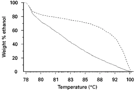
Figure 1 Vapour}liquid equilibrium: ethanol}water, 760 mmHg. Continuous line, bubble point line; dashed line, dew point line.
WHISKY: DISTILLATION
D. S. Pickerell, Maker’s Mark Distillery, Loretto, KY, USA
Copyright^ 2000 Academic Press
Introduction
Grain fermentation yields a water-based liquid mix-ture commonly referred to as distiller’s beer. This beer will typically contain between 5 and 9% by weight ethyl alcohol, 6}8% by weight residual grain solids, and a very small quantity of other compounds known as fusel oils. These fusel oils, also known as congeners, are primarily higher alcohols that are sol-uble in ethyl alcohol but only partially solsol-uble in water. The congeners contribute to the taste and aroma of whisky and are not typically removed in a single-column distillation.
All separation technologies exploit some difference between items in a mixture or solution in order to cause them to separate. These differences may be physical, chemical or electrical in nature. In particular, distillation takes advantage of the differ-ence in boiling points to separate soluble liquids from one another. Not all liquid solutions may be eco-nomically separable by distillation for a variety of reasons. For example, one or more of the liquid components may not appreciably volatize, or the change in the concentrations of the components be-tween the gas phase and the liquid phase may be so small that the process becomes impractical. It may even happen that there is no change in the composi-tion whatsoever.
In general, during distillation of completely miscible liquids, the component with the higher boiling point moves toward the bottom of the still while the component with the lower boil-ing point moves toward the top. In whisky produc-tion, water boils at a higher temperature while ethyl alcohol boils at a lower temperature. As a result, distillation has an added beneRt as the separation technique of choice, because the grain residue is naturally carried to the bottom of the still along with the water. If the still is properly designed, the concentration of alcohol in the still bottoms should be negligible and the discharge from the bottom of the still will contain all of the unwanted grain residues and the excess water.
Vapour
^
Liquid Equilibrium
In order to understand what happens during the dis-tillation process, we need to address the topic of vapour}liquid equilibrium. For the purpose of this discussion, we will consider the case of distilling a mixture of water and ethyl alcohol at a constant pressure of 1 atm.Figure 1shows the vapour}liquid equilibrium curves for this mixture. It should be noted that the concept of a single boiling point is invalid for this type of solution. The lower line is referred to as the bubble point line. At a given concen-tration of ethyl alcohol in a liquid mixture of ethanol and water, the bubble point line indicates the temper-ature at which theRrst bubble of vapour forms as the solution is heated. The upper line is called the dew point line. At a given concentration of ethanol in a vapour mixture of ethanol and water, the dew point line indicates the temperature at which theRrst drop of condensate is formed as the mixture is cooled.
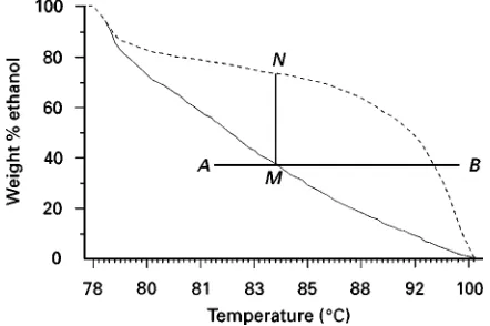
Figure 2 Vapour}liquid equilibrium: ethanol}water, 760 mmHg. Continuous line, bubble point line; dashed line, dew point line.
[image:2.568.295.513.534.681.2]Figure 3 Vapour}liquid equilibrium: ethanol}water, 760 mmHg. Continuous line, bubble point line; dashed line, dew point line.
Figure 4 Vapour}liquid equilibrium: ethanol}water, 760 mmHg. Continuous line, bubble point line; dashed line, dew point line.
Figure 5 Vapour}liquid equilibrium: ethanol}water, 760 mmHg. Continuous line, bubble point line; dashed line, dew point line.
temperature reaches about 833C where the heating line intersects the bubble point line at pointM. At this point, the Rrst bubble of vapour forms, but because the ethanol vaporizes more easily than the water at this point, the vapour phase is enriched in ethanol. The concentration of ethanol in this Rrst bubble of vapour is found at point N, about 75% ethanol by weight (Figure 4). As the mixture continues to heat up, eventually point Pis reached at about 873C. At this point, the mixture is boiling. The liquid still in the pot has a concentration of about 17%, as indicated by point 0, while the total vapour concentration is represented by point R at about 64% ethanol (Fig-ure 5). The solution can continue to be heated until the heating line intersects with the dew point line at pointT. At this point there is only one drop of liquid left in the pot and its concentration is found at point S to be about 2% ethanol by weight. If all of the vapour from this experiment was collected, its con-centration would be found at point T } approxim-ately 40% by weight ethanol}right back where we
started from, only hotter. The vapour could then be superheated to 993C at point B, but no further cha-nges in ethanol concentration would occur.
[image:2.568.52.273.535.682.2]Figure 6 Vapour}liquid equilibrium: ethanol}water, 760 mmHg. Continuous line, bubble point line; dashed line, dew point line.
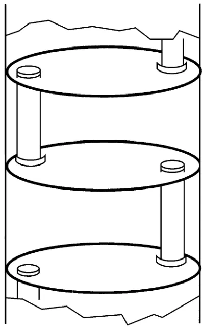
Figure 7 Cut-away of typical distillation column.
If a concentration greater than that represented by pointNis desired, a single pot cannot accomplish the task (Figure 6). Suppose, however, that we set up an apparatus whereby we constantly feed theRrst pot as described earlier, but now we condense the product vapour and put it in another pot where it can be distilled a second time. The concentration of the va-pour from the second pot is represented by pointX, about 82% by weight ethanol. It can be seen that adding more pots to this scheme would result in higher and higher concentrations of ethanol in the product. There is, however, a limit to this approach. As the bubble point and dew point lines get closer together, the increase in ethanol concentration per added pot decreases. Eventually, these two lines touch. The point at which these lines touch is called an azeotrope. Azeotrope is a Greek word meaning ‘to boil together’. Literally, at this point additional separation by conventional two-phase distillation is impossible because the liquid- and vapour-phase con-centrations are identical. In fact, even getting close to the azeotrope requires more advanced distillation practices than those commonly used in whisky produc-tion.
By anology, it can be seen that the problem of recovering the residual ethanol from the still bottoms can also be accomplished through the use of addi-tional distillation stages. In practice, however, the distillation column is a more efRcient method of ac-complishing these distillation tasks than multiple pot stills. Single malt Scotch whisky makes use of mul-tiple pot stills in the production of theirRnal distillate in a manner similar to that described above.
The Continuous Beer Still
The Rrst distillation element in a multicomponent whisky distillation system is commonly referred to as
the beer still. The beer still consists of a cylindrical shell and number of evenly spaced trays connected by pipes called downcomers.Figure 7shows a cut-away view of the inside of a typical beer still. The liquid in the still moves across the trays and down the down-comers. The vapour in the still moves up the column through holes in the tray and through the liquid. The pressure of the vapour under each tray must be great enough to allow the vapour to pass through the holes and through the liquid to the next level up the tray without allowing the liquid to drip through the holes (Figure 8). Each time the vapour passes through the liquid, the vapour gains ethanol concentration while the liquid loses ethanol concentration. One tray is roughly equal to one distillation in a pot similar to that discussed earlier. Technically, the vapour con-denses in the liquid of the tray above it, and gives off its heat of vaporization. This heat of vaporization in turn revaporizes a corresponding volume of vapour which is richer in ethanol.
[image:3.568.300.498.57.380.2]Figure 8 Typical plate flow detail.
the stripping section, because here the residual alco-hol is essentially stripped from the feed stream so that the still bottoms have a negligible presence of ethanol. The still must be designed not only to produce a spirit of the desired proof, but also to limit base losses. Typically, the stripping section has about 16}20 plates. The plates in this section must be designed to minimize the likelihood of fouling due to the grain residue being present here. Almost exclusively, sieve trays are used for this purpose because they have larger, less complex vapour openings and wider toler-ances to help prevent plugging with grain particles. The space between the trays must also be sufRciently wide to prevent foam and other entrained liquid on one tray from inSuencing the tray above it.
It is possible for grain particles in the feed to be entrained in and carried upwards by the vapour pass-ing through the feed tray. This can happen on any tray in the stripping section, but it is most critical on the feed tray. Various approaches have been utilized to minimize this problem; almost all are mechanical alterations to the still itself. The most common de-entrainment device is the use of one additional sieve tray immediately above the feed tray.
The rectifying section of the still is the part that is above the feed tray. In this section, the alcohol is concentrated to the desired product proof. Typically, the rectifying section has between two andRve plates. The plates in this section are designed to cause more efRcient commingling of the vapour with the liquid as the vapour passes through the plate. Since solids are no longer an issue, the contacting mechanisms can be
more intricate and tolerances closer in this section. The plates in this section may also be more closely spaced because foaming and entrainment are much less of a problem here than in the stripping section.
The Beer Heater
As a rule of thumb, the conditions of the feed stream to the still should match, as closely as possible, the conditions on the tray to which the feed is introduced. It has already been noted that the ethanol concentra-tion of the feed stream is generally between 5 and 9% by weight. The concentration can be closely predicted from heat and material balance calculations where no empirical data exist for a given feed stream. It has also been noted that the feed tray is generally near the 18th plate. The feed tray location can also be pre-dicted from detailed will design calculations. The only problem that remains, then, is the feed temper-ature. When fermentation is complete, the beer temperature is generally about 343C. The feed tray liquid temperature should be about 933C. Since the vapour from the still generally has to be cooled and condensed, it provides a convenient source of heat to pre-heat the beer. Usually, the beer feed is passed through a shell and tube-type heat exchanger with large diameter tubes to help alleviate plugging. The vapours from the still are on the shell side of the exchanger.
The condensate from the beer heater is generally returned to the still as reSux. ReSux is the liquid returned to the top of the still. It alters the number of trays required to perform the desired degree of separ-ation as well as the tower cross-sectional area and the heating and cooling loads required for vaporization and condensation. ReSux is generally referred to as a ratio of the liquid returned to the still versus prod-uct collected. As the reSux ratio goes up, the number of trays required to perform the separation goes down, but the requisite heating and cooling loads go up. At inRnite reSux, the minimum number of trays is achieved, but the maximum heating and cooling loads are required. At minimum reSux, an inRnite number of trays is required for the separation, but minimum energy requirements are achieved. An opti-mum reSux ratio can be calculated and the beer heater can be designed to provide that reSux.
on the type of whisky being produced, there are generally governmentally prescribed maximum ethanol concentrations which may be permitted dur-ing the distillation process. In the case of bourbon, the US Bureau of Alcohol, Tobacco, and Firearms pre-scribes that the distillate may be taken from the still at no higher than 160 proof (80% ethanol by volume). Of utmost importance, however, are the organoleptic considerations which go into the production par-ameters for the whisky. Product taken off at a lower proof retains more of the grain character, while product taken off at a higher proof tends to have less of the grainSavour constituents.
The Doubler
Many distillers utilize a doubler in their whisky distil-lation process. The doubler is basically a pot still, like the one discussed earlier. The doubler acts as one additional distillation stage. It is used in practice for Rnal proof adjustment and for product quality en-hancement. There are two fundamentally different ways of operating the doubler. TheRrst is called true double distillation. In true double distillation, the still vapours generally pass through the beer heaterRrst, and then one or more condensers, so that the product is completely condensed back to a liquid form. This liquid is then charged to the doubler where it is heated with steam coils and re-vaporized. The vapour from the doubler is then condensed again and taken off as product.
The doubler can also be operated as a thumper. In this case, the doubler is Rtted with a large sparger. The doubler is charged with liquid to a level just above the sparger. The liquid is typically de-mineralized water or the low proof tails cut from a previous distillation.The vapour from the stillRrst passes through the beer heater then through the spar-ger in the doubler where it bubbles through the liquid. As the vapour passes through the liquid in the doub-ler, itSash condenses and gives off its heat of vapor-ization which, in turn, revaporizes a corresponding volume of vapour which is richer in ethanol. The thumper gets its name from the sound made as the vapour condenses while passing through the liquid. Finally, the ethanol-enriched vapour passes through one or more condensers and is taken off as product.
Reboilers
Most beer stills are heated by direct steam injection from a low pressure steam sparger located in the base of the still. A reboiler is a type of heat exchanger which permits the use of higher pressure steam than a steam sparger will allow. There are several
advant-ages to using a reboiler. First, it acts as one theoretical plate in the distillation column. Second, it saves on the amount of waste to be disposed of from the still bottoms because it adds no water to the system. However, reboilers are not generally used in whisky production because they have a great tend-ency to scorch the grain in the bottoms and, hence, degrade the product quality. In other stills with no grain residue, reboilers have been used quite success-fully.
Process Control
Control of the continuous beer still is generally ac-complished by means of three interrelated control loops. These loops regulate the level of the liquid in the bottom of the still, the Sow of steam into the bottom of the still and theSow of the beer feed near the top of the still.
Typically, the liquid level in the bottom of the still is sensed by a level transmitter which, in turn, regu-lates a control valve on the discharge of a continuous-ly running base level pump. Alternativecontinuous-ly, in certain conRgurations, the base level can be regulated very simply by means of aSoat valve set at a certain level. This requires that the discharge be capable of gravity Sow away from the still bottom. Additionally, newer technology has made it possible to dispense with the control valve on the base level pump. The level trans-mitter can provide a signal to a frequency inverter which controls the frequency of the electrical current running the pump. This frequency shift will cause the pump to speed up or slow down in relation to the signal from the level transmitter.
In a similar manner, the steamSow to the still is generally held at a constant base pressure or a con-stant Sow rate. Base pressure control is the most common means of steam control. A pressure trans-mitter in the base of the still above the liquid level provides a control signal to a control valve which, in turn, regulates the Sow of low pressure steam into the steam sparger in the bottom of the still. If steam Sow control is desired, an oriRce plate or vortexSow meter is inserted into the steam line. TheSow-sensing device provides the control signal to regulate the control valve. In the past, some distillers have used the still top temperature as a means of regulating the steam Sow, while holding the beer feed constant. While this means is effective, it tends to be less re-liable due to the relatively large amount of process response lag time.
WINE: GAS AND LIQUID
CHROMATOGRAPHY
J. Guasch and O. Busto, Universitat Rovira i Virgili, Tarragona, Spain
Copyright^ 2000 Academic Press
Introduction
From the chemical point of view, wines are aqueous alcoholic solutions containing more than 1000 com-ponents that can be present at high concentrations (g L\1
), but also at trace levels (ng L\1
). Some of
these components determine the organoleptic proper-ties of wines, while others are signi"cant for classify-ing their origin and/or for checkclassify-ing whether some adulteration has taken place. Concentration levels of these compounds vary according to the variety of vine, the climatic conditions under which the grapes were grown, and the conditions under which vini" ca-tion and ageing processes have been developed.
The quality of wines is established by sensory anal-ysis, which is clearly correlated to their chemical a process control valve in the beer feed line, which is
fed by a constantly running feed pump. More recent technology has made it possible to control the proof more directly by using the temperature-correc-ted density function of a mass Sow meter, which can be correlated to the proof of the discharge from the still. The only downside to the use of a massSow meter is the process lag time that results from having to measure the proof of the distillate after condensation. Additionally, the control valve can be eliminated from this loop by using a frequency inverter, as described above. Some distillers employ a more sophisticated means of controlling the beer feed to the still by use of a cascaded control loop. Typically, a magneticSow meter is used to measure theSow of beer to the still and control the operation of the control valve. The still top temperature trans-mitter provides a signal which is used to manipulate the control settings for thisSow control loop.
In addition to the above controls, one or more condensers must also be controlled. Generally, a con-trol valve on the inlet cooling water line is used to control this process. The control signal typically com-es from a temperature transmitter which can either be located on the discharge water line or the discharge product line. Due to the relatively quickSow rate of the cooling water with respect to the product Sow rate, process control response is generally much bet-ter if the temperature transmitbet-ter is located on the cooling water discharge line.
Finally, if the product is double-distilled in a true doubler, one additional control loop is required. The steam Sow to the steam coils inside the doubler must be regulated. Almost without exception, this loop consists of a steam control valve and a temper-ature transmitter on the vapour discharge from the doubler. In a manner similar to the still top control,
new technology has made it possible to control the discharge proof more directly using a massSow meter.
Conclusion
A sign at the Stitzel-Weller distillery in Louisville, Kentucky sums up the traditional view of the impact of science on the beverage alcohol industry:
No Chemist Allowed
Nature and the oldtime know-how of the master distiller get the job done here. Because traditional Kentucky whisky is a natural product, we disdain synthetics, scien-tist, and their accompanying apparatus. This is a distil-lery, not a whisky factory.
Pappy Van Winkle
Tradition handed down through the generations is the predominant means of whisky production. There are numerous stories of a distiller who had to replace his still because it had worn out. When the new still was being installed, the distiller would make sure that it was identical to the one it was replacing, right down to the dent in the side of the still, which was generally reapplied by the master distiller himself. As a result, technological change is slow to be adopted in an industry where any change in the pro-cess may result in a changed taste. Technology is gaining a foothold in the area of process control, where new and better Rnal control elements, trans-mitters and control systems are always being applied. This traditional approach has also resulted in an almost complete lack of published literature on the topic of whisky distillation, which at best is viewed by the industry as only part science and part art.
See Colour Plate 127.