TM 5-805-7
TECHNICAL MANUAL
WELDING
DESIGN, PROCEDURES AND INSPECTION
H E A D Q U A R T E R S , D E P A R T M E N T O F T H E A R M Y
T M 5 - 8 0 5 - 7
REPRODUCTION AUTHORIZATION/RESTRICTIONS
This manual has been prepared by or for the Government and is public prop-erty and not subject to copyright.
T M 5 - 8 0 5 - 7
WELDING: DESIGN, PROCEDURES AND INSPECTION
Chapter 1. INTRODUCTION
Purpose and scope . . . . Welding applications . . . .
Chapter 2.. DESIGN AND INSPECTION RESPONSIBILITIES
Designer responsibilities . . . . Contractor responsibilities . . . . Inspection requirements . . . .
Chapter 3. WELDING PROCESSES
General . . . . Processes . . . Shielded metal-arc (SMAW) . . . . Gas metal-arc (GMAW) . . . . Flux-cored arc welding (FCAW) . . . . Gas tungsten-arc (GTAW) . . . . Submerged arc (SAW) . . . . Exothermic welding . . . . Arc-stud welding . . . . Process selection . . . .
Chapter 4. WELDING OF STAINLESS STEEL
General . . . . Weldability of stainless steels . . . . Joint design . . . .. Methods of welding stainless steels . . . . Shielded metal-arc (SMAW) . . . . Gas metal-arc (GMAW) . . . . Flux-cored arc welding (FCAW) . . . . Submerged arc (SAW) . . . . . . . Special considerations in welding stainless steels . . . .. . . .
Chapter 5. WELDING CARBON STEEL AND LOW-ALLOY STEELS
General . . . Weldability of carbon and low-alloy steels . . .
. . . .
Joint design . . . . Methods of welding carbon steels and low-alloy steels . . . . . . . . . . . . .Shielded metal-arc (SMAW) . . . . . . . &metal-arc (GMAW) . . . . Flux-cored arc welding (FCAW) . . . .
Submerged arc (SAW) . . . .
T M 5 - 8 0 5 - 7 Paragraph Page . Chapter 6. Chapter 7. Chapter 8. Chapter 9. Appendix A. Appendix B. Bibliography Figure 3-1. 3-2. 3-3. 3-4. 3-5. 3-6. 3-7. 3-8. 3-9. 3-10. 3-11. 3-12. 3-13. 3-14. 3-15. 3-16.
WELDING ALUMINUM ALLOYS
General . . . Ôñ}H Weldability of aluminum alloys . . . . Joint design . . . Methods of welding aluminum alloys . . . . Gas metal-arc (GMAW) . . . . Gas tungsten-arc (GTAW) . . . .
WELDING FOR SPECIAL APPLICATIONS
General . . . ...Ôñ Reinforcing steel bars . . . . Rail . . . Ôñ}Hæ¨üw Steel castings . . . Dissimilar combinations . . . . Coated and clad materials . . . .
INSPECTION PROCEDURES
General . . . Ôñ}H Qualification of personnel . . . . Inspectors . . . Ôñ} Inspection . . . Ô Visual inspection . . . . Magnetic particle inspection . . . . Penetrant inspection . . . . Radiographic inspection . . . . Ultrasonic inspection . . . . Destructive testing . . . . Leak testing . . .
SAFETY
General . . . Ôñ}H Hazards . . . Ôñ}H
REFERENCES
QUALIFICATION TESTING
LIST OF FIGURES
6-1 6-2 6-3 6-4 6-5 6–6 7-1 7-2 7-3 7-4 7-5 7-6 8-1 8-2 8-3 8-4 8-5 8-6 8-7 8-8 8-9 8–10 8-11 9-1 9-2
Schematic drawing of SMAW equipment. Schematic drawing of the SMAW process.
Travel speed limits for current levels used for l/8-inch-diameter E601O SMAW electrode. Travel speed limits for current levels used for l/8-inch-diameter E6011 SMAW electrode. Travel speed limits for current levels for l/8-inch-diameter E6013 SMAW electrode. Travel speed limits for current levels used for l/8-inch-diameter E7018 SMAW electrode. Travel speed limits for current levels used for l/8-inch-diameter E7024 SMAW electrode. Travel speed limits for current levels used for 5/32-inch-diameter E8018 SMAW electrode. Travel speed limits for current levels used for l/8-inch-diameter El 1018 SMAW electrode. Three types of free-flight metal transfer in a welding arc.
The GMAW processes.
Voltage versus current for E70S-2 l/16-inch-diameter electrode and shield gas of argon with 2 percent oxygen addition.
Voltage versus current for E70S-2 l/16-inch-diameter electrode and carbon dioxide shield gas.
Voltage versus current for E70S-3 l/16-inch-diameter electrode and shield gas of argon with 2 percent oxygen addition.
Voltage versus current for E70S-3 l/16-inch-diameter electrode and carbon dioxide shield gas. Voltage versus current for E70S-4 l/16-inch-diameter electrode and carbon dioxide shield gas.
T M 5 - 8 0 5 - 7 Page 3-17. 3-18. 3-19. 3-20. 3-21. 3-22. 3-23. 3-24. 3-25. 3-26. 3-27. 4-1. 8-1. 8-2. 8-3. 8-4. 8-5. 8-6. 8-7. 8-8. 8-9. 8-10. 8-11. 8-12. 8-13. 8-14. 8-15. 8-16. 8-17. Table 3-1. 3-2. 4-1. 8-1. 8-2v 8-3. 8-4.
Voltage versus current for E70S-6 1/16-inch-diameter electrode and carbon dioxide shield gas.
Voltage versus current for E110S 1/16-inch-diameter electrode and shield gas of argon with 2 percent oxygen addition.
The output current wave form of the pulsed-current power supply. Steps in short-circuiting metal transfer.
Cross sections of flux-cored wires. The CTAW process.
The SAW process.
Automatic SAW equipment and controls for automatic welding in the flat position. Thermit welding crucible and mold.
Steps in stud welding operation. Stud welding equipment.
Schaeffler’s diagram for the microstructure of stainless steel welds. Gages for measuring fillet weld contour.
Weld nomenclature.
Disruption of magnetic field by weld-metal defect.
Magnetic field created around a weld as current is passed between two test prods. Major steps of fluorescent penetrant inspection.
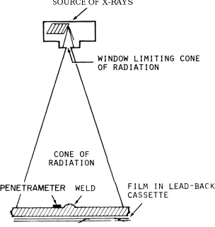
Radiographic setup. Details of penetrameters.
A scan presentation on cathode ray tube.
Straight beam inspection techniques used in scanning a tee weld.
Scanning procedure using angle beam and straight beam on a corner weld. Several uses of the IIW block.
Scanning procedures for welds not ground flush. Scanning procedures for welds ground flush. Tensile test specimens.
Guided bend test jig. Free bend test.
Transverse fillet-weld shear specimen.
LIST OF TABLES
Established voltage limits.
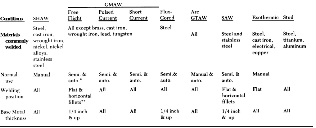
Summary of welding processes and application.
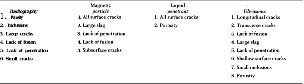
Austenitic stainless steels most commonly used for cryogenic and vacuum environment equipment. Uses of various inspection techniques.
Characteristics of radioisotope sources.
TM 5-805-7
CHAPTER 1
INTRODUCTION
1-1. Purpose and scope
This manual contains criteria and basic data for welded construction design, construction methods, and inspection procedures for Army construction. This manual covers only the following welding pro-cesses and materials commonly used for field con-struction projects: shielded metal-arc, gas metal-arc, gas tungsten-arc, flux-cored arc, submerged arc, exothermic, and arc stud welding processes. Discus-sions of physics, chemistry, and metallurgy are lim-ited to areas helpful in selecting welding processes, materials, and inspection procedures for the applica-tions listed in paragraph 1-3. For supplemental information, see the American Welding Society (AWS) Welding Handbook (available in five sections) and TM 9-237. Appendix A lists other works, codes, and specifications which are referenced in this man-ual; designers should note that there are differences among the documents’ requirements. Therefore, when this material is used, the editions which apply to a given design must be specified.
1-2. Welding applications
This manual discusses the following materials. a. Steel.
(1) Structural carbon steel welded to structural carbon steel.
(2) Structural carbon steel welded to high-strength, low-alloy steel.
(3) High-strength, low-alloy steel welded to high-strength, low-alloy steel.
(4) Carbon or high-strength, low-alloy steels for all types of piping systems.
(5) Concrete reinforcing steel. (6) Rails.
(7) Steel castings, e i t h e r c a r b o n o r h i g h -strength, low-alloy.
b. Stainless steels.
(1) Cryogenic vessels and piping materials used for storage and transport of extremely low-tempera-ture liquids.
(2) Vacuum chambers. (3) All other uses.
c. Nickel steels and nickel alloys for cryogenic vessels and piping systems.
d. Aluminum alloys for cryogenic vessels, piping systems, and other uses.
I
T M 5 - 8 0 5 - 7
CHAPTER 2
DESIGN AND INSPECTION RESPONSIBILITIES
2-1. Designer responsibilities
a. The designer must specify the base metal for t h e s t r u c t u r e , a c c o r d i n g t o d e s i g n a n d s e r v i c e requirements and provide essential metallurgical and design information in the specifications. Weld-ing process and filler metals are selected by the fabricator or, in some cases, specified by the design office to fit the material requirements; these items should be included in the specifications and indi-cated on the drawings. The joint designs must be shown on the drawings by a standard welding sym-bol or by detailed drawings of the weld joints.
b . T h e d e s i g n e r m u s t d e t e r m i n e t h e w e l d i n g requirements, and must develop or select the appro-priate welding sections of the contract for each proj-ect. These decisions are based on instructions from the using agency. The designer must develop con-tract specifications that ensure the concon-tractor knows the welding quality that must be maintained. The designer uses the following criteria to determine the required degree of control over welding quality.
(1) Strict control over welding procedures and operations is required in five cases (listed in order of increasing importance):
(a) Distress in one member could cause at least partial collapse or failure with some hazard to life and property; application of the design load may approach 10,000 cycles over many years.
(b) Some of the welds required for structural integrity are highly stressed; application of the design load may exceed 10,000 cycles over many years.
(c) Empirical design requirements compen-sate for overloads, abuse, mishandling, “acts of God,” and similar hazards; application of the design load may be on the order of 100,000 cycles.
(d) Failure of welds or components could be catastrophic, as in structures such as bridges or high--pressure gas piping systems; fatigue of materials m u s t b e c a r e f u l l y c o n s i d e r e d o r a p p l i c a t i o n o f design load is on the order of 2 million cycles.
(e) Applications require the highest quality of material and workmanship throughout, such as for nuclear, space, and ballistic applications and for sys-tems subjected to hazardous chemicals, or extreme pressures or temperatures.
(2) Less control over welding procedures and operations is needed where:
(a) Stress levels are low.
(b) WeIds are subjected only occasionally to design loads.
(c) The structure is composed of multiple components, and distress in one member will cause inconvenience rather than collapse or catastrophic failure.
c. The designer must establish the inspection pro-cedures needed to determine the weld quality. The designer must be familiar with the destructive and nondestructive methods of evaluating weld quality and must know their capabilities and limitations. Procedures to qualify inspectors must be specified.
d. The designer must establish the acceptance requirements for the welded joints, and must iden-tify the applicable military standards, specifications, and codes for meeting these requirements. When standards, codes, and other specifications are cited, the contract specification must list the paragraphs or parts of the publications which are applicable or excluded. The designer must use only the most recent codes and specifications.
e. The designer must indicate on the plans or specifications the extent of inspection and testing required for the various applications and conditions. Although the inspection and testing needed depend primarily on the design requirements, the following general guidelines should be considered.
(1) Apply value engineering — in short, do not specify unnecessary testing.
(2) Follow design criteria and codes that specify the extent of inspection and testing required relative to working stresses, joint efficiencies, or conditions of use.
(3) Inspect visually in noncritical applications or c o n d i t i o n s ; v e r y l i t t l e o t h e r t e s t i n g s h o u l d b e required.
(4) Identify the critical joints and welds and choose those to be tested. The criticality of each weld should determine the extent of nondestructive and destructive tests; these tests supplement the quality control provided by qualified procedures, qualified welders and operators, and visual inspec-tion. The weld can be critical because of high stresses, impact, vibration, temperature, safety, insurance against operational failure, hard-to-weld material, or a combination of these factors. In a mul-tistory office or warehouse building with structural
TM 5-805-7
steel framing, for example, testing would be done mainly at the highly stressed joints. In a critical pip-ing system, however, either all joints would be nondestructively tested or a uniformly applied ran-dom test procedure would be used.
(5) Determine the extent of random testing in
piping, tanks, and other elements that have uniform j o i n t s a n d d e s i g n l e v e l s . T h i s n u m b e r c a n b e expressed as a percentage of all welds in the system, coupled with a finite test increment. However, the extent of random testing in large steel structures with a variety of welds and widely varying design stresses should not be expressed this way. The designer is responsible for specifying the appropri-ate tests for critical and noncritical welds. To insure clarity in bidding and inspection documents, the location, numbers, and minimum increment lengths of the random tests should be clearly outlined.
f. The designer must indicate in the specification what to do when welds fail to meet acceptance requirements.
g. The designer must design the weld so that the operator can reach the weld joint easily. If the joint is located so that the welder cannot observe the welding operation easily or position the welding gun or electrode properly, a poor weld may result. In such cases, it may be hard or impossible to repair any weld defects.
(1) The dimensions and shape of the joint sur-faces should allow the weld metal to penetrate the joint fully. If pieces of different thicknesses are to be joined, the edge of the thicker piece should be tapered to the thickness of the thinner piece. The tapered transitions must conform to the require-ments of the following publications, as applicable: AWS D1.1; the American Society of Mechanical Engineers (ASME) Boiler and Pressure Vessel Code, Section III or Section VIII; or the American National Standards Institute (ANSI) Standard B 31.1.
(2) Good joint design practices for vessels are shown in section VIII of the ASME Boiler and Pres-sure Vessel Code; for piping in appendix D of ANSI B31.1; and for structural work in the American Insti-tute of Stee] Construction’s (AISC) Manual of Steel
Construction and AWS Dl.1.
(3) In some welding operations, some type of weld joint backing is used to support the molten weld metal and prevent excessive penetration. Back-ing strips, when used, must be of material similar to the base metals which are penetrated by the weld metal. Nonconsumable” ‘backing rings in piping
sys-tems should not essary. Instead,
be permitted unless absolutely nec-penetration can be controlled by
altering the joint design (increasing decreasing the root opening) or by ble insert rings.
(4) If the joint is welded from
the root face or using
consuma-both sides, the reverse side of the root pass (the side opposite that o n w h i c h t h e w e l d w a s d e p o s i t e d ) s h o u l d b e chipped, ground, or gouged out to sound metal before any welding is done from the second side. This operation will prevent lack of fusion at the root of the joint. The reverse side of single “V” weld joints may also be ground out and rewelded to improve the contour. Complete penetration groove welds must be welded from both sides unless a proper backup plate is used.
h. The designer must decide which welds are to be peened and which are not and indicate them on the drawings. Peening is the mechanical working of metals by hammer blows. This technique is useful for reducing distortion and residual stresses caused by shrinkage of the weld metal as it cools. However, the technique can be harmful if extreme care is not used. Since it can cause cracking, overlapping, or other defects, peening is not permitted on surface passes of the weld joints. Intermediate passes may be peened only with the contracting officer’s mission. Peening of stainless steel welds is not per-mitted because it causes hardening of the weld m e t a l . C a r e s h o u l d b e t a k e n t o p r e v e n t p e e n i n g when slag is removed from the surface pass with chipping hammers.
i. The designer must determine if the shape of the weld surface and its height above the base metal ( r e i n f o r c e m e n t ) a r e i m p o r t a n t a n d i n d i c a t e t h e shape on the drawings. An abrupt change in contour between the weld surface and the base metal may result in stress concentrations high enough to cause failure under service loadings. Therefore, the weld surface should blend smoothly into the surface of the base metal. If necessary, the edges of the weld should be ground to achieve a smooth blend of surfaces.
(1) Undercut at the edge of the weld can be repaired by grinding if the depth of undercut does not exceed 1/1 6 inch. If undercut is deeper than 1/16 inch, it should be repaired by adding weld metal to this area and then grinding the surface to a smooth, even contour.
(2) Grinding also should be used to remove overlap at the weld edges and any abrupt ridges or valleys in the weld surface.
TM 5-805-7
2-2. Contractor responsibilities
a. The contractor must develop a qualified weld-.
ing procedure, provide qualified welders and weld-ing operators, and produce satisfactory weldment.
(1) The construction drawings and specifica-tions ordinarily indicate the location of the weld joints and the type of joint required, but the con-tractor must handle the details of producing the weld — for example, the equipment used, number of passes, choice of electrode, and welding process. T h e r e f o r e , t h e c o n t r a c t o r m u s t u n d e r s t a n d t h e objective of the plans and, if necessary, seek guid-ance from the contracting officer and the welding engineer or metallurgist assigned to the project. Those concerned should meet to discuss the status of the welding program as work progresses.
(2) All welding procedures used for any of the, applications covered by this manual and all welders and welding operators assigned to these construc-tion operaconstruc-tions must be qualified before producconstruc-tion welding is begun. The contractor must conduct all qualification, testing and maintain records showing the testing procedures used and the results of these tests. These records must always be available to the i n s p e c t o r a n d t h e c o n t r a c t i n g o f f i c e r o r h i s representative.
b. The contractor must make sure the welding equiprnent is serviced and maintained properly to produce the required current output, voltage con-trol, and filler wire feed rate for automatic and semi-automatic processes. Storage and handling of flux and coated electrodes must also be done properly.
(1) Flux must be kept free of dirt, mill scale, and other foreign material. Flux fused during previous welding operations should not be reused. If there is no moisture in the flux or on the work during weld-ing, the quality of submerged-arc weld metal is com-p a r a b l e t o t h a t o b t a i n e d w i t h l o w - h y d r o g e n electrodes. Packaged flux must be stored in a warm, dry room. Loose flux stored in open containers should be subject to the same drying conditions as low-hydrogen electrodes.
(2) Excessive moisture in the electrode coatings releases hydrogen during welding, and therefore adversely affects the quality of the weld. Since this moisture may be absorbed from the atmosphere, packaged electrodes should be stored in a dry, warm room, and loose electrodes should be stored in dry-ing bins or a holddry-ing oven kept at the manufacturer’s recommended temperature.
(a) With low-hydrogen electrodes, the coat-ings have few hydrogen-producing constituents. Special care is taken in manufacturing and packaging these electrodes to maintain a low content of free and combined moisture. If these electrodes absorb
much moisture from the atmosphere, they no longer function as low-hydrogen electrodes. The rate of moisture absorption depends on the coating compo-sition and the relative humidity.
(b) The electrode manufacturer should be asked for recommendations about bake time, hold-i n g o v e n t e m p e r a t u r e , and maximum allowable exposure time for the particular electrode type, quality of weld required, and relative humidity. If this information is unavailable, a general rule is to limit atmospheric exposure to 4 hours for electrodes removed from the bake oven, from holding ovens, or from hermetically sealed metal containers. In criti-cal welding applications or when the relative humid-ity is 75 percent or higher, the exposure time may have to be reduced to as little as 1/2 hour. Elec-trodes which have been wet must not be used.
c. The contractor must ensure tack welding and jigging is done properly. Parts to be welded must be held in position before, during, and after welding to keep them correctly aligned and to minimize distor-tion caused by shrinkage of the weld metal as it cools. To do this, tack welding is frequently used either alone or as a supplement to various jigs, fix-tures, and clamps. Tack welds, which are subject to cracking if they are too small, can be a source of defects when subsequent welds are made. There-fore, tack welds should always be inspected and, if cracked, ground out before subsequent welding. Sound tack welds should be ground to a smooth con-tour that blends evenly into the base metal. This will ease complete melting of the tack weld into the sub-sequent weld. Before welding is begun, the pieces should be aligned so that afterward the abutting edges of the parts are within the offset tolerances specified in the contract.
d. The contractor must take precautions against adverse weather conditions.
(1) Welding should not be done if the surfaces are wet or covered with snow, ice, or frost. Local preheating of the joint area can be used to dry the joint surfaces. If rain or snow is falling, the joint will have to be sheltered so that the area will stay dry during welding.
(2) Welding will not be done in windy or drafty locations unless curtains or protective screens are used. Most arc welding processes incorporate a shield of gas or vaporized electrode coating to pro-tect the arc and molten weld metal from the air. If the welding is done in a windy or drafty location, this shield can be blown away, and an unsatisfactory weld will result.
(3) Welding should not be done if the ture at the weld site is below 00 F. If the tempera-ture is between O and 32°F, the joint area should be
TM 5-805-7
preheated to 70o
F or higher for welding and kept at this temperature throughout the welding operation. preheating of structural steel must conform to AWS D1.1.
e. The contractor must insure proper repair weld-ing. Defective welds must be repaired by removing the defects from the weld joint and rewelding the joints. Defects may be removed mechanically by grinding, chipping, or machining, or by arc or flame g o u g i n g . A c o m b i n a t i o n o f m e t h o d s i s o f t e n required. For example, if the defects are removed by flame or arc gouging, the cut surface may need to be cleaned mechanically and smoothed before the repair weld is made.
(1) Flame- or arc-cut surfaces of stainless steel and nickel steel have a heavy scale or oxide coating that must be removed before welding to keep it from affecting the quality of the repair weld. Also, heat from the gouging operation can affect strength by causing metallurgical changes in the weld metal adjacent to the cut surfaces. Therefore, an addi-tional 1/8 inch of metal should be mechanically removed from these cut surfaces.
(2) Defects in aluminum alloys must be removed only by mechanical means.
(3) Extra care must be used when removing cracks from welds. Nondestructive inspection may not indicate the true length of the crack, which may be too narrow to be detected with the test method being used. So, one should remove not only the weld metal in the crack, but also some sound metal at each end of the crack. The amount removed should be twice the base metal thickness or 2 inches, whichever is less at each end of the crack. After the metal is taken out and before repairs, welds should be inspected again to insure that the full length of the crack has been removed.
(4) Repair welding must be done by a qualified welder using only qualified welding procedures. The repair work might be easier with a smaller diameter electrode or filler wire than was used to make the original weld.
f. On critical welds or when requested by inspec-tors or the contracting officer, the contractor must have a welder or welding operator apply a predeter-mined identification mark to the completed weld joint. This mark is normally made on the base metal next to the weld metal. Materials may be marked by any method acceptable to the inspector as long as it does not cause notches or sharp discontinuities that could fail under service loading. The identifying mark must remain legible until acceptance of the weld metals or the structure in which the weld is c o n t a i n e d . W h e n r e q u e s t e d , t h e w e l d e r s h o u l d
apply a mark that will remain legible for the life of the structure.
g. The contractor must set up procedures for preheating, postheating, and stress relieving. The conditions to which a weldment will be exposed dur-ing service operations determine the thermal treat-ment necessary. For a broad coverage of thermal treatment, see the AWS Welding Handbook, Volume 1, “Fundamentals of Welding.” Since preheating and post-weld heat treatment affect the physical properties of the weld, the procedures must be set up in detail by the contractor or fabricator and included in the welding procedure qualification.
(1) Preheating is the application of heat to a base metal before welding or cutting. Preheating may be used during welding to help complete the w e l d e d j o i n t . T h e n e e d f o r a n d t e m p e r a t u r e o f preheating depend on several factors, such as the chemical analysis of the material, degree of restraint of the parts being joined, physical properties at ele-vated temperatures, material thickness, and ambient temperature.
(a) Preheating may be required or recom-mended for welding performed under codes or spec-ifications such as those of AWS, ASME, or the A m e r i c a n P e t r o l e u m I n s t i t u t e ( A P I ) . H o w e v e r , preheating does not necessarily assure satisfactory completion of the welded joint, and requirements must be suited to the individual materials and applications.
(b) Preheating may vary from a temperature which is warm to the touch of the hand when weld-ing outdoors in winter, to as high as 6000 F when welding highly hardenable steels. When the ambient temperature is less than 32 “F, local preheat of the weld joint area to 700 F is recommended.
(2) Post-weld heat treatment (or postheating) is a general term covering treatments done after weld-ing to restore the properties of the base metal and to produce the desired microstructure in the base and filler metals. Post-weld heat treatment may require normalizing, full annealing, quenching and temper-ing, or solution and precipitation treatments.
T M 5 - 8 0 5 - 7
2-3. Inspection requirements
Inspection is done to meet contract quality specifi-cations and to maintain quality control on the weld-ers and welding operators. Effective inspection requires cooperation between the welder or welding operator and the inspector. Inspectors should always encourage the welders and welding operator to check their own work and to report questionable welds or welding procedures. There must also be a mutual understanding between contractor and gov-ernment supervisory personnel. Inspection costs money, but good inspection often saves more than it c o s t s b y r e d u c i n g e x p e n s i v e , t i m e – c o n s u m i n g rejects or repairs, and by detecting promptly unsat-isfactory welding procedures or poor workmanship. Most inspections are to be done by the contractors (fabricators) since they will gain or lose from the quality of the product. They can also take immediate corrective action when defective weldments are found. When contractors do their own inspections, the inspection personnel should be organizationally separate from the production personnel; inspection personnel should answer not to the project superin-tendent but to a quality control element of the orga-nization. C o n t r a c t o r s m a y e m p l o y i n d e p e n d e n t commercial inspection and testing laboratories to perform these services, especially when the contrac-tor’s production o r q u a l i t y r e q u i r e m e n t s v a r y w i d e l y . I f t h e c o n t r a c t o r h a s p r o v i d e d r e l i a b l e inspectors, the government can simply spot check to make sure the inspection methods were adequate. Government inspection can be done either by gov-ernment personnel or by an independent commer-cial inspection or testing laboratory. The choice will depend on a number of factors, such as availability of qualified personnel and equipment, length of the project, cost of inspection, location of the project, and criticality of inspection or testing requirements. When qualified government personnel are available, they should do the inspection and testing. This is desirable from the standpoints of administrative con-trol, maintenance of qualified government inspec-tion personnel, and personal interest in the quality of the product. When circumstances require work by a commercial laboratory, these inspectors act as agents for the government.
a. Contractual relations.
(1) Designers, contractors, inspectors, welders, and welding operators should cooperate. The qual-ity of the welding depends largely on the skill of the contractor’s personnel, the proper choice of materi-als, and the adequacy of the welding procedure. The contractor depends on the inspectors for decisions about whether the completed welds are acceptable.
(2) Inspectors should develop a clear under-standing of the specified requirements, interpret contract provisions consistently, and avoid either favoring the contractor or making unreasonable demands. In short, they should be absolutely fair to both the government and the contractor.
(3) Although inspectors usually make the final decision about the quality of a weld, they should not take over the role of supervisors for the contractor. Acceptability of welds should not be left to discre-tion, but be based on meeting the specified require-ments. Competent contractor supervision should be provided to see that the welding procedures are being followed and that the requests made by the inspectors are carried out. As much as possible, the inspector should ask the contractor’s supervisory personnel to regulate operations, and should not give orders directly to workmen.
(4) A thorough knowledge of the work is the best assurance of a satisfactory job and a good work-ing relationship between the government and the contractor. The inexperienced inspector may unwit-tingly penalize both contracting parties by unduly emphasizing insignificant but costly details of the work, thus imposing a needless hardship on the con-tractor with little benefit to the government. At the same time, the inspector might overlook other oper-ations that may be vitally important to the job — for example, overemphasis on the strength of the weld when appearance is most important, and vice versa.
b. Inspection force. On a large project, govern-ment inspection of welding operations is assigned to an inspection section headed by an experienced supervisor. This differs from an isolated job of weld-ing where inspection may be the responsibility of one or two individuals. On a large project where the inspection of all welding is given to a specialized team, assignments in the early stages of construction may be arranged so that inexperienced inspectors can watch the actions and decisions of experienced personnel. This procedure will help train a compe-tent team that will operate efficiently at a later stage of work. This approach is not possible, however, on small projects with only one inspector. Only exper-ienced construction personnel should be assigned in such cases.
c. Inspector’s duties. The inspector must examine in detail each phase of the welding operation to make sure the work is being done right. The inspec-tor must observe such requirements as procedure and welder qualifications, joint design and prepara-tion, alignment, electrode size and type, welding equipment, and technique. When an assignment is rotated, a new inspector must learn about the proce-dures being followed and the status of welding and
T M 5 - 8 0 5 - 7
inspection before assuming inspection responsibility.
d. Supervision. Good supervision of inspectors is important to satisfactory welding operations on a large project. Even the most experienced inspector can do little unless properly instructed in the work and given the fullest support in dealings with weld-ing personnel. The supervisor must clarify the responsibilities of each part of the organization and outline the limits of each inspector’s authority. The supervisor should tell the inspector about all deci-sions on acceptance requirements and other issues.
T M 5 - 8 0 5 - 7
CHAPTER 3
WELDING PROCESSES
3-1. General
T h i s c h a p t e r c o n t a i n s g e n e r a l r e q u i r e m e n t s f o r welding processes that may be used for the applica-tions covered in paragraph 1-2.
3-2. Processes
a. The welding processes covered by this design. manual are as follows:
(1) Shielded metal-arc (SMAW) (2) Gas metal-arc (GMAW)
(a) Free-flight transfer
(b) Pulsed-current out-of-position welding (c) Short circuiting
(3) Flux-cored arc welding (FCAW) (4) Gas tungsten-arc (GTAW) (5) Submerged-arc (SAW) (6) Exothermic (Thermit) (7) Arc stud (STUD)
b. Basically, in the electric welding processes, an arc is produced between an electrode and the work piece (base metal). The arc is formed by passing a
-c u r r e n t f r o m t h e e l e -c t r o d e t o t h e w o r k p i e -c e through a gap. The current melts the base metal and the electrode if it is a consumable type, creating a molten pool. On solidifying, the weld is formed. An alternate method employs a nonconsumable elec-trode such as a tungsten rod. In this case, the weld is formed by melting and solidifying the base metal at the joint. In some instances, additional metal is required and is added to the molten pool from a filler rod.
c. Electrodes which become the deposited weld metal are available in various diameters and lengths. In welding, the molten pool must be protected from the ambient atmosphere to prevent contamination. There are three ways to do this. Two involve a flux; in one, the flux is part of the electrode, either as a coating on the wire or as the core of a hollow wire. The second method uses a granulated flux that is a p p l i e d s e p a r a t e l y b e f o r e w e l d i n g . T h e t h i r d method involves a gas such as helium, argon, or car-bon dioxide. In addition to shielding, the flux may
TM 5-805-7
function as a deoxidizer to purify the deposited metal or to form slag to protect the weld metal from oxidation. The flux may contain ionizing elements to provide smoother operation, alloying elements to p r o v i d e h i g h e r s t r e n g t h , a n d i r o n p o w d e r t o increase production rates. The selection of elec-trodes for a specific job can be based on the follow-ing eight factors:
(1) Base metal strength properties (2) Base metal composition (3) Welding position (4) Welding current (5) Joint design and fit-up
(6) Thickness and shape of base metal (7) Service conditions and/or specifications (8) Production efficiency and job conditions The AWS publishes a group of specifications for fil-ler metals (electrodes) and recommends the welding process for which they are to be used. In addition, AWS D1.1 describes the welding procedures to be used with the various welding processes.
d. Welding material — electrodes, welding wire, and fluxes — must produce satisfactory welds when used by a qualified welder or welding operator using qualified welding procedures. Welding materials must comply with the applicable requirements of AWS D1.1, ASME Boiler and Pressure Vessel Code, Section II, or other requirements in the contract specifications.
3-3. Shielded metal-arc (SMAW)
T h i s i s t h e m o s t w i d e l y u s e d m e t h o d f o r g e n e r a l –
welding application; it may also be referred to as metallic-arc, manual metal-arc, or stick-electrode welding.
a. Advantages. The SMAW process can be used for welding most structural and alloy steels. These include low-carbon or mild steels; low-alloy, heat-treatable steels; and high-alloy steels such as stain-less steels. SMAW is used for joining common nickel alloys and can be used for copper and aluminum alloys. This welding process can be used in all posi-tions — flat, vertical, horizontal, or overhead — and requires only the simplest equipment. Thus, SMAW lends itself very well to field work (fig 3-l).
b. Disadvantages. SMAW is clearly inferior to GMAW if one compares the cost of the time and materials needed to deposit the weld metal. SMAW deposits the weld more slowly than does GMAW. In addition, slag removal, unused electrode stubs, and spatter add a lot to the cost of SMAW; the latter two items account for about 44 percent of the consumed electrodes. Another potential cost is the entrapment of slag in the form of inclusions which may have to be removed.
T M 5 - 8 0 5 - 7
“
T M 5 - 8 0 5 - 7
T M 5 - 8 0 5 - 7
28
-26
24
22
20
8
6
4
2
TM 5-505-7
T M 5 - 8 0 5 - 7
struck against the base metal and withdrawn to cre-ate a gap. The molten portion of the electrode fuses into the molten pool of the base metal, producing the weld (fig 3-2). Since SMAW is a manual process, the operator is primarily responsible for quality of the weld. Most of the melted electrode metal is transferred to the work piece; the rest is thrown free of the weld as spatter or is vaporized. Of that vaporized, some escapes into the surrounding air, becomes oxidized, and appears as smoke or fumes. The electrode used for SMAW has a special covering which serves several purposes. Part of the covering c o n t a i n s g a s - p r o d u c i n g c o m p o u n d s t h a t , w h e n heated, produce a gaseous envelope around the arc that displaces air and stabilizes the arc. The covering also protects the molten weld metal from contamina-tion by air. Without this stabilizacontamina-tion, the arc would be erratic, would often short out, and generally would be hard to control. Different gas-producing compounds are used in the coating, depending on the type of current — alternating (AC) or direct
(DC). The covering also contains slag-forming mate-rials that mix with the molten weld metal and pick up impurities from the weld metal. This cleaning action improves the quality of the weld. Most of the electrode coating does not become vaporized but instead is melted by the arc heat and forms a molten slag cover over the top of the weld bead. This mol-ten slag cover helps to control the shape of the weld bead. It also helps to hold the molten weld metal in place during out-of-position welding (i.e., welding in the overhead, vertical, or horizontal positions). Chapters 4 and 5 discuss the numbering system, color coding, flux composition, and other data con-cerning welding electrodes. In shielded metal-arc welding, five distinct forces are responsible for the transfer of molten filler metal and molten slag to the base metal.
(1) Gravity. Gravity is the principal force which. accounts for the transfer of filler metal in flat posi-tion welding. In other posiposi-tions, the surface tension is unable to retain much molten metal and slag in the
crater. Therefore, smaller electrodes must be used to avoid excessive loss of weld metal and slag.
(2) Gas expansion. Gases are produced by the burning and volatilization of the electrode coating and are expanded by the heat of the boiling elec-trode tip. The coating extending beyond the metal tip of the electrode controls the direction of the rapid gas expansion and directs the molten metal globule into the weld metal pool formed in the base metal.
(3) Electromagnetic forces. The electrode tip is an electrical conductor, as is the molten metal glob-ule at the tip. Therefore, the globglob-ule is affected by magnetic forces acting at 90 degrees to the direction of the current flow. These forces produce a pinching effect on the metal globules and speed up the sepa-ration of the molten metal from the end of the elec-trode. This is particularly helpful in transferring metal in horizontal, vertical, and overhead position welding.
(4) Electrical forces. The force produced by the voltage across the arc pulls the small, pinched-off globule of metal, regardless of the position of weld-ing. This force is especially helpful when one uses
direct-current, straight-polarity, mineral-coated electrodes, which do not produce large volumes of gas.
(5) Surface tension. The force which keeps the filler metal and slag globules in contact with molten base or weld metal in the crater is known as surface tension. It helps to retain the molten metal in hori-zontal, vertical, and overhead welding, and to deter-mine the shape of weld contours.
d . E q u i p m e n t , T h e e q u i p m e n t n e e d e d f o r shielded metal-arc welding is much less complex than that needed for other arc welding processes. Manual welding equipment includes a power source (transformer, DC generator, AC generator, or DC rectifier), electrode holder, cables, connectors, chipping hammer, wire brush, and electrodes.
T M 5 - 8 0 5 - 7
WIRE DRIVE MAY BE LOCATED IN WELDING GUN HANDLE OR AT WIRE REEL
TM 5-805-7
“Note all electrodes 1/8-inch diameter except E8018, which is 5/32-inch diameter.
3-4. Gas metal-arc (GMAW)
GMAW is a process in which an electric arc is estab-lished between a solid, consumable, spool-fed elec-trode and the work piece. The arc, elecelec-trode tip, and molten weld metal are shielded from the atmos-phere by a gas. This welding process has been com-monly called metal-inert-gas welding (MIG). There are two main types of metal transfer: free flight and short circuiting. Free-flight transfer can be pro-jected or spray, repelled, and gravitational or globu-lar. These three forms of free-flight transfer are basically for flat position welding (fig 3-10). A modi-fication of free-flight transfer is pulsed current, which can be used in all welding positions. The short-circuiting transfer, sometimes called short-arc, uses a low current and is for welding thin materials in all positions. All the GMAW processes use basi-cally the same equipment, as shown in figure 3-11. AWS D1.1 describes electrodes, shielding gas, and w e l d i n g p r o c e d u r e s f o r G M A W u s i n g s i n g l e electrodes.
a. Free-flight transfer gas metal-arc welding. (1) Advantages. The major advantage of free-flight transfer welding is that high-quality welds can b e p r o d u c e d m u c h f a s t e r t h a n w i t h S M A W o r GTAW. Since a flux is not used, there is no chance for the entrapment of slag in the weld metal. The gas shield protects the arc so that there is very little loss of alloying elements as the metal transfers across the arc. Only minor weld spatter is produced, and this is easily removed. The free-flight process is versatile and can be successfully used with a wide variety of metals and alloys: aluminum, copper, magnesium, nickel, and many of their alloys, as well as iron and most of its alloys. The process can be operated in several ways, including semi- and fully automatic. GMAW is widely used by many industries for weld-i n g a b r o a d v a r weld-i e t y o f m a t e r weld-i a l s , p a r t s , a n d structures.
(2) Disadvantages. The major disadvantage of free-flight transfer is that it cannot be used in verti-cal or overhead welding due to the high heat input and the fluidity of the weld puddle. In addition, the
equipment is complex compared with that for the SMAW process.
( 3 ) P r o c e s s p r i n c i p l e s . I n f r e e - f l i g h t t r a n s f e r , –
the liquid drops that form at the tip of the consuma-ble electrode are detached and travel freely across the space between the electrode and work piece before plunging into the weld pool (fig 3-l0). When the transfer is gravitational, the drops are detached by gravity alone and fall slowly through the arc col-umn, In the projected type of transfer, other forces give the drop an initial acceleration and project it independently of gravity toward the weld pool, Dur-ing repelled transfer, forces act on the liquid drop and give it an initial velocity directly away from the weld pool. The gravitational and projected modes of free-flight metal transfer may occur in the gas metal-arc welding of steel, nickel alloys, or aluminum alloys using a direct-current, electrode-positive (reverse polarity) arc and properly selected types of shielding gases. At low currents, wires of these alloys melt slowly. A large spherical drop forms at the tip and is detached when the force due to gravity exceeds that of surface tension. As the current increases, the electromagnetic force becomes signif-icant and the total separating force increases. The rate at which drops are formed and detached also increases. At a certain current, a change occurs in the character of the arc and metal transfer. The arc column, previously bell-shaped or spherical and having relatively low brightness, becomes narrower and more conical and has a bright central core. The droplets that form at the wire tip become elongated due to magnetic pressure and are detached at a much higher rate. When carbon dioxide is used as the shielding gas, the type of metal transfer is much different. At low and medium reversed-polarity cur-rents, the drop appears to be repelled from the work electrode and is eventually detached while moving away from the work piece and weld pool, This causes an excessive amount of spatter. At higher cur-rents, the transfer is less irregular because other forces, primarily electrical, overcome the repelling forces. Direct current reversed-polarity is recom-mended for the GMAW process. Straight polarity and alternating current can be used, but require pre-cautions such as a special coating on the electrode wire or special shield gas mixtures.
T M 5 - 8 0 5 - 7
TM 5-805-7
T M 5 - 8 0 5 - 7
manual and automatic welding guns are available. The manual welding guns have many designs. All the manual guns have a nozzle for directing the shield-ing gas around the arc and over the weld puddle. The filler wire passes through a copper contact tube in the gun, where it picks up the welding current. Some manual welding guns contain the wire-driving mechanism within the gun itself. other guns require that the wire-feeding mechanism be located at the spool of wire, which is some distance from the gun. In this case, the wire is driven through a flexible conduit to the welding gun. Another manual gun design combines feed mechanisms within the gun and at the wire supply itself’. Argon is the shielding gas used most often. Small amounts of oxygen (2 to 5 percent) frequently are added to the shielding gas when steel is welded. This stabilizes the arc and promotes a better wetting action, producing a more uniform weld bead and reducing undercut. Carbon dioxide is also used as a shielding gas because it is cheaper than argon and argon-oxygen mixtures.
Electrodes designed to be used with carbon dioxide shielding gas require extra deoxidizers in their for-mulation because in the heat of the arc, the carbon dioxide dissociates to carbon monoxide and oxygen, which can cause oxidation of the weld metal.
(5) Welding parameters. Figures 3-12 through 3-18 show the relationship between the voltage and current levels, and the type of transfer across the arcs.
b. Pulsed-current GMAW process.
(1) Advantages. This process is useful when low heat input is required — when one is working with thin materials or doing out-of-position welding, for example. In the lower heat-input range, pulsed cur-rent has the advantage of the continous projected spray-transfer process. High-quality welds can be produced in mild and low-alloy steels. In the weld-ing of aluminum, larger diameter wires can be used; welds with less porosity are produced because there is less hydrogen and oxygen pickup on the wire surface.
T M 5 - 8 0 5 - 7
(2) Disadvantages. The major disadvantage of this process is the complex power supply required in addition to the GMAW wire feeder and welding torch.
(3) Process principles. Pulsed-current GMAW is a modification of the process used to obtain spray-type transfer with average current levels in the glob-ular-transfer range. This process provides a higher ratio of heat input to metal deposition rate than the s h o r t - c i r c u i t i n g p r o c e s s . P u l s e d - c u r r e n t G M A W operates at heat inputs between those used for spray transfer and short-circuiting transfer, with some overlap in the ranges. In this process, the current is pulsed back and forth between projected-transfer and gravitational-transfer ranges by electronically switching the current level back and forth between them. Figure 3-19 shows the current output-wave form and metal-transfer sequence. Pulsed-current welding is also known by the trade name “pulsed-arc. ”
(4) Equipment. The power sources for pulsed current combine a three-phase, full-wave trans-former-rectifier power supply, and a single-phase, half-wave pulse unit. These units are connected in parallel, but are electronically switched in operation to give the output waveform shown in figure 3-19.
I 2 34
Standard GMAW in this process.
wire feeder and torches are used
c. Short-circuiting transfer GMAW welding. (1) Advantages. The short-circuiting process is widely used for quickly welding thin materials (up to 1/4 inch) in all positions; it causes little distortion and few metallurgical defects. This process is used on carbon and low-alloy steels, and less often on stainless steel and aluminum; it is also used for out-of-position welding of thicker materials.
(2) Disadvantages. Generally, welds made with the short-circuiting process are of slightly poorer quality than those produced by the spray-transfer method. This may not cause trouble if high-quality welds are not required.
(3) Process principles. The short-circuiting transfer variation of the GMAW process is generally similar to spray-transfer welding. The main differ-ence is the way the molten metal is transferred from the end of the electrode wire to the weld puddle. In spray-transfer welding, d r o p l e t s a r e t r a n s f e r r e d through the arc. With the short-circuiting process, metal transfer occurs during repetitive short circuits caused when the molten metal from the electrode contacts the weld puddle. The welding current is well below the transition level required for spray
T M 5 - 8 0 5 - 7
transfer. As the end of the filler wire melts, it forms a ball (fig 3-20). This becomes larger until it touches the weld puddle, extinguishing the arc and creating a short circuit. The arc length is deliberately kept short so that the metal ball touches the puddle before it separates from the end of the filler wire. When the short circuit occurs, the welding current increases rapidly, causing the drop of molten metal to be “pinched” from the end of the filler wire. The arc is reinitiated and the process repeated. The short-circuiting action is very rapid; as many as 200 short circuits per second may occur. This process is also known as “short arc, ” dip-transfer, or fine wire welding,
(4) Equipment. Short-circuiting transfer weld-ing uses the same constant voltage equipment as does spray transfer. The power source must have a device that inserts a variable but controlled amount of inductance into the electrical circuit. This induc-tance controls the rate of current increase when the short circuit occurs and permits the arc to restart without weld-metal spatter.
(a) Short-circuiting welding requires a smaller diameter filler wire (0.030-inch diameter, for exam-p l e ) t h a n i s g e n e r a l l y u s e d f o r s exam-p r a y - t r a n s f e r welding.
(b) The shielding gas used for short-circuiting welding depends on the metal being welded. Argon, helium, or mixtures of these are used for welding aluminum. Carbon dioxide, a mixture of carbon dioxide and argon, or argon with a small oxygen addition is used when welding mild or low-alloy steel. For stainless steel, argon with oxygen or car-bon dioxide additions is used.
3-5. Flux-cored arc welding (FCAW)
Flux-cored, tubular-electrode welding has evolved from the GMAW process to improve arc action, metal transfer, weld-metal properties, and weld appearance.
a. Advantages. The major advantages of flux-cored welding are reduced cost and higher deposition rates than either SMAW or solid wire GMAW. The cost is less for flux-cored electrodes because the alloying agents are in the flux, not in the steel filler wire as they are with solid electrodes. Flex-cored welding is ideal where bead appearance is important and no machining of the weld is required. Flex-cored welding without carbon dioxide shielding can be used for most mild steel construction applica-tions, The resulting welds have higher strength but less ductility than those for which carbon dioxide shielding is used. There is less porosity and greater penetration of the weld with carbon dioxide shield-ing, The flux-cored process has increased tolerances for scale and dirt; there is less weld spatter than with solid-wire GMAW.
b. Disadvantages. Most low-alloy or mild-steel electrodes of the flux-cored type are more sensitive to changes in welding conditions than are SMAW electrodes. This sensitivity, called voltage tolerance, can be decreased if a shielding gas is used, or if the slag-forming components of the core material are increased. A constant-potential power source and constant-speed electrode feeder are needed to main-tain a constant arc voltage.
c. Process principles. The flux-core welding wire, or electrode, is a hollow tube filled with a mixture of deoxidizers, fluxing agents, metal powders, and ferro alloys, as shown in figure 3-21. The closure seam, which appears as a fine line, is the only visible
I 2 3 4 5 6
TM 5-805-7
difference between flux-cored wires and solid cold-drawn wire. Flux-cored electrode welding can be done in two ways: carbon dioxide gas can be used with the flux to provide additional shielding, or the flux core alone can provide all the shielding gas and slagging materials. The carbon dioxide gas shield produces a deeply penetrating arc and usually pro-vides better weld than is possible without an exter-nal gas shield.
d. Equipment. The equipment and controls for the flux-core process are similar to, and sometimes the same as, those used in the stray-transfer method. The unit consists of a constant-speed wire-drive sys-tem, water- or air-cooled welding torch, and a con-stant-potential DC unit with a 100-percent duty cycle.
3-6. Gas tungsten-arc (GTAW)
The GTAW process uses a nonconsumable electrode and an inert shielding gas. This process is also known as TIG (tungsten inert gas) and by the trade name “Heliarc.” GTAW is similar to other arc-welding processes in that the heat is generated by an arc between a nonconsumable electrode and the work piece, but the equipment and the electrode type d i s t i n g u i s h G T A W f r o m t h e o t h e r a r c w e l d i n g processes.
a. Advantages. The GTAW process is the most
p o p u l a r m e t h o d f o r w e l d i n g a l u m i n u m , s t a i n l e s s _ steel, and nickel base alloys. It produces top quality
welds in almost all metals and alloys used in indus-try. The process provides more precise control of t h e w e l d t h a n a n y o t h e r a r c w e l d i n g m e t h o d because the arc heat and filler metal are indepen-dently controlled, Visibility is excellent because no smoke or fumes are produced during welding; there is no slag or splatter that must be cleaned between passes or on a completed weld, GTAW is usually considered one of the most versatile processes because it produces the highest quality welds in any position or configuration, The final major advantage is reduced distortion in the weld joint because of the concentrated heat source. This is one of the best precautions that can be taken to prevent weld crack-ing or locked-up stresses.
b. Disadvantages. The GTAW process is expensive because the arc travel speed and weld metal deposi-tion rates are lower than with some other methods. In addition, it is less advantageous to use GTAW on heavy, thick materials.
c. Process principles. In the GTAW process, the tungsten alloy electrode is mounted in a special electrode holder designed to furnish a flow of inert gas around the electrode and the arc. The arc is
T M 5 - 8 0 5 - 7
struck between the base metal and the electrode by one of two methods. In the first, called a scratch start, the operator actually touches the work piece with the tungsten and withdraws slightly. The sec-ond method uses high-frequency discharge from the electrode to the work piece to establish the arc. This is better for welds that have to be very clean; a scratch start could leave particles of tungsten in the weld, causing brittle spots. After the arc is started, the filler metal, if required, is fed into the weld pool near the arc, as shown in figure 3-22. The molten weld metal, the adjacent base metal, and the elec-trodes are protected by a flowing gaseous envelope of inert gas: generally argon, helium, or a mixture of the two. Most GTAW is done manually, but for pro-duction or assembly type welds such as long butt welds, the system can be entirely automated. AC is used generally for aluminum and magnesium, while DC straight polarity is used for all other metals.
d. Equipment. The equipment includes an electri-cal power source, electrode holder (torch), tungsten or tungsten alloy electrodes, gas flow regulating equipment, and usually a remote rheostat for off-on switching and current control (fig 3-22).
(1) There are AC and DC power units with built-in high frequency generators designed specifi-cally for GTAW. These automatispecifi-cally control gas and water flow when welding begins and ends. How-ever, power supplies without these controls can also be used.
(2) If the electrode holder (torch) is water-cooled, a supply of cooling water is needed. Elec-trode holders are made so that elecElec-trodes and gas nozzles can be readily changed, either for different sizes or for replacement.
(3) Mechanized GTAW equipment may include electronic devices for checking and adjusting the welding torch level, equipment for work handling, provisions for initiating the arc and controlling gas and water flow, and filler metal feed mechanisms.
3-7. Submerged arc (SAW)
In the SAW process, the arc is not visible, but is submerged under a layer of granulated flux (fig 3-23). This process can be used with either a single electrode wire or many. AWS D1.1 describes the procedure, equipment, electrodes, and flux used with SAW.
a. Advantages. SAW is an efficient process that can be used on nearly all ferrous metals. Welds of very good quality are produced in a wide range of metals thicker than 1/1 6 inch. Carbon, alloy, or stainless steels up to l/2-inch thick are welded in one pass, while thicker materials require more passes. Weld metal deposition rates, arc travel
speeds, and weld completion rates are better than those for other processes. There is no visible arc and no weld spatter, and the deep penetrating effect of concentrated heat allows narrow welding grooves. Thus, it takes less filler metal to make a joint with S A W t h a n w i t h o t h e r w e l d i n g p r o c e s s e s , T h e unfused flux can be recovered and recycled when the welding is finished.
b. Disadvantages. The basic limitation of SAW is that it can only be used in the flat position and for horizontal fillet welds. Welds can be made in the horizontal position, but since the granular flux needed to shield the weld metal must be in place in front of the electrode, complicated dams and sup-ports may be required to contain the flux. The equipment used in this process can be hand-held, but is usually mechanized, making it heavy and cum-bersome and thereby limiting its use to fabrication shops. The fused flux must be removed by chipping and wire brushing.
c. Process principles. SAW takes place beneath the flux covering without sparks, spatter, smoke, or flash. The electrode and weld pool are completely covered at all times during welding. The flux makes possible these special operating conditions, which distinguish SAW from other processes. When cold, the flux does not conduct electricity; therefore, the welder must establish a conductive path for starting the arc. This can be done by scratch starting where the electrode touches the base plate or by burying some steel wool in the flux at the starting point. In the molten state, the flux becomes highly conduc-tive. Once the arc is started, the heat produced by the current causes the surrounding flux to become molten. This forms a conductive path, which is kept molten by the continued flow of welding current. The buried part of the flux is melted; the visible part remains unchanged in both appearance and proper-ties, and can be reused. All currents and polarities are used, depending on the desired penetration and bead shape, Reverse polarity provides the best bead shape and penetration, while straight polarity gives higher deposition rates but less penetration. Alter-n a t i Alter-n g c u r r e Alter-n t p r o v i d e s p e Alter-n e t r a t i o Alter-n s o m e w h e r e between the two and is preferred for multi-wire welding. The fused flux is chipped off the weld and discarded.
(1) The welding electrodes must be positioned properly. Flux is fed in front of and around the trode by a hopper. The arc is struck and the elec-trodes moved along the weld. The operator watches the ammeter and voltmeter readings to control cur-rent and voltage adjustments. A variable-speed motor controls the electrode feed; a power-operated
carriage controls the travel rate. Unused flux is fed back into the hopper.
(2) Moderately thick sections of material (up to 1 inch) with a carbon content up to 0.35 percent can be welded without precautions such as preheating and postweld heat treatment. Preheating is gener-ally needed when the carbon content is over 0.35 percent.
(3) Low-alloy steels maybe welded if the weld. area is preheated to slow the rate of cooling. This must be done to avoid cracking in the weld and heat-affected zone.
(4) When certain quenched and tempered struc-tural steels (ASTM A 514 and A 517) are welded, the heat input must be closely controlled to make sure strength and notch toughness are retained in the heat-affected zone. To keep a high level of strength and notch toughness, heat must dissipate
rapidly so that desirable microstructure form. Any-thing that delays cooling, such as preheating or high welding heat inputs, should be avoided.
d. Equipment. Both semi-automatic and automatic SAW equipment is available; the type used generally depends on the work to be done, and on economic factors. Semi-automatic equipment is better for repair welding and for welding that cannot be done automatically because of the geometry of the part. Figure 3-24 shows the equipment needed for auto-matic SAW; included are a power source, wire feed-ing system, flux feedfeed-ing system, and a weldfeed-ing torch. (1) The power supply may be DC constant cur-rent, DC constant voltage, or AC. The power supply and wire-drive mechanism must be designed to operate together so that the arc length can be con-trolled effectively. SAW generally is done at higher currents (500 to 1000 amperes) than other types of arc welding, so the power supply must have a high current rating at high duty cycles.
T M 5 - 8 0 5 - 7
(2) The electrodes used with SAW are generally bare rods or wire in coils. The choice of electrode depends on the way the alloying elements are intro-duced into the weld. One method is to use mild-steel electrodes with fluxes containing the alloy. Another method often used requires special alloy steel electrodes and neutral flux, and includes low-carbon steel, low-low-carbon alloy steel, special alloy steels, high-carbon steels, stainless steels, and non-ferrous alloys.
(3) The fluxes are granulated, fusible mineral materials of various compositions and particle sizes. The choice of flux depends on the welding proce-dure, joint configuration, and composition of the base metal to be welded. The flux may include alloying elements.
3-8. Exothermic welding
In exothermic welding, heat is generated by the chemical reaction between a combination of alumi-num and iron oxide. This mixture is placed in a hop-per above a mold which surrounds the joint, and is then ignited. A chemical reaction occurs, and the molten metal and slag drop through the hopper. Since the molten metal is heavier than the slag, it
settles to the bottom of the mold and touches the
steel joint. The molten metal melts the surface of the metal and fuses with it, forming the weld. This pro-cess, commonly referred to as “thermit welding, ” is used for joining reinforcing rods, rails, large castings
or forgings, and for repairing large structural shapes. Historically, thermit welding was largely confined to structures made of iron and steel. But recently, the substitution of a copper oxide for iron oxide has led to many applications within the electrical industry such as joining or repairing electrical connectors, cables, bus bars, and bus tubes. Thermit welding is also used for welding pipe. In this application the t h e r m i t d o e s not mix with the pipe metal, but merely furnishes the heat to melt the pipe ends, which are then butted together as they melt.
a. Advantages.
(1) The welder needs very little instruction or experience to produce good welds rapidly.
(2) Large sections may be fusion welded, and large quantities of filler metal may be deposited quickly. Thermit welding can be roughly compared to a foundry casting operation. The one difference is that the metal being poured is considerably hotter than when melted in a furnace. The completed weld
T M 5 - 8 0 5 - 7
b. Disadvantages. Molds are needed to hold the molten metal around the weld joint. For one-of-a-kind jobs, such as repairs, the molds must be con-structed individually, and a suitable wax or plastic form filler materials must be inserted in the gap to
insure proper clearance between the parts.
Preformed permanent molds are used for repetitive
jobs — welding rails or reinforcing rods, for
example.
c. Process principles. Thermit welding is based on the fundamental principle that aluminum is more
chemically active than iron. The welding process
consists of mixing the iron oxide and aluminum, both in powder form, and placing them in a hopper or crucible above a mold which surrounds the joint area. (The joint to be welded must be cleaned, prop-erly spaced, and preheated. ) An ignition powder, such as a mixture of barium peroxide and aluminum powder, is placed on top of the thermit, and a fuse is inserted into the powder. The reaction starts after
the fuse ignites the mixture; this happens at about 2000 “F. The reaction is nonexplosive and takes about 30 seconds; once the mixture starts to burn, it is self-propagating. When the reaction is complete, the molten metal has reached a temperature of a p p r o x i m a t e l y 4 5 0 0o
F, which is nearly 1 6 0 0o
F
higher than the temperature of ordinary molten steel. The metal is poured into the mold to form the weld (fig 3-25). The mold is allowed to remain in position for several hours to permit solidification and to anneal the weld. The deposited metal cools uniformly and is comparatively free from stresses. The mold is then removed and the gates and risers a r e c u t a w a y , E x c e s s w e l d c a n b e g r o u n d o r machined. Although the principal application of thermit welding has been with the aluminum and iron oxide mixture on steel structures, other metals or their oxides may be included in the thermit mix-ture. Chromium, nickel, manganese, tungsten, tita-nium, molybdenum, and cobalt can be used. These
T M 5 - 8 0 5 - 7
elements alloy with iron and are used when higher strength, ductility, or hardness is required. They also permit control of the temperature and time of the reaction. Cast iron can be welded with a special thermit mixture.
d. Equipment. Thermit welding kits are available. They consist of a permanent mold, prepackaged thermit charges, consumable tapping discs, charges of ignition powder, and fuses. An individually con-structed mold requires wax or foam filler, sand mold (a special mixture of silica sand and plastic clay), and gates, risers, pouring gates, and a slag basin (fig 3-25).
3-9. Arc-stud welding
Arc-stud welding is an arc welding process in which an electric arc is struck between a metal stud and another piece of metal. When the surfaces to be
j o i n t e d a r e p r o p e r l y h e a t e d , t h e y a r e b r o u g h t together under pressure. A ceramic ferrule
sur-rounding the stud can provide partial shielding. The process is generally referred to as “stud welding. ”
A W S D 1 . 1 d e s c r i b e s s t u d w e l d i n g p r o c e d u r e s , equipment, w o r k m a n s h i p , q u a l i t y c o n t r o l , a n d inspection requirements.
a. Advantages. Arc-stud welding has many advan-tages and uses. With this process, there is no need to drill or punch holes, nor to fasten an object mechan-ically to a main structure with bolts, rivets, or screws. Arc-stud welding is widely accepted by all the metal-working industries. Since virtually every phase of the operation is automatic, no previous welding experience is necessary. Inexperienced operators can be trained quickly, and once the equipment is set for a particular job, high-quality welds are quickly and easily made. The welding gun
TM 5-805-7