Real-Time Collision Detection and Response
Using Sphere-Trees
O'Sullivan, Carol and Dingliana, John
1Image Synthesis Group, Trinity College Dublin.
1
{Carol.Sullivan | [email protected]}
Abstract
In this paper we address the problem of collision detection and response in real-time animation systems. We describe an approach, which approximates objects using sphere-trees, and uses an interruptible detection algorithm to approximately test for collisions between them, trading accuracy for speed. A model of human visual perception of collisions is used to decide which collisions deserve more processing time. Collision processing is then scheduled to minimise the perceived inaccuracy within the time available. In response to such approximate collisions, a new adaptive collision response algorithm is presented, which also uses sphere-trees to approximate the appropriate response for colliding objects.
1 Introduction
Many interactive animation systems, such as games or simulations, require large numbers of virtual entities which are moving and interacting with each other, and/or with one or more users. In these applications, we cannot predict in advance how the user or the entities will behave, so we must create the animation as we watch it, i.e. in real-time. This means that the image must be re-drawn at least 10 times per second, although for true real-time performance the generation of up to 60 frames per second (f.p.s) may be required. Hence, there will be 100 milliseconds available, at the most, to update all entities in the simulation, and then render the new scene.
A possible scenario could be a game where a user must navigate his/her way through a rockfall without being hit. As multiple rocks are falling, they hit off each other and the edges of a ravine, either bouncing or breaking into smaller rocks. In order to achieve this effect, collisions between the rocks and with the ravine edges must be detected. Many other application areas exist: Large-scale Virtual Reality (VR) systems with thousands of moving entities; Crowd simulations; Flocks of birds or other organisms; Educational simulations with chemical molecules or blood cells. Anything, in fact, where you have large numbers of entities moving around a virtual world in real-time.
There are many bottlenecks in such systems. Depending on the level of realism required, rendering and motion synthesis algorithms require a large amount of processing power. In multi-user systems, network lag is a major issue. Some solutions to these problems could be to
increase the computational power, add hardware accelerators, and develop parallel algorithms that may be implemented on multiple processors. However, using such approaches, the problem is postponed rather than eliminated, and such computational power will not be available to a wide range of users. An additional challenge is maintaining a constant frame rate. The time taken to render a given scene is dependent on the current level of complexity. Some frames may require only one object to be rendered, whereas a sudden change of view may cause many more interacting objects to be visible in subsequent frames. Obviously, the latter set of frames will take longer to process than the former, regardless of the computational power available. Hence, increasing computational power alone is not the solution. It may sometimes be necessary to trade realism and accuracy for speed, and aim to achieve optimal realism in the time available, thus maintaining a high and constant frame-rate.
In this paper, we address the problem of collision handling, and demonstrate how interactions between objects may be handled in real-time, reducing the variability of the frame-rate by interrupting processing when required. Artefacts will inevitably be introduced due to the reduced accuracy of our calculations, but we reduce the visual impact of these inaccuracies by using perceptual information. In Section 2 we introduce the problems of collision detection and response, and review current work. In Section 3 we describe the collision handling algorithms we have developed, and an application which uses them. Section 4 presents conclusions and plans for future work.
2 Background
In many interactive real-time animation systems, such as those described above, the entities often need to be viewed not as geometric shapes devoid of physical properties, but as real entities having properties such as mass, moment of inertia, elasticity, and friction. Their motions are constrained not only by their own physical properties, but also by collisions with other objects. If two solid objects collide in the real world, they bounce off each other, or break into pieces, and deform if their surfaces are non-rigid. In a computer world, there is nothing to stop geometrically modelled objects from simply floating through each other like ghosts! A
when they come into contact, i.e. they should not interpenetrate, and their behaviour subsequent to collision should be compatible with their physical properties. This involves two very distinct phases: Collision Detection, and Collision Response. Detection is a problem of kinematics, while response is a problem of dynamics.
2.1 Collision Detection
Traditional collision detection algorithms have required a large amount of geometrical intersection tests, checking if any of the polygons used to model the surface of one entity touch or penetrate any polygon on the other entity. To improve the efficiency of such algorithms, hierarchical representations of entities were generated, to localise the areas where the actual collision occurred. Such representations approximate the topology of an object at different levels of detail. These include Sphere-Trees [Palmer and Grimsdale 1995][Hubbard 1995,1996][Quinlan 1994], OBB-trees (Oriented Bounding Boxes) [Gottschalk et al. 1995], ShellTrees [Krishnan et al. 1998], and hierarchies of k-DOPs (Discrete Orientation Polytopes)[Klosowski et al. 1997]. Most of these algorithms are actually hybrid algorithms, involving two or more phases of detection at varying degrees of accuracy. The broad phase is where approximate intersections are detected, eliminating objects which are far away from each other. More accurate collision detection is then performed in the
narrow phase.
While the speed and efficiency of algorithms has been the main focus of such research, the issue of a constant frame rate is also paramount. Consider a room with a hundred bouncing balls in it. As long as the balls are evenly distributed around the room, the number of collisions will be reasonable, with several small groups of two or slightly more balls coming into contact with each other every few milliseconds. As long as the balls remain evenly distributed around the room, the time to detect collisions between them, and hence the frame-rate, will remain fairly constant, e.g. about 10 milliseconds. However, eventually the balls all drift to one corner of the room. Now each ball in the room will be in contact with many other balls, each of which will also be colliding with many others. There are now very many possible combinations of entity-entity collisions to detect every few milliseconds, so the time to process collisions, and hence the frame rate, will increase dramatically. This could result in several frames that take 200, 300 or even more milliseconds to process until the balls again separate to a more even distribution. The resulting animation will be very jerky and unrealistic.
This problem has been addressed in part by exploiting coherence [Cohen et al. 1995]. This approach uses the fact that with small time-steps, the positions of objects are unlikely to change too much from frame to frame, enabling efficient sorting algorithms to be used. Another approach to the problem has been to develop an interruptible collision detection algorithm [Hubbard 95,96]. The entities are approximated by sphere-trees, and entities close to each other are tested for collisions at
increasing levels of accuracy in round-robin order, i.e. processing each collision in sequence at the lowest level of accuracy, then repeating the process from the first collision again, this time at a higher level of accuracy, and so on. When the application wishes, e.g. after an allocated amount of time runs out, the collision detection algorithm is interrupted, even though it may not have finished processing each collision fully. The application may then decide to completely ignore the collisions that have not been fully tested, or it may decide to treat such incompletely tested collisions as real collisions, and compute the appropriate collision response. In the former case, it takes the risk of letting two entities float into each other i.e. interpenetrate. In the latter case, some entities may be seen to approach each other, and then strangely repulse each other without touching, as if by some form of magnetic repulsion. We will refer to these two cases respectively as inter-penetration and repulsion from now on.
The advantage of an interruptible algorithm is that the application has full control over the length of time that the collision detection algorithm may take. It can then use this to control frame rate, keeping it constant and high. The disadvantages of this approach are obvious. The viewer may be unlucky enough to see the artefacts we have just mentioned, i.e. repulsions or inter-penetrations. The application can control which of these artefacts occur, depending on how it handles collisions which have not been fully processed, but it cannot prevent them occurring. With a simple round-robin approach, the collision detection algorithm may have been busy with some collisions that are out of sight, either out of the camera view, or far away in the distance, while two large entities directly in front of the viewer, parallel with the viewing plane, are allowed to repulse or interpenetrate dramatically.
2.2 Collision Response
Closely related to collision detection is the issue of collision response. The problem of predicting how objects react to collisions is not a new one and methods exist for calculating to a high degree of accuracy, in real-time, how simple objects react to collision events [Baraff 97]. However this is based on the assumption that accurate data is available about the collision such as the exact instant of the collision, the states of the colliding objects at this instant in time and the exact point (or indeed points) of contact between the colliding entities. Before we can apply any mathematics to the problem we must first derive the required parameters which will determine how an object reacts to a collision. It is not enough merely to determine whether or not objects have collided but we must also determine the states of the colliding objects at the instant of collision.
because we have to check all objects in the scene (at the very least in the broad phase) to determine if they have collided. Whereas collision response (including all required data gathering operations) is required only when we actually detect such a collision. With this in mind many Physically Based Simulation systems attempt to implement highly accurate collision response calculations and this is a feasible option when the number of colliding objects is always expected to be fairly small. In such cases we might have a resolution mechanism, which is largely independent of the detection system, with the required parameters passed to it by the detection mechanism.
On the other hand, for crowded scenes with a large number of potential collisions in each frame (e.g. rockfalls, debris) a quick and efficient mechanism would seem the ideal choice; trading accuracy for speed. In such cases we would have to strive to deliver plausibility of response rather than mathematical accuracy [Barzel et al. 1996]. In fact it would be desirable if collision response determination (including all data gathering operations involved) could also be packaged into a refineable process in a similar way to our detection system, with the accuracy of response increasing with the amount of CPU time allocated to it. However, refining the response of an object to a collision is not a straightforward problem. Making guesses about the response of an object falls under the broader topic of Behavioural Culling [Chenny 97] and certain problems arise where dependencies exist between the behaviour of several objects. Certain guidelines must always be followed (e.g. laws of conservation of energy and momentum) and we must ensure that some level of consistency is always maintained in our system.
2.3 Visual Perception of Collisions
Considering the above problems, some common-sense solutions immediately spring to mind: Process the collisions in the camera view more fully than those outside the current viewing window; Attach more importance to entities that are bigger, nearer, parallel with the viewing plane, in an approach similar to that taken in [Funkhouser and Sequin 1993]. These actions in themselves would alleviate the problem considerably. However, much more is possible. What effects do entity properties such as colour, luminance, velocity, and semantics have on our perception of the collisions in which they are involved? How can a combination of weights be given to these effects, in order to prioritise and schedule collision processing? What if it was known where exactly in the visible scene the viewer was looking? It is a well-established fact that visual and spatial acuity falls off rapidly with increasing eccentricity of stimuli from the point of the eye's fixation. Is this also true for collisions? Would a viewer be less likely to notice a repulsion or inter-penetration if it happened on a part of the screen at which they were not directly looking, or how close to the point of fixation, and how significant must the anomaly be for it to be noticed? These ideas were introduced in [O'Sullivan and Reilly 1997] .
In [O'Sullivan 1999] a model of human visual perception of collisions is presented, based on two-dimensional measures of eccentricity and separation. It is proposed to use an eye-tracker to locate the user's point of gaze fixation on a screen. The model is validated by performing psychophysical experiments. It is demonstrated how this model could be used as the basis for perceptual scheduling of interruptible collision detection in a real-time animation of large numbers of homogeneous objects. Based on their model, perceived collision inaccuracy was approximately halved for real-time animations of up to 500 tightly-packed, homogeneous (i.e. visually similar) objects. The ideas presented are applicable to other tasks where the processing of fine detail leads to a computational bottleneck.
3 The Application
To apply and test the concepts and algorithms described above, a real-time animation system has been developed. This allows implementation and testing of various different collision scheduling and testing strategies.
3.1 Overall design
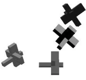
[image:3.595.359.508.430.569.2]The application may be considered as consisting of an object, of type Animation. This Animation object represents a "world" in which entities exist, move around and interact depending on their physical properties, and are rendered and displayed on a 2-dimensional display.
Figure 1. Some sample entities
- The active collision lists: one or more lists of potential collisions created from the all-pairs table. These consist of all pairs of entities suspected of colliding, due to an overlap of their bounding boxes, but which need further processing by our intersection-testing algorithm to determine whether they are really colliding or not.
- The real collision list, which contains all pairs of entities that have been detected as really colliding.
The main methods/operations that an Animation object can perform are Construction/Initialisation and Execution. A new animation can be instantiated, specifying exactly how the "world" should be, i.e. number of objects, dimensions of the box, initial viewing parameters. The objects will be given their initial positions in the world, and the collision lists and tables will be set to reflect the interactions of the objects. Once the world has been created, with all the objects in it, the animation may then begin. In its simplest form, execution consists of the following loop:
DO
- Update positions of all objects
- Update all-pairs table by testing object bounding boxes for overlaps in all three dimensions
- Generate active collision list from the all-pairs table
- Process active collision list, removing collisions as they are resolved, placing detected collisions on the real collision list, and discarding those where the objects are found not to be touching.
- Process real collision list, computing the appropriate collision response for each colliding pair.
- Draw all objects
UNTILanimation is terminated.
The Entity objects contain all information about the entity, such as position, size, translational and rotational velocity, colour, material, along with a pointer to an object of type Sphere, which will be the root of the sphere tree that approximates it. We have used a very simple volumetric representation for the entities in our application. Each entity is defined by a 3-dimensional array of 1's and 0's, a 1 indicating the presence of a cube, a 0 representing the absence. An entity thus modelled can be translated and rotated in an identical way to general polygonal models, but this representation simplifies the tasks of rendering, updating and generating sphere-trees greatly, and it is for this reason that we chose this scheme. Figure 1 shows some entities modelled in this way. However, the collision detection routines are designed to work with any sphere-trees generated from any type of model. Therefore, our work may easily be adapted to work in more general cases. The main methods/operations that an object of type Entity may perform are:
- Initialisation
- Set initial properties, i.e. colour, position, etc...
- Generate sphere tree, centred at origin.
- Update
- Render
The Sphere objects are the building blocks of the sphere hierarchies that approximate an entities, described in detail in section 3.3. A sphere contains the information about its radius, its centre relative to the origin, and its centre relative to the entity in its updated state. The sphere also contains pointers to other spheres, allowing the sphere tree to be built up recursively. The Collision
objects are nodes which may be linked together to make a dynamic list. These objects consist of:
- Two pointers to objects of type Entity, i.e. to the entities involved in the collision
- A pointer to the previous collision in the list (if any).
- A pointer to the next collision in the list (if any).
- A sphere hit list (see section 3.3)
- The centre of collision (see section 3.4)
- The distance of the centre of collision from the (estimated) fixation location
- The priority of the collision.
- The status of the collision (i.e. colliding, not colliding, or further processing required).
The main methods/operations that an object of type
Collision may perform are:
- Initialisation
- Maintain the links to the previous and next collisions in the list
- Intersection test: Tests one level of one sphere tree against one sphere on the other tree. Section 3.3 discusses the sphere-tree intersection algorithm in more detail.
- Set collision priority: This is where we will use the perceptual model, which is based on the results of psychophysical and physiological studies.
3.2 Broad Phase Collision Detection
For the broad phase of our collision detection algorithm, we use the “Sweep and Prune” algorithm proposed by [Cohen et al. 95]. This algorithm is based on the observation that:
For two 3-dimensional objects to overlap in 3-dimensional space, their 2-dimensional projections onto each of the xy, xz, and yz planes must overlap in all three cases.
sorting algorithm for previously unsorted lists, such as
Quick Sort. Any intervals that overlap are then detected, and if overlaps occur in all three dimensions for a pair of bounding boxes, the Narrow Phase is triggered.
At each subsequent iteration of the application, bounding boxes are updated, and appropriate changes made to the interval lists. Due to inter-frame coherence, and the fact that the lists were previously sorted,
Insertion Sort is used to keep them sorted. Again, overlaps in all three dimensions will trigger the Narrow Phase of the algorithm. One issue which arises is whether to use Fixed-Size bounding cubes, which are large enough to hold the convex object at any orientation, or
Dynamically-Sized bounding boxes, which will be
recomputed at every frame to be the smallest axis-aligned box that contains the object at its current orientation. Although dynamically sized boxes are more accurate, they add a computational load at each frame. Fixed-sized cubes are simpler to update, but may give rise to many unnecessary Narrow Phase collision tests. The choice of bounding volume may depend on the shape of the object. If it is almost spherical, the fixed cube fits it well, and if it’s long and thin, dynamically sized rectangles fit it better, and give rise to fewer overlaps. Perhaps both could be used, with each object being bounded by the most suitable volume.
The number of objects moving in the scene may also be a factor. [Cohen et al. 95] claim that if many objects are moving, the computational burden of updating bounding volumes at each frame could significantly degrade performance, whereas if only a few objects are moving, the reduction in Narrow Phase collision tests achieved by using tighter bounding boxes, outweighs the computational cost of computing the boxes. We choose to use fixed-size bounding boxes for our application, as we will be animating large numbers of entities.
3.3 Sphere trees.
Spheres are frequently used in computer graphics as approximations to objects. One reason is that it is very simple to test for intersections between them. Another more important reason is the fact that they are rotationally invariant. Because of this property, it is possible to build a hierarchy of spheres to approximate any non-convex object once in a pre-processing phase, centred at the origin. Whenever we wish to test for a collision between two entities, we translate and rotate the centres of the spheres on each approximating tree as we need them, and test for intersections between them
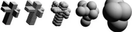
For the narrow phase of our algorithm, we have developed an interruptible algorithm based on sphere trees. We have adapted a "staircase" algorithm from [Palmer and Grimsdale 1995], and have made it interruptible, as in [Hubbard 1995]. The sphere trees are generated during a pre-processing phase, each tress consisting of 4 levels of spheres, each level representing a closer approximation to the surface of the object (see Figure. 2).
3.3.1 Building Sphere Trees
[Hubbard 1996] lists three requirements for generating hierarchies of spheres:
1. The pre-processing phase must be automatic, with no
user-intervention necessary
2. The hierarchy must be structured in such a way as to make searching it efficient, with each level eliminating the need to search a significant subset of the next level
3. Each hierarchy should fit the entity as tightly as possible.
Because of criterion 2, (i.e. efficient searching and elimination at each level), a tree is the obvious data structure to use. Another possible structure is a Directed Acyclic Graph (DAG) in which parents can share children. In our design, each sphere in the tree contains a pointer to the first sphere in its child list. If this sphere is a leaf, this pointer will be NULL. In turn, each sphere contains a pointer to its parent (NULL for the root), and to its next sibling in the sibling list, if any.
[image:5.595.311.535.630.685.2]Sphere trees may be built so that children must fully cover all parts of the object that their parent does, or simply a subset of those parts. We have chosen to build our sphere-trees to represent a conservative over-approximation of the object’s exposed volume. Collisions involving any uncovered areas of the surface will remain undetected by the detection system so we require that our hierarchy of spheres at each level encompasses the object completely. On the other hand, we need to ensure that there are no redundant spheres in our sphere-tree such as those that are occluded by other spheres and thus play no part in the actual collision detection. The accuracy of both collision detection and response in our system is dependent on our sphere-tree representations of the objects in our system so we would desire that the sphere trees fit the object as tightly as possible. At the same time, limiting the number of nodes at each level of the sphere tree directly implies less computation for the detection mechanism so a simple model would also be desirable. What we require then is an automatic method of generating a sphere-tree representation, which will be as tight as possible and yet simple enough so that it would be feasible for use in our real-time application. The method implemented in our system is based on octree subdivision of the object volume.
Figure 2. An entity and 4 levels of its sphere-tree
level of the octree and represents the bounding cube for our object. This cube is then subdivided into eight equal partitions or octants. If any of these partitions contains any part of the object then it is enabled as a node on the octree. Each octant is then recursively subdivided in a similar way up to the level of decomposition required. Determining whether or not a 3D sub-partition contains any part of the object can be done in several ways depending on the method initially used to describe the object’s volume (e.g. face intersection tests). In our present system we require that each object has a voxel representation of its volume so determining whether or not to attach a child node simply involves checking if the corresponding octant contains an enabled voxel.
Once the required octree has been generated, it is a simple matter to find the smallest radius of sphere required to completely encompass any particular node of the octree. For regular cubes (side
α
) the required radius is simply:2
3
α
=
r
For a cuboid of dimensions x, y, z :
2
2 2 2z
y
x
r
=
+
+
Finally we remove all nodes from the octree which are occluded on all sides by other nodes and the finished sphere-tree is obtained by generating all the spheres corresponding to the remaining nodes of the octree.
3.3.2 Sphere-Tree Intersection Algorithm
We test for intersection between two sphere trees as follows: Take two sphere-trees, tree 1 and tree 2, which approximate two objects whose bounding boxes overlap in all three dimensions. This has caused an object of type
Collision to be created, with pointers to the roots of both trees. Each collision object contains a pointer to a list of
sphere hits. A sphere hit contains a record of the current state of the collision object, i.e. what spheres on one tree must be tested against what spheres on the other tree. This consists of a target sphere on one tree, and a test list of spheres on the other tree.
At the start of the algorithm, the list consists of one sphere hit, i.e. the root of tree 1 is the target, and the root of tree 2 is the test list. If these do not intersect, then there is no collision between the objects. If they do, a new sphere hit is added to the collision's sphere hit list, the root of tree 2 becomes the target sphere, and the children of the root of tree 1 now become the test list. Continuing on in this fashion, every time an intersection is found between a target sphere and a member of the test list, a new sphere hit is created with the intersecting member of the test list becoming the new target sphere, and the children of the old target becoming the new test list. In this way, the algorithm is fully interruptible, allowing the detection to descend one level of one tree at a time,
reducing the complexity of the algorithm, and enabling a fast, albeit approximate, response when necessary.
3.4 Interruptible Collision Detection
The application performs the broad-phase testing, and creates a list of collision objects called the active collision list. This is a linked list of all collisions that have not yet been resolved. As collisions are resolved, they are placed on the real collision list if a real collision was detected, or are destroyed, if it has been determined that the entities are definitely not colliding. If all collisions are fully resolved, the frame-rate will be highly variable. Therefore, it is sometimes desirable to interrupt processing when a target time has elapsed. The control of the processing order of collisions on the active collision list is determined by the chosen scheduling mechanism.
3.4.1 Adding Interruption
At any point in time during collision processing, there will be unresolved collisions on the active list, and resolved collisions on the real list. At some point the application will deem that collision processing should stop. In our case the criterion for stopping is when a pre-defined target time has been exceeded. However, other criteria could just as easily be used. When the request for an interruption is generated, the collision processing must stop, and this will leave us with a list of real collisions and a list of unresolved collisions still on the active collision list. We have chosen to treat these collisions as real collisions. In this case all the active collisions are added to the end of the real collision list. We could just as easily have chosen to reject these collisions, thus allowing inter-penetration, but for reasons explained in later chapters, we will accept all unresolved collisions as being real. There are four possible results at each iteration of the test for a collision object.
1. An intersection is detected between two leaves of the trees. In this case the objects are deemed to be colliding, and the collision is resolved. The collision will be removed from the active collision list, and added to the real collision list.
2. No intersections are detected between any of the targets of each sphere hit and the members of the test lists. In this case, the objects are definitely not colliding, and the collision is resolved. The collision is removed from the active collision list and destroyed.
3. An intersection is detected between the target sphere and a test sphere of at least one sphere hit, but at most one of the spheres is a leaf, so the collision test is non-conclusive. In this case, new sphere hits are created, and the collision remains on the active collision list for further processing if needed.
Although our application creates 4 levels of sphere trees for every object, the intersection algorithm has been designed to handle intersection tests between two sphere trees of unequal height. This is handled by stopping the cross-over in the algorithm, i.e. instead of adding a new sphere hit between the children of the old target, and the intersecting member of the test list, if the old target has no child, the new sphere hit is created with the old target remaining as target, and the test list is the child list of the intersecting member of the old test list. The target remains the same until an intersection is detected between it and a leaf of the other sphere tree, or until an interruption occurs. This means that in the future, more complex objects can be approximated by more levels of more spheres, and more simple objects by only a few levels (or even just one, in the case of spherical objects).
3.4.2 Measuring Inaccuracy and Prioritising Collisions
This application provides a framework within which different collision detection, prioritisation and scheduling algorithms may be implemented and evaluated for computational and perceptual performance. A model of collision perception based on eccentricity and separation is used both to prioritise collisions, and also to estimate perceived inaccuracy [O'Sullivan 1999]. This model, plotted in figure 3, has been validated by psychophysical means, and represents a good approximation to a human's perception of collision anomalies (i.e. repulsions) at different eccentricities and separation distances.
When considering the inaccuracy present in a frame of an animation, we must distinguish between
geometrical inaccuracy∇∇, and perceived inaccuracyP. The geometrical inaccuracy in a scene is an estimate of the overall three-dimensional error that has been incurred by accepting non-collisions as real, causing entities to repulse without touching. It can be estimated by summing the sizes of all potential gaps left during such "non-collisions". In our applications, we cannot calculate the exact size of the gap between two colliding entities, as this would take an excessive amount of time and defeat the purpose of approximate collision testing. Instead, we can use the information available to us to estimate an upper bound on the maximum gap size between two entities, i.e. the maximum 3D separation between two objects caused by an incorrectly detected collision. We use the three-dimensional distance between the centres of the last two spheres found to be intersecting from the sphere-trees of each colliding pair, or the distance between the centres of the two entities if collision testing is interrupted before any spheres have been tested. We estimate the geometrical inaccuracy ∇∇ in a given frame by simply summing these distances. Hence, the further down the sphere-tree hierarchy each collision is allowed to progress, the more accurate the estimate will become. Alternatively, we could pre-compute the Hausdorff distance for all spheres in each tree (as in [Hubbard 1995]), and use the sum of these distances as our estimate.
Not all collision inaccuracies contribute equally to the inaccuracy perceived by the user in a single frame of an animation. Hence, the perceived inaccuracy P present in two frames of an animation with identical geometrical inaccuracy ∇∇, may be quite different depending on how the frame is viewed. Eccentricity e is the distance from the viewer's fixation point. Separation can be estimated by maximum 2D gap size g, i.e. the maximum separation between two objects projected on-screen which is caused by an incorrectly detected collision. It has been shown in [OSullivan 1999] that eccentricity and separation are the two most important factors which affect perceived inaccuracy, when large numbers of similar objects are being animated. Work is ongoing to determine the effect of other factors, in other circumstances.
If two spheres are interpenetrating, we find the midpoint on the line segment inside the intersection (see Fig. 4). We call this the Centre of Collision. We track the user's gaze, so we know the fixation point F for each frame, expressed as an x,y location on screen. We can therefore calculate the eccentricity e as follows: We find the x,y location in screen co-ordinates of the centre of collision projected onto the view-plane, then e is simply the 2-dimensional distance from F of the centre of collision. Collisions closer to the fixation point contribute more to the perceived inaccuracy of a frame than those further away and hence should receive higher weighting. Collisions further from Fshould receive lower weighting.
Similarly, the size of the maximum on-screen gap,
[image:7.595.327.508.488.599.2]g, may also be used to weight each collision, with larger gaps contributing more to inaccuracy than smaller ones. We calculate an upper bound on the 2-dimensional gap size as follows: We take the centres of the last two spheres found to be intersecting, and calculate the 2-dimensional distance between their projections onto the screen.
Figure 3. Perceptual function, f, showing the relationship between eccentricity e, and gap size g, measured in pixels. The function f(e g) shows the probability of the viewer noticing a gap of that size at that eccentricity.
3.4.3 Scheduling
The key to controlling the collision inaccuracy perceived by a viewer in a given frame of an animation lies in the scheduling method adopted. We have seen in previous sections that upon completion of the broad phase of
f(e,g) = g / (exp(e/100))
0.0 1.0
0 320
e
f(e,g)
10 20 30
collision testing, an active list of collisions exists, one collision object for each pair of entities whose bounding boxes overlap. In [Hubbard 1995] round-robin scheduling is used, i.e. this list is resolved in round-robin order, descending one level in the hierarchy of every sphere tree at each iteration of the algorithm. However, no account is taken of the perceptual importance of each collision. Other strategies are: sequential scheduling collisions are resolved fully one by one until completion or interruption. Again, perception is ignored with this strategy. In perceptually sorted sequential scheduling, perceptual information is used to schedule collision testing. A perceptual importance is attached to each collision, based on some criteria, and the active collision list is then sorted based on this priority. Sequential scheduling is then used, but now the collisions which are most important perceptually will be resolved first, leaving the more unimportant collisions to be resolved only if there is time left. However, a significant overhead is incurred through the sorting process, and has been shown to reduce the time for collision detection so much as to degrade, rather than improve performance.
Another strategy is to generate not one active collision list, but a set of priority queues, and to round robin within them. The perceptual model is used only to decide which queue a collision belongs to, thus reducing the computational overhead. A higher priority queue would be resolved first, and only when all collisions on that queue have been resolved would the next highest queue be handled. This is called priority queue scheduling. It has been shown that priority queue scheduling, using the above model of collision perception to measure inaccuracy and to prioritise collisions, is the most effective scheduling mechanism, with perceived inaccuracy being approximately halved for large numbers of objects.
3.5 Collision Response
A simple way of achieving refineable collision response might be by treating all of the objects in our system as the union of spheres represented by their sphere trees. This seems like a logical approach as we have already made this assumption in the detection phase. Not only will we inherit all the data (variables and pre-computed constants) but we also have a built in consistency to our system. It becomes possible to interleave the two processes of detection and response (including all contact point determination etc.) and make our whole system more cohesive. This is desirable in a time-critical system as it would allow for more interaction between the two processes. Certain calculations (for instance determination of gap-size, and the centre of collision) would be useful to both detection and response mechanisms and interleaving the two processes would avoid repetition and make the system more efficient.
A simplified impulse based method is used to calculate responses [Baraff 97][Baraff & Witkin 98] given the point of collision and the collision direction. The full details of the collision response calculations fall outside the scope of this paper and we only describe here
the process involved in obtaining the required data used in these calculations. The details required for an adequate level of response calculations are outlined below:
i. mass (or relative mass of objects) ii. centre of mass of objects
iii. moment of inertia of objects
iv. state of colliding objects at the instance of collision (e.g. velocity, position).
v. the points of collision and
vi. the direction of the applied impulses
[image:8.595.308.525.426.571.2]Mass and centre of mass are determined at the pre-computation phase; moment of inertia can be computed relatively quickly based on the current orientation of the object and a pre-computed constant. We treat the objects as if they actually were a union of spheres and use this to approximate the other required parameters (i.e. the collision direction, and collision points). Due to the very nature of our collision detection system the data passed on to the collision response system will at best be an approximation for all but the highest priority collision events in the scene. Once our detection system has indicated that the nodes of two sphere trees have collided that is when the collision resolution phase begins. We cannot justify doing further intersection tests (e.g. checking for polygon level intersections) to determine the exact nature of the collision, as that would defeat the purpose of our interruptible algorithm. However given the positions of the colliding spheres, a fair approximation of the collision data can be made.
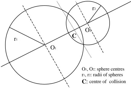
Figure 4: A quick approximation of the collision data (given the identities and properties of the colliding spheres on the sphere trees)
Collision direction is taken as line joining the centres of the two spheres (see Fig. 4). The collision point C lies on this line and divides the line between O1 and O2 in
proportion to the radii of the spheres. We have illustrated the situation when we let the sphere trees interpenetrate, however the same principles would be applied if we forced them to repulse at a distance. Note: similar calculations are done to compute the “centre of collision” in the Collision Detection phase. Using this method, we do not require a separate mechanism for prioritising events for the purposes of response calculation. This has been done for us at the detection phase, as the more
O1
O2
r1
r2
C
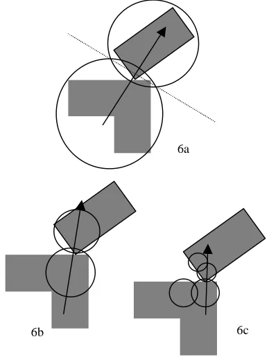
important collision events will have been resolved to a deeper sphere-tree level. The deeper we go down the sphere tree, the more accurate our representation of the object and hence our approximations of the collision point and collision plane. In Figure 5, a, b and c show different levels of detail for the collision data approximation. However resolving the two impulses leads to a reasonably accurate approximation of the actual impulse.
6a
[image:9.595.78.272.164.422.2]6b 6c
Figure 5: How the response data automatically gets refined as we go deeper into the sphere tree
The response mechanism will only have an approximation of the actual values at the moment of collision. A conservative approximation of the state of the objects, the point of collision and the collision plane would be obtained by taking the states of the objects the frame before inter-penetration of sphere-trees was detected. This would ensure that no inter-penetration of the actual objects ever takes place. However, as the sphere tree bounds themselves are conservative approximations of the space occupied by objects such a restriction would even further increase the inaccuracy. A simpler approximation would be the states of the objects at the instance when collisions were detected. This would mean that our spatial model of the objects (i.e. the sphere tree representations) would in fact overlap over the course of the animation. Again because the spheres are overestimates of the object volume, overlap to a certain degree is acceptable. There is no way of determining for certain if the actual objects will overlap when sphere trees intersect but it may be preferable to have objects overlapping during collisions than to have a large gap-size.
Inter-penetration in the system is a direct result of being limited to discrete time-steps; a limitation which all real-time systems suffer from. It is the single largest
source of inaccuracy in our system and we would want to minimise this as much as possible. If our time-steps were arbitrarily short or the velocities of entities in our system were arbitrarily small, inter-penetration and the resulting inaccuracy could be reduced to an acceptable level. This cannot always be guaranteed in a real-time system and the exact values, if required, must be obtained by performing some form of backtracking or interpolation to determine the states of the objects at the exact instant of collision (i.e. before they actually interpenetrate).
4 Conclusions
In this paper we introduced a method of collision handling which produces a refineable approximation of the behaviour of objects due to collisions. The computing cost for the response phase is fairly minimal so there is more time available for other parts of the system including collision detection and rendering, making it suitable for an interactive real-time system. An approximate model of collision response is implemented in the attempt to generate plausible motion as opposed to mathematically accurate motion, which would be computationally more expensive. This is usually justified as there is always a certain degree of uncertainty in the real world which prevents us from predicting how exactly an object will behave. The question that needs to be answered is how to get the best return from the speed-accuracy trade-off.
The model of collision perception which we use is very specific. It represents typical human reactions to collision anomalies, where large numbers of homogeneous objects are being animated. Work is in progress to make it applicable in more general cases. Other factors, such as location and direction of motion, velocity, acceleration, colour and luminance can have very strong effects under certain circumstances, and if necessary must also be included if the model is to be truly representative of human perception of collisions.
At present all collision events are prioritised on a scheme based on tests, which were done with a number of subjects to determine how sensitive they were to approximate collision events occurring on different parts of the scene. So far, this has largely been a test of how collision detection can be prioritised effectively. Similar tests might be done to determine how sensitive viewers are to approximations of particular responses to collisions and implement this in our prioritisation scheme. Inter-penetration is a major source of inaccuracy and needs to be minimised (or ideally eliminated) in order to ensure the robust and consistent operation of our system. However it would be undesirable to err too far on the side of caution as this too affects accuracy and more so the believability of the animation. Some means of closely approximating the collision point needs to be implemented in real-time by backtracking or interpolation.
number of colliding objects) which needs to be addressed. Applying changes successively when there are many interdependent collisions becomes complicated and if interrupted by the scheduler leads to inconsistencies. Our current approach therefore is to apply the changes simultaneously by taking account of all colliding objects before any changes are applied. This method works if there is a lower level of Collision response to fall back on in the case where the response phase is interrupted.
Further behavioural detail still needs to be added to the system to increase the realism and the general applicability of the system. For instance, friction forces during collisions, gravity and elasticity of collisions have been experimented with but are not fully implemented in the current system. Such factors would undoubtedly add further complexity to the system and we need to investigate how much more complexity we can afford and how we might also cull these behaviours in a fully adaptive real-time system.
Bibliography
[Baraff 97] Baraff, D. Physically Based Modelling. SIGGRAPH ’97 Course Notes.
[Baraff & Witkin 98] Baraff, D. and Andrew Witkin. Physically Based Modelling. SIGGRAPH ’98 Course Notes.
[Barzel et al. 1996] Barzel, R. Hughes, J.F. Wood, D.N. (1996) Plausible Motion Simulation for Computer Graphics Animation. Computer Animation and Simulation '96. 183-197.
[Chenny 97] Chenny, S. Culling Dynamical Systems in Virtual Environments. 1997 Symposium on Interactive 3D Graphics.
[Cohen et al. 1995] Cohen, J.D. Lin, M.C. Manocha, D. Ponamgi, M.K.(1995) I-COLLIDE: An Interactive and Exact Collision Detection System for Large-Scaled Environments. Proceedings of ACM Int. 3D Graphics Conference. 189-196.
[Funkhouser and Sequin 1993] Funkhouser,T.A. Sequin, C.H. (1993) Adaptive Display Algorithm for Interactive Frame Rates During Visualization of Complex Virtual Environments. SIGGRAPH '93 247-254.
[Hubbard 1995] Hubbard, P.M. (1995) Collision Detection for Interactive Graphics Applications. IEEE Transactions on Visualization and Computer Graphics. 1(3) 218-230.
[Hubbard 1996] Hubbard, P.M. (1996) Approximating Polyhedra with Spheres for Time-Critical Collision Detection. ACM Trans. on Graphics, 15(3) 179-210.
[Klosowski et al. 1998] Klosowski, J.T. Held, M. Mitchell, J.S.B. Sowizral, H. Zikan, K. (1998) Efficient Collision Detection Using Bounding Volume Hierarchies
of k-DOPs. IEEE Trans. on Vis. and Comp. Graph. 4(1). [Krishnan et al. 1998] Krishnan, S. Gopi, M. Lin, M. Manocha, D. Pattekar, A. Rapid and Accurate Contact Determination Between Spline Models using ShellTrees. in Proceedings of Eurographics'98.
[O'Sullivan 1999] O'Sullivan, C. A Model of Collision Perception for Real-Time Animation. Technical Report TCD-CS-1999-01, Trinity College Dublin, January 1999.
[O'Sullivan and Reilly 1997] O'Sullivan, C. Reilly, R. REACT: REal-time Adaptive Collision Testing,, D. Thalman, M. van de Panne (eds.) Computer Animation and Simulation '97 163-175.
[Mirtich 96] Mirtich, B. Impulse Based Dynamic Simulation of Rigid Body Systems. Phd Thesis, University of California, Berkeley, 1996.
[Mirtich and Canny 95] Mirtich, B. and Canny, J. Impulse-based Dynamic Simulation. In Proceedings of 1995 Symposium on Interactive 3D Graphics. 181-188.
[Palmer and Grimsdale 1995] Palmer, I.J. Grimsdale, R.L.(1995) Collision Detection for Animation using Sphere-Trees. Computer Graphics Forum, 14(2) 105-116
[Quinlan 1994] Quinlan, S. (1994) Efficient Distance Computation between Non-Convex Object. Proceedings International Conference on Robotics and Automation. 3324-3329.