www.elsevier.com/locate/cag
Author’s Accepted Manuscript
Rendering fur directly into images
Tania Pouli, Martin Pražák, Pavel Zemˇcík, Diego Gutierrez, Erik Reinhard
PII: S0097-8493(10)00087-7
DOI: doi:10.1016/j.cag.2010.06.004 Reference: CAG 2023
To appear in: Computers & Graphics Received date: 3 June 2009
Revised date: 4 June 2010 Accepted date: 7 June 2010
Cite this article as: Tania Pouli, Martin Pražák, Pavel Zemˇcík, Diego Gutierrez and Erik Reinhard, Rendering fur directly into images, Computers & Graphics, doi:10.1016/j.cag.2010.06.004
Rendering Fur Directly into Images
Tania Pouli1, Martin Praˇz´ak2, Pavel Zemˇc´ık3, Diego Gutierrez4, Erik Reinhard1
Abstract
We demonstrate the feasibility of rendering fur directly into existing images,
without the need to either painstakingly paint over all pixels, or to supply
3D geometry and lighting. We add fur to objects depicted in images by first
estimating depth and lighting information and then re-rendering the resulting
2.5D geometry with fur. A brush-based interface is provided, allowing the
user to control the positioning and appearance of fur, while all the interaction
takes place in a 2D pipeline. The novelty of this approach lies in the fact
that a complex, high-level image edit such as the addition of fur can yield
perceptually plausible results, even in the presence of imperfect depth or
lighting information.
Key words: Picture/Image Generation, Scene Analysis
Email addresses: [email protected](Tania Pouli),[email protected](Martin Praˇz´ak),[email protected](Pavel Zemˇc´ık),[email protected](Diego Gutierrez),
[email protected](Erik Reinhard) 1University of Bristol
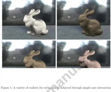
Figure 1: A variety of realistic fur styles can be achieved through simple user interaction.
1. Introduction 1
Many applications require the editing of images. Notorious are the
touch-2
ups of photographs in glossy magazines, but also in the film industry effects
3
post-processing is taking ever more advanced forms. A trend in computer
4
graphics is the emergence of algorithms that enable high-level image
manip-5
ulations [19], including adjustment of the lighting in images [6], re-texturing
6
of objects [7, 29], and more general material replacements [11].
7
These algorithms typically require some form of depth extraction [30],
8
which on the basis of a single image is an under-constrained problem. Thus,
approximate results are inevitable. The key to successful image
manipula-10
tions is therefore not to achieve physical accuracy, but aim for visual
equiv-11
alence [24], i.e. the resulting images may be physically wrong, but should
12
appear perceptually plausible. The human visual system (HVS) helps here,
13
as it is in some cases unable to accurately predict specific features in cluttered
14
environments [21]. At the same time, the HVS makes several assumptions on
15
the nature of the environment, for instance that the geometry is internally
16
consistent [12] or that the viewpoint is chosen in accordance with human
17
physique [9]. Finally, globally convex objects are normally perceived
un-18
der diffuse lighting according to the dark-is-deep paradigm [13], suggesting a
19
relationship between luminance and shape.
20
After depth extraction, lighting and/or shading can be estimated from the
21
image, for instance by using the background of the object that is being edited
22
[11]. An environment map can be constructed using inpainting to remove
23
the object [3, 5, 26]. Recovery of lighting is a necessarily under-constrained
24
problems as well. With approximate lighting and geometry recovered, new
25
materials can be inserted, and the rendering equation can be re-evaluated,
26
possibly using importance sampling on the recovered environment map to
27
determine a selection of relevant light sources [20]. The result is then an
28
image where the materials of objects have been replaced, but the lighting
29
and geometry are preserved as well as possible.
30
We are interested in rendering fur directly into images, as shown in
Fig-31
ure 1, for several reasons. Fur is a feature that would be very difficult to
32
draw by hand. Although modern image editing applications make such edits
33
possible, it is a difficult and time consuming process even for the most skillful
artists. Several commercial packages exist to help artists create
convincing-35
looking hair and fur images, based on a traditional 3D representation of a
36
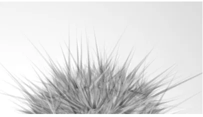
scene (such asMaya’s Paint Effects, orShave and a Haircut). In contrast to
37
these tools, our method is designed as a post-production process, and uses
38
a single 2D image as input. Our fur editing technique does not require the
39
artist to switch to a 3D environment, and thus it could be easily integrated
40
in any existing 2D pipeline.
41
Further, the semi-procedural addition of geometry to an image raises
42
the question of how well the new geometry itself would be able to provide
43
masking effects [8], which are required to camouflage the limitations of the
44
depth extraction algorithm. We investigate how different materials affect the
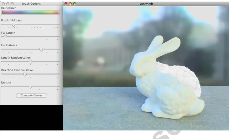
45
estimation of depth and in turn how these effects are counteracted by varying
46
fur properties.
47
2. Algorithm 48
Adding fur to an image requires several stages of processing, beginning
49
with image analysis, optional creative user input, fur generation, and
render-50
ing. Each of these steps is discussed in the following sections.
51
2.1. Image Analysis
52
Before any rendering can take place, ideally a 3D description of the scene
53
would be required. However, the best we can achieve with a single image
54
as input is the computation of an approximate 2.5D depth map, describing
55
the distance between the camera and the nearest surface for every pixel
56
of the input image. This is the classic shape-from-shading problem, which
57
is normally formulated to enable recovery of 3D shape from an image and
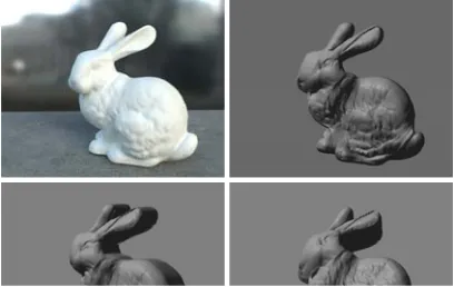
Figure 2: Depth maps are rendered from the original viewpoint (top left), which helps to mask artifacts that are more visible from other viewpoints (bottom row). (Note that for illustration purposes, all depth maps in the paper are rendered as a surface with a single light source.)
potentially allow re-rendering of that shape from a different viewpoint. In our
59
case, we will always re-render the image from its original viewpoint, which
60
relaxes the requirement for accuracy somewhat. This is due to the bas-relief
61
ambiguity, the difficulty the HVS appears to have to distinguish surfaces
62
that are related by affine transformations along the line of sight [2]. Thus,
63
oblique illumination causing shearing of the depth map may go unnoticed
64
(Figure 2). These observations were exploited by Khan et al. [11] where
65
luminance values were filtered in order to create a depth map. We follow their
66
approach, which begins by converting the luminance channel of the image
67
into sigmoidal space, followed by the application of a bilateral filter [27].
68
The sigmoid is then inverted, followed by an optional reshaping step of the
69
luminance signal to obtain the final depth map. This sequence of processing
is sufficient to produce adequate depth maps. The bilateral filtering stage
71
is used exclusively to remove high-contrast high-frequency content, which
72
is typically associated with textured surfaces, and therefore does not carry
73
shape-related information.
74
2.2. Parametric Fur Generation
75
We provide two approaches to the generation of fur. In the first case, a
user-supplied matte can be used to specify where in the image fur should
be inserted. The depth map is then computed for this region, as shown in
Section 2.1, and hairs are created and attached to the image algorithmically.
To achieve this, each 2 × 2 block of depth values is converted into two
triangles, thereby converting the depth map into a polygonal mesh. To each
triangle we attach a number of hairs, determined by the required density, a
random variation, and the area of the polygon. With the aid of barycentric
coordinates defined on the triangle, the placement of the hairs is randomized
as well:
h=ξ1p0+ξ2p1+ (1−ξ1−ξ2)p3 (1)
where p0, p1 and p2 correspond to the vertices of the triangle and ξ1, ξ2
76
are two variables randomly selected from a uniform distribution in the range
77
[0,1] such thatξ1+ξ2 ≤1. From the polygonal model, surface normals are
78
computed for each vertex. These are then linearly interpolated and
normal-79
ized to compute the surface normal n for each hair position h. Finally, we
80
compute a desired length for each hair, which can either be specified as a
81
single numeric value, or by supplying a per-pixel map.
A hair is represented by a point hindicating the position of the root, the
surface normaln, a direction randomization vectorrand lengthl. These
pa-rameters, as well as a ”gravity” vectorg, which bends hair in a user-specified
direction, form the input to a particle-based model which then generates the
hair by Euler integration [16]. For relatively short hair, a simple Newtonian
model suffices:
d2
dt2p(t) =g l, withp(t0) =h, d
dtp(t0) =
n+r
n+rl (2)
where the position p(t) represents the resulting function of particle
simula-83
tion, with discrete values t determined by the integration step (usually 0.02
84
for normalized vector n and g < 10), with the direction randomization
85
vector rsatisfying r<0.1.
86
For longer hair, the interaction between individual hairs as well as the
87
underlying mesh should be considered, and a more advanced particle model
88
involving springs and friction would be more appropriate. However, for fur
89
we ignore these interactions as their effect can be achieved by randomizing
90
the parameters for each hair, which significantly speeds up the simulation.
91
The result of the particle model for each hair is a set of points representing
92
its shape which is then converted to a cubic B´ezier curve. For the purpose of
93
rendering, we represent these curves as flat ribbons that are always facing the
94
camera [4]. This approach is taken to minimize aliasing artifacts. Figure 3
95
shows a detailed view of the fur.
96
2.3. Creative User Input
97
On living creatures, hair and fur shows many irregularities that are
dif-98
ficult to represent procedurally. In particular, the orientation of fur varies
Figure 3: Fur is rendered as flat ribbons facing the camera. Some random luminance and length variation improves the photorealism of the fur.
across the body. Further, the physical values for the density, length or
thick-100
ness of the hair do not translate directly into parameters that can be inserted
101
into our algorithm. This is due to the fact that by necessity the units our
102
algorithm uses are pixel values. The required hair density or length, on the
103
other hand, depend on the resolution of the photograph and the distance
be-104
tween the object and the camera. Similar arguments can be made for other
105
hair-related parameters such as hair thickness.
106
In addition, the design of fur may require creative input, determining
107
the average length, direction, and density, for the purpose of telling a story.
108
Therefore, for both technical and creative reasons, it is desirable to have
con-109
trol over the placement and appearance of fur, beyond the simple adjustment
110
of parameters.
111
To this end, we have implemented a simple-to-use interface where the
112
user can draw and customize fur directly on the image. Brush strokes control
113
the positioning and direction of the fur. Additionally, using a set of sliders
114
the hair length, color, density and flatness can be adjusted for each stroke
115
(Figure 4).
Figure 4: Our tool displays the image on which fur is drawn using brushes (right). The parameters to the brush are also shown (left). Note that as depth is available at the time of drawing, the effect of painting fur on a surface is created.
With the use of the depth map, the brush strokes are converted into a
117
collection of individual hairs. The stroke itself is given by a collection of
118
pointssi, which may optionally be smoothed. From these points we compute
119
normalized stroke direction vectorsdi = (si+1−si)/si+1−si. These vectors
120
replace the gravity vector g in Equation (2). Hair generation is otherwise
121
identical to the algorithm outlined in the preceding section. This approach
122
maps the direction of the brush stroke to the direction of the hair, while
123
taking into account the shape of the object. In essence, the brush stroke can
124
literally be viewed as a hair brush!
2.4. Rendering
126
The rendering system is supplied with a potentially very large number of
127
hairs which have to be rendered and then composited back into the original
128
image. As we are placing hairs into photographs, we require a
state-of-129
the-art rendering algorithm so that the rendered content will be difficult to
130
differentiate from the photograph. This aspect of our application therefore
131
requires much higher accuracy than was, for instance, required for depth
132
recovery.
133
One of the earliest methods for fur rendering is due to Kajiya and Kay [10],
134
using three dimensional textures. Van Gelder and Wilhelms [28] manipulate
135
fur in real time but their model can only deal with polylines. The work by
136
Lengyel et al. [15] allows for real-time rendering of fur over arbitrary
geome-137
tries, at the cost of a double pre-processing step. Lapped texture patches are
138
computed to parameterize the surface [23], followed by the creation of shell
139
textures [14]. Fur appearance at the silhouette of the objects is improved by
140
rendering additional texture cards normal to the surface near such
silhou-141
ettes. In contrast, the off-line rendering part of our method handles
silhou-142
ettes naturally and does not require any geometry or texture pre-processing.
143
Recent work by Zinke et al. [31] allows for real-time rendering of very
144
high-quality hair images by using “aggressive simplifications” of the complex
145
scattering phenomena involved. Their results are on-par with path tracing
146
results, although they also require some pre-computations: as a result, the
147
preprocessing cannot be executed for every frame, precluding our goal for
148
interactive drawing and pre-visualization of hair.
149
We experimented with two high quality rendering models, namely the
model first proposed by Kajiya and Kay [10], as extended by Banks [1], and
151
the more complex model proposed by Marschner et al. [18]. We have found
152
that the visual quality provided by the latter is closer to the appearance of
153
human hair whilst the first model corresponds better to the appearance of
154
fur.
155
Of course, this model does not render at interactive rates, which is why we
156
have fitted our user-interface with a fast pre-visualization to give the designer
157
instant feedback. While recently real-time hair rendering algorithms have
158
become available, they still require a few seconds of preprocessing [15, 31].
159
As a result, the preprocessing cannot be executed for every frame, making
160
interactive drawing and rendering of hair in full quality impossible. The
161
exception is the opacity map based technique augmented with approximate
162
sorting [25], which could be employed in our system.
163
However, the purpose of our work is to demonstrate the feasibility of
164
augmenting photographs with macro-scale structure. The choice of renderer
165
does not affect our ability to draw conclusions. For simplicity, we therefore
166
resort to a non-photorealistic pre-visualization, which does not require any
167
preprocessing, and is still accurate enough to allow the designer to envisage
168
the final rendered result. This compromise is necessary to create high quality
169
renderings, which are demonstrated in the following section.
170
The lighting can either be user-specified if high levels of control are
171
needed, or can be derived from the background pixels in the image. In
172
the latter case, the computation of light directions proceeds in a
straight-173
forward manner, given that human vision is relatively insensitive to this
174
parameter [21]. As the color of the light source is much more important, we
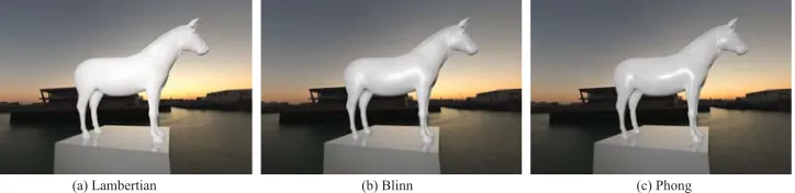
(a) Lambertian (b) Blinn (c) Phong
Figure 5: The same model was rendered using three different materials, namely a Lam-bertian surface (a), a specular Blinn surface (b) and a Phong surface (c).
follow the approach of Khan et al. [11], and subject the background pixels
176
to importance sampling to derive a small set of light sources [20]. Finally,
177
the rendered results are composited into the original image using standard
178
compositing techniques [22].
179
To ensure that satisfactory results can be achieved even with a low fur
180
density, a simple flag is exposed to the user. When enabled, a mostly diffuse
181
surface matching the color of the fur at each location is rendered underneath
182
the fur.
183
3. Analysis 184
As outlined in Section 2.1, shape is estimated based on the luminance
185
values of the object of interest in the image. To demonstrate how different
186
materials can affect the accuracy of the recovered depth we rendered the same
187
scene using three different material properties for the horse, approximating
188
Lambertian, Phong and Blinn surfaces. All other scene parameters were the
189
same for all three cases. The rendered images can be seen in Figure 5.
190
The depth map corresponding to each material was recovered using the
191
same settings across all cases (Figures 6 and 7). Figure 6a shows the ground
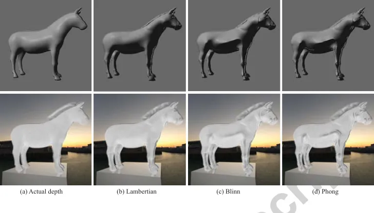
(a) Actual depth (b) Lambertian (c) Blinn (d) Phong
Figure 6: Depths recovered for each of the three materials using the same settings for all cases are shown at the top. The depth recovery parameters were chosen such that any small artifacts would be smoothed out but not highlights due to material specularity. The corresponding fur renderings can be seen at the bottom.
truth geometry for the object. Note that all the depths shown in the paper
193
are re-rendered using a specular material for demonstration purposes. As can
194
be seen, the diffuse surface (Figure 6b) allows for the most accurate depth
195
estimation as the properties of the surface are the closest to the assumptions
196
used by our shape recovery algorithm. In the other two cases however, the
197
material properties selected create specular highlights, which when converted
198
to depth, appear as sharp peaks on what should be a smooth surface.
199
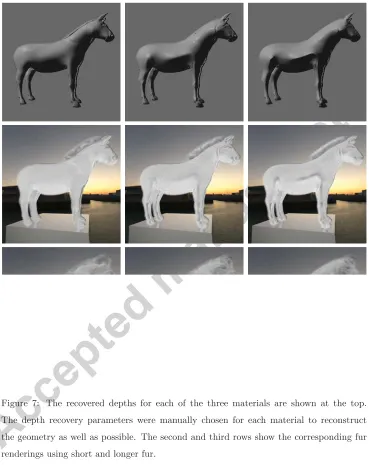
Depth was also recovered for each material using the best settings for
200
each case. These settings were chosen manually so that the reconstructed
201
geometry would be as close as possible to the ground truth (Figure 7).
202
To evaluate the masking properties of fur, we rendered fur on each of the
Figure 8: Realistic moustaches can also be achieved with our system as they have similar properties to fur. The images on the left show the original photographs.
recovered depth maps for both of the cases described above (Figures 6, 7).
204
In the latter case, fur was rendered using two different lengths that were
205
varied by approximately an order of magnitude. The HDR Visual Differences
206
Predictor (HDR VDP) [17] was employed to compare each image with the
207
respective ground truth. Detailed results and discussion of these comparisons
208
can be found in Appendix A.
209
4. Results 210
Parametric fur rendering has the advantage that little user input is
re-211
quired to generate plausible fur. A variety of styles can be achieved through
212
the provided controls as shown throughout the paper (e.g. Figures 1, 8, 9, 10
213
and 11). Fur of different colors or lengths can be combined in the same image
214
in order to create the desired effect. Additionally, with the aid of user-drawn
215
masks, it is possible to modulate hair parameters to achieve complex effects,
216
as shown in Figure 12.
Figure 9: The material of the left cushion is changed to short fur. The color of the fur is kept the same as the original material (shown on the left).
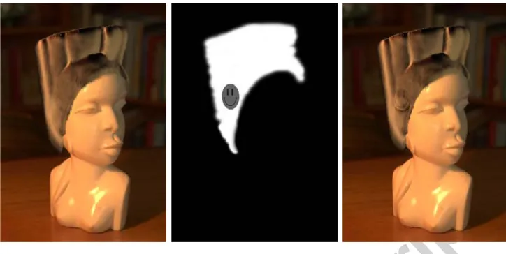
[image:17.612.127.497.266.575.2]Figure 11: Mattes can be used to modulate hair parameters. The matte shown (center) is used to alter hair length (right). The left image shows the unmodulated result.
4.1. Limitations
218
As discussed previously, our algorithm performs best when the object’s
219
material approximates Lambertian surface properties. This should be no
220
surprise as the depth estimation is based on the assumption that luminance
221
relates to depth. This assumption does however break in several occasions.
222
The simplest case is the presence of specular highlights on the object
223
surface, which can cause spikes in the recovered depth. These can be
re-224
moved by employing a simple scheme such as the one proposed by Khan et
225
al. [11]. More challenging scenarios arise when complex materials are present.
226
For instance transparent or translucent surfaces would not satisfy the depth
227
recovery assumption, leading to incorrect shapes. Additionally, highly
reflec-228
tive surfaces would require reflection separation in order for the luminance
229
of the surface to be usable.
230
Other challenging cases arise when the illumination in the scene is highly
Figure 12: Examples of the wide variety of styles that can be achieved using our fur drawing tools. The original image is shown at the top left and the re-rendered depth (shown at a skewed angle) at the bottom left.
directional. If a strong spot light source is lighting the object, self-shadowing
232
can occur, again breaking the original assumption that luminance relates
233
to depth. This creates discontinuities in the depth map where it should be
234
smooth.
235
We have demonstrated that with limited user input, the semi-procedural
236
addition of macrostructure to an image is possible. Our approach relies on
237
the assumption that the luminance values in the image relate to the depth
238
of the original 3D scene. Although this assumption does not hold when
239
complex, specular surfaces or directional light sources are present, we have
240
shown that it holds for a sufficiently large set of objects.
5. Conclusions 242
High level image editing, such as material replacements, require a
collec-243
tion of relatively advanced image analysis and rendering algorithms. Some
244
of the algorithmically most troublesome components are shape-from-shading
245
and the detection of appropriate illumination. However, human vision is
rel-246
atively insensitive to errors in illumination, and the masking effects of the
247
rendered fur allow us to have less than picture-perfect depth estimation.
248
We have found that objects with diffuse material properties lend
them-249
selves best to shape-from-shading algorithms and result in a much more
ac-250
curate depth reconstruction compared to specular surfaces. In our opinion,
251
(near-) Lambertian surfaces occur often enough for our technique to be
prac-252
tical. As we rerender without changing the viewpoint, our material edits can
253
yield realistic results for both simple and more complicated scenes, including
254
humans, thereby adding to the palette of tools available to 2D artists and
255
designers.
256
Although we found that specular highlights can cause visible artifacts
257
in the fur rendering, we believe that a possible extention could be to apply
258
a highlight removal pre-process. This could mitigate the effect of shape
259
inaccuracies on the rendered imagery. Further, if and when faster or better
260
fur rendering algorithms become available, these could replace the choice
261
of renderer currently employed without requiring changes to the remainder
262
of our system. Finally, it may be possible to extend this work to include
263
further high-level image edits, perhaps including object deformations, and
264
the addition of more complex geometry.
References 266
[1] D. C. Banks. Illumination in diverse co-dimensions. In Proceedings
267
of the 21st Annual Conference on Computer Graphics and Interactive
268
Techniques, pages 327–334, 1994.
269
[2] P. Belhumeur, D. Kriegman, and A. Yuille. The bas-relief ambiguity.
270
International Journal of Computer Vision, 1:33–44, 1999.
271
[3] M. Bertalmio, G. Sapiro, V. Caselles, and C. Ballester. Image
inpaint-272
ing. InSIGGRAPH ’00: Proceedings of the 27th Annual Conference on
273
Computer Graphics and Interactive Techniques, pages 417–424, 2000.
274
[4] A. Daldegan and N. Magnenat-Thalmann. Creating virtual fur and hair
275
styles for synthetic actors. In N. Magnenat-Thalmann and D. Thalmann,
276
editors, Communicating with Virtual Worlds, pages 358–370.
Springer-277
Verlag, 1993.
278
[5] I. Drori, D. Cohen-Or, and H. Yeshurun. Fragment-based image
com-279
pletion. ACM Transactions on Graphics, 22(3):303–312, 2003.
280
[6] E. Eisemann and F. Durand. Flash photography enhancement via
in-281
trinsic image relighting. ACM Transactions on Graphics, 23(3):673–678,
282
2004.
283
[7] H. Fang and J. C. Hart. Textureshop: Texture synthesis as a
photo-284
graphic editing tool. ACM Transactions on Graphics, 23(3):354–358,
285
2004.
286
[8] J. A. Ferwerda, P. Shirley, S. N. Pattanaik, and D. P. Greenberg. A
287
model of visual masking for computer graphics. In SIGGRAPH ’97:
288
Proceedings of the 24th Annual Conference on Computer Graphics and
289
Interactive Techniques, pages 143–152, 1997.
[9] W. T. Freeman. The generic viewpoint assumption in a framework for
291
visual perception. Nature, 368:542–545, 1994.
292
[10] J. T. Kayija and T. L. Kay. Rendering fur with three dimensional
tex-293
tures. Conputer Graphics, 23(3):271–280, 1989.
294
[11] E. A. Khan, E. Reinhard, R. W. Fleming, and H. H. B¨ulthoff.
Image-295
based material editing. ACM Transactions on Graphics, 25(3):654–663,
296
2006.
297
[12] J. J. Koenderink and A. J. van Doorn. The internal representation of
298
solid shape with respect to vision. Biological Cybernetics, 32:211–216,
299
1979.
300
[13] M. S. Langer and H. H. B¨ulthoff. Depth discrimination from shading
301
under diffuse lighting. Perception, 29(6):649–660, 2000.
302
[14] J. Lengyel. Real-time fur. Eurographics Rendering Workshop, pages
303
243–256, 2000.
304
[15] J. Lengyel, E. Braun, A. Finkelstein, and H. Hoppe. Real-time fur over
305
arbitrary surfaces. In I3D’01: Proceedings of the 2001 Symposium on
306
Interactive 3D Graphics, pages 227–232, 2001.
307
[16] N. Magnenat-Thalmann, S. Hadap, and P. Kalra. State-of-the-art in
308
hair simulation. In International Workshop on Human Modeling and
309
Animation, pages 3–9, 2000.
310
[17] R. Mantiuk, K. Myszkowski, and H. Seidel. Visible difference predicator
311
for high dynamic range images. InProceedings of the IEEE International
312
Conference on Systems, Man and Cybernetics, 2004.
313
[18] S. R. Marschner, H. W. Jensen, M. Cammarano, S. Worley, and P.
Han-314
rahan. Light scattering from human hair fibers. ACM Transactions on
Graphics, 22(3):780–791, 2003.
316
[19] B. M. Oh, M. Chen, J. Dorsey, and F. Durand. Image-based modeling
317
and photo editing. In SIGGRAPH ’01: Proceedings of the 28th Annual
318
Conference on Computer Graphics and Interactive Techniques, pages
319
433–442, 2001.
320
[20] V. Ostromoukhov, C. Donohue, and P. Jodoin. Fast hierarchical
im-321
portance sampling with blue noise properties. ACM Transactions on
322
Graphics, 23(3):488–495, 2004.
323
[21] Y. Ostrovsky, P. Cavanagh, and P. Sinha. Perceiving illumination
in-324
consistencies in scenes. Perception, 34(11):1301–1314, 2005.
325
[22] T. Porter and T. Duff. Compositing digital images. Computer Graphics,
326
18(3):253–259, 1984.
327
[23] E. Praun, A. Finkelstein, and H. Hoppe. Lapped textures. In
SIG-328
GRAPH ’00: Proceedings of the 27th Annual Conference on Computer
329
Graphics and Interactive Techniques, pages 465–470, 2000.
330
[24] G. Ramanarayanan, J. A. Ferwerda, B. Walter, and K. Bala. Visual
331
equivalence: towards a new standard for image fidelity. ACM
Transac-332
tions on Graphics, 26(3):76, 2007.
333
[25] E. Sintorn and U. Assarsson. Real-time approximate sorting for self
334
shadowing and transparency in hair rendering. In I3D’08: Proceedings
335
of the 2008 Symposium on Interactive 3D Graphics and Games, pages
336
157–162, 2008.
337
[26] J. Sun, L. Yuan, J. Jia, and H.-Y. Shum. Image completion with
struc-338
ture propagation. ACM Transactions on Graphics, 24(3):861–868, 2005.
339
[27] C. Tomasi and R. Manduchi. Bilateral filtering for gray and color
im-340
ages. In Proc. IEEE International Conference on Computer Vision,
pages 836–846, 1998.
342
[28] A. van Gelder and J. Wilhelms. An interactive fur modeling technique.
343
In Proceedings of Graphics Interface, 1997.
344
[29] S. Zelinka, H. Fang, M. Garland, and J. C. Hart. Interactive material
re-345
placement in photographs. InGI ’05: Proceedings of Graphics Interface
346
2005, pages 227–232, 2005.
347
[30] R. Zhang, P. Tsai, J. Cryer, and M. Shah. Shape from shading: A
sur-348
vey. IEEE Transactions on Pattern Analysis and Machine Intelligence,
349
28(8):690–706, 1999.
350
[31] A. Zinke, C. Yuksel, A. Weber, and J. Keyser. Dual scattering
ap-351
proximation for fast multiple scattering in hair. ACM Transactions on
352
Graphics, 27(3):32, 2008.
353
A. The Effect of Different Fur and Material Parameters 354
As mentioned in Section 3, the same scene was rendered using three
355
different materials in order to evaluate the effect of different fur lengths and
356
surface materials. The depth was recovered for each of these three cases under
357
two different conditions: using the same settings across all cases and using the
358
best settings for each material (derived through manual experimentation).
359
The depth recovery settings for both cases described can be seen in Table 1.
360
The HDR Visual Differences Predictor (HDR VDP) [17] was employed to
361
compare each image with the respective ground truth. Figure 13 shows the
362
results for the renderings that used the same settings across all cases (top
363
row) and the best settings for each material (bottom row) while Figure 14
364
shows the HDR VDP results for the images with the longer fur. A number of
observations arise from these comparisons. A careful selection of parameters
366
for the depth recovery can improve the results. More specifically, at least 1%
367
fewer pixels were detected by the HDR VDP when using the best settings
368
compared to using the same settings for each of the materials. Further, longer
369
fur increased the percentage of pixels detected as different between each pair.
370
As the roots of the fur are generally darker than the ends, sharp peaks in the
371
geometry can cause the fur direction to change abruptly. This creates the
372
effect of a parting where the darker roots are visible. Longer fur means that
373
these darker regions cover a larger area in the image, resulting in a larger
374
number of pixels appearing different. In particular, we found that 3-5% more
375
pixels were detected by the HDR VDP in this case compared to renderings
376
with shorter fur. Table 2 lists the percentage of pixels with a probability of
377
detection higher than 75% for each of the comparisons. Finally, the results for
378
each of the three materials were compared. Both when the same and the best
379
settings were used, the images rendered using the Lambertian surface were
380
the closest to the ground truth image, with the specular surfaces (Blinn and
381
Phong) resulting in a 2-3% increase in detected pixels in comparison. Diffuse
382
Lambertian Blinn Phong
Long 4.99% 6.87% 8.14%
Same 2.09% 4.47% 5.60%
Best 1.85% 3.60% 3.64%
Figure 13: Comparisons of each of the materials with the ground truth using the same depth recovery settings for all cases (top) and the best settings for each material (bottom). The images were compared using the HDR VDP [17].
surfaces, such as the Lambertian example, are much closer to the assumptions
383
employed by our depth recovery algorithm, resulting in a smoother depth
384
map. Highlights in specular surfaces on the other hand can cause sharp
385
peaks on the recovered depth resulting in more visible artifacts when fur is
386
rendered on them. Nevertheless, using shorter fur, most of the results of our
387
algorithm contained under 5% of visibly different pixels when compared to
388
the ground truth, demonstrating that inaccuracies in the depth map can be
389
successfully masked to a large extent by the high frequency properties of the
390
fur.
Figure 14: Comparisons of each of the materials with the ground truth for the renderings with the longer fur.
σs σi Depth multiplier
Same 1.2% 16.8% 0.35
Best Lambert 1.3% 12.5% 0.27
Best Blinn 1.4% 65.8% 0.27
Best Phong 2.2% 33.2% 0.21
[image:27.612.131.499.157.220.2]