DM3730 Camera Interfaces on Gumstix
M. (Mattanja) Venema
MSc Report
C
e
Dr.ir. J.F. Broenink
Ir. E. Molenkamp
Ing. M.H. Schwirtz
August 2016
033RAM2016
Robotics and Mechatronics
EE-Math-CS
University of Twente
Summary
The goal of this design project is to explore the paths through which a camera can be connected to the Gumstix board used at the ESL course with the purpose of obtaining a formatted image that can be used for further processing. This is done to expand the design-space-exploration phase of the ESL course and to enable other setups in the RaM lab to make use of different vision systems.
A design space exploration is done to investigate the possible paths. Several of the paths are then designed and implemented using the hardware restrictions of the ESL course. The imple-mented designs are tested with profiling tools to obtain a performance indication of the impact each path has on the processor load and the memory usage of the Gumstix.
Contents
1 Introduction 1
1.1 Context . . . 1
1.2 Goals . . . 1
1.3 Approach . . . 1
1.4 Outline . . . 2
2 Background 3 2.1 Gumstix . . . 3
2.2 Cameras . . . 6
2.3 Software . . . 7
3 Analysis and feasibility 10 3.1 Introduction . . . 10
3.2 Design space exploration . . . 10
3.3 Next steps . . . 14
3.4 Conclusion . . . 14
4 Design and implementation 15 4.1 Path 1: USB advanced camera . . . 15
4.2 Path 3: ISP basic camera formatting in ARM . . . 16
4.3 Path 4: ISP basic camera formatting in ISP . . . 18
4.4 Path 5: FPGA advanced camera . . . 18
4.5 Path 5: FPGA advanced camera stereo vision . . . 21
5 Measurements and results 23 5.1 Basic test setup and measurements . . . 23
5.2 Path 1: USB advance camera . . . 26
5.3 Path 4: ISP basic camera formatting in ISP . . . 27
5.4 Path 5: FPGA advanced camera . . . 27
5.5 Path 5: FPGA advanced camera stereo vision . . . 28
5.6 Comparison . . . 28
6 Conclusions and recommendations 33 6.1 Conclusions . . . 33
6.2 Recommendations . . . 34
A.2 Support for driver compilation . . . 36 A.3 GPMC kernel driver . . . 37
B Setup for FPGA camera 38
B.1 Physical setup . . . 38 B.2 VHDL . . . 38
1 Introduction
In this report the design project to exploit the different possibilities of handling camera input by the Gumstix Overo in combination with the RaMstix board is described. This will be done with the purpose of image processing and computer vision in mind.
1.1 Context
The current state of technology makes it possible to implement a broad scala of complex robotic systems. With these advanced systems and hardware the input options are not lim-ited to simple sensors. Complex sensors like vision systems using cameras that generate a lot of data are becoming more common.
When these cameras are combined with embedded systems the resources to operate such a sensor system have to be taken into account, because they are limited. Another point of atten-tion is the interface between the camera and the embedded system. Many practical applica-tions make use of a USB connected camera, but when space constraints are present in a design a dedicated, smaller, camera interface is available on certain platforms.
A practical example is the course of ‘Embedded Systems Laboratory’. The final assignment is the implementation of a vision-in-the-loop controller for the JIWY setup. The JIWY setup is a mechatronic device with two rotational degrees of freedom and a camera as its end effector (Lammertink, 2003).
Part of the ESL course is a design-space-exploration phase in which subsystems of the JIWY setup, that can be implemented in various ways, are evaluated. The vision subsystem is at the moment restricted to the use of a USB webcam.
The aim of this project is to expand the vision subsystem with more possible solutions and to determine the performance of those solutions given the hardware used at the ESL course. This will expand the design-space-exploration phase of the course and might also enable other setups in the lab to benefit from different vision system solutions.
1.2 Goals
The goal of this design project is to explore the paths through which a camera can be connected to the hardware used at the ESL course with the purpose of obtaining a formatted image that can be used for further processing.
To accomplish this, different types of cameras, interfaces and places to do the formatting are researched.
The hardware used for this project is restricted to the hardware used in the ESL course ex-cept for the cameras. The hardware consists of the JIWY setup attached to a RaMstix board (Schwirtz, 2014) or attached to the combination of a Gumstix (Gumstix Inc., 2015) and the Al-tera DE0 Nano board (Al-terasIC, 2012). This limits the number of options to interface a camera to either use USB, the Image Signal Processor (ISP) or the FPGA located on the RaMstix or the DE0 Nano.
All of the solutions have a different impact on the Gumstix regarding processor load and mem-ory usage. This impact has to be measured.
1.3 Approach
are designed and implemented. For example, using a camera with the dedicated ISP interface and a solution that interfaces a camera through the FPGA.
The performance of the Gumstix, while retrieving and formatting images, is measured using profiling tools to determine the impact a certain solution has on the processor load and mem-ory usage.
The steps taken can be summarized into the following:
1. Investigate the possible ways to interface a camera with the Gumstix while adhering to the restriction of using only the hardware available in the ESL course, except for cameras.
2. Design and implement several of the solutions in hardware and software.
3. Obtain a performance indication of each implemented solution by profiling the impact on processor load and memory usage.
1.4 Outline
2 Background
In this chapter the hardware and software that are used in this project are described. This is the same hardware used in the ESL course except for the cameras.
2.1 Gumstix
The Gumstix Overo is a series of computer-on-module featuring Texas Instruments processors specialized in audio and video applications.
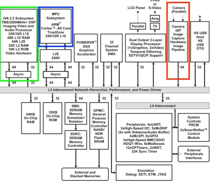
[image:9.595.90.517.294.661.2]The one used for this project is an Overo Firestorm-P model featuring a DM3730 processor (Gumstix Inc., 2015; Texas Instruments, 2010). This processor has an ARM Cortex-A8 and several subsystems dedicated to video or audio processing. In figure 2.1 a functional block-diagram overview of the subsystems and peripherals supported by the DM3730 processor is shown. The ARM-core is denoted by the blue box.
Figure 2.1:Functional block diagram for DM3730 (Texas Instruments, 2011) annotated to show the com-ponents essential for this project.
2.1.1 ISP
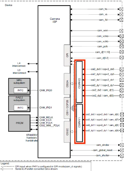
pro-cessing capabilities for RAW imaging sensors. It can be used to directly interface a camera with the processor through a parallel 12-bit input channel or a serial input channel. An overview diagram of the ISP hardware is shown in figure 2.2.
The ISP has a 27-pin connector on the outside that is used to interface with the camera hard-ware. There are two physical layers in the ISP connected to this connector these are marked by the red box in figure 2.2.
Each physical layer can interact with one camera. Therefore, it is possible to connect two cam-eras to the Gumstix ISP simultaneously. This is restricted to two serial camcam-eras or one serial and one parallel camera only, because a parallel camera needs 17 out of the 27 connections to interface with the Gumstix.
Internally the ISP has three receivers that are MIPI compliant (MIPI alliance, 2014). Two of the receivers are compatible with the MIPI D-PHY CSI2 standard and a third CCP2B (compact camera port) is MIPI CSI1 compliant.
The MIPI standard defines hardware and software protocols that dictate how, for example, a camera can be interfaced with a processor.
The ISP also features various internal processing functions. The most important are the pre-viewer and the resizer. The prepre-viewer is capable of formatting an incoming RAW image to a specified image format and the resizer can, as the name implies, resize the images to a speci-fied resolution.
The use of these functions can be defined in software on the Linux platform.
2.1.2 RaMstix
At the Robotics and Mechatronics chair the Gumstix is used in combination with an FPGA for expanded I/O capabilities.
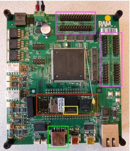
To this end a custom baseboard was created in-house consisting of a PCB with an Altera FPGA, buffered I/O channels, dedicated ADC/DAC, CAN, etc. The PCB is also host to a Gumstix with networking options and USB on dedicated connectors. This baseboard is called the RaMstix (Schwirtz, 2014). In figure 2.3 the RaMstix board is shown with colored boxes indicating the Gumstix (red), the ISP connection (yellow), the USB connection (green) and the FPGA connec-tions (purple).
GPMC
Communication between the Gumstix and the FPGA on the RaMstix baseboard is made possi-ble through a General Purpose Memory Controller bus (GPMC). This bus has a 16-bit wide data channel and a 10-bit address channel. Along with a clock and several status lines it can transfer data between the Gumstix and the FPGA.
2.1.3 Accelerators
Another feature of the Gumstix is its on-chip Digital Signal Processor (DSP). This core is spe-cialized in parallel processing of video and audio. It can be used as a hardware accelerator to encode or decode images retrieved from a camera source. It is connected to the ARM-core through an interconnect and can be accessed from the ARM-core by use of an Inter Processor Communication protocol (IPC). The DSP is denoted in figure 2.1 by the green box.
Figure 2.3: RaMstix board with colored boxes indicating the Gumstix (red) and the possible camera connections
2.2 Cameras
In this design project three different cameras are used: A Logitech C250 USB webcam (Logitech, 2009), the Caspa camera (Gumstix Inc., 2016) and the Omnivision OV7670 (OmniVision, 2006). An overview of these cameras and their specifications is shown in table 2.1.
2.2.1 Logitech C250
Name Connection Resolution max frame rate Output format
Logitech C250 USB 2.0 640x480 30 fps MJPG or YUYV
Caspa camera 27-pin ISP 752x480 60 fps RAW 10-bit Bayer
[image:13.595.86.545.79.139.2]Omnivision OV7670 18-pin ISP compatible 640x480 30 fps RGB or YUYV
Table 2.1:Specification of the chosen cameras
the MJPG or YUYV format before being sent to the Gumstix. There is also no possibility to obtain unformatted images from this camera.
2.2.2 Caspa camera
The Caspa camera is chosen because it is sold by Gumstix Inc. and is directly compatible with the Gumstix being used in the ESL course. The actual camera sensor on the board is an Aptina (ON Semiconductor) MT9V032 CMOS sensor (ON Semiconductor, 2015).
Images generated by the image sensor are unformatted. This means RAW 10-bit Bayer values are sent to the Gumstix. Bayer values represent light intensity and are sorted into colors. The Gumstix has to evaluate these values to generate a formatted image that can be used for further processing.
The connection to the ISP contains an I2C bus to control the camera setup and a 10-bit wide data bus to transfer the image data.
2.2.3 OV7670 camera
The Omnivision OV7670 camera is chosen because it has an internal DSP. Just like the USB webcam it can produce formatted images in either RGB or YUYV format. This means that no formatting has to be done on the Gumstix itself.
The camera is readily available, cheap and a popular choice among electronics-enthusiasts. This also means the camera is well documented and examples of how to use it are available. The camera module has an 18-pin connector that is used for interfacing with other hardware. These connections include an I2C bus to control the camera setup and the image data can be retrieved over an 8-bit wide data bus. It is compatible with the ISP, but an adapter board is needed to convert the 18-pin header to a 27-pin flex cable.
2.3 Software
The software used for this project consists of a Linux distribution running on the Gumstix with various programs needed to sample the camera data and perform operations on the retrieved data. Also several profiling tools are needed to ascertain the performance of different camera setups.
2.3.1 Yocto
The Yocto project is an open source tool used to build custom Linux distributions for embedded systems (Yocto Project, 2010).
Gumstix Inc. has made available a set of meta-layers for their Gumstix Computer-On-Modules. These layers provide hardware specific drivers and image templates that can be used in the Yocto Project to build a Linux distribution tailored to the Gumstix Overo.
Poky is currently on build number 1.8 also called Fido. This distribution utilizes the Linux 3.18 kernel. This build has been extended with the Gumstix meta-layers that include drivers for the camera ISP subsystem.
A detailed explanation of how to create a bootable Yocto distribution can be found in Appendix A.
2.3.2 Software tools
Besides the Linux distribution a number of other software tools are used. Most important are OpenCV and the profiling tools.
OpenCV
OpenCV (Open Source Computer Vision Library) is an open source computer vision and ma-chine learning software library (Bradski, 2000). It is written in C++ and optimized towards real-time operation. The library has a lot of built-in functionality for retrieving image sensor data and especially processing it.
GStreamer
GStreamer is a library used to setup a media pipeline (GStreamer, 2012). It can connect video/audio devices with several filters/codecs and outputs in a flexible way using a command-line interface or through C-programs. It is used in this project to create a pipecommand-line from the camera source to for example a filesink to store images or video data.
Media-ctl
Media-ctl is a command line tool that is used to setup the ISP functionality. This tool allows to enumerate media entities and their pads and generate links between these pads. It is a part of the V4l-utils package from LinuxTV (LinuxTV, 2015). The media entities are the hardware blocks representing the imaging sensor, the receivers, a preview element, resizer and more. The pads are the in- and outputs of the hardware blocks.
These media entities can be linked to form a hardware pipeline for the imaging sensor.
A hardware pipeline can be defined to, for example, grab an image from the camera, format it using the previewer, resize it to a specified resolution and then put it in memory.
Time
Time is a default Linux program that is used to record the time a process takes to execute. The elapsed real time, CPU-seconds spent in user mode and CPU-seconds spent in kernel mode are all recorded separately and can be used to calculate the percentage of the CPU that the process got. A ‘CPU second’ is a second’s worth of CPU cycles running a process or thread. The formula for calculating the CPU load percentage is:
CPU load=CPU-seconds User modeElapsed real time+CPU-seconds Kernel mode
The peak memory usage is also recorded along with other data that is not relevant for its use in this project.
Perf
NMON
NMON is a performance monitor for Linux (Griffiths, 2003). It can output important perfor-mance information on screen, or save it to a comma separated file for further analysis. To per-form this analysis several extra tools are available for creating graphs from the acquired data.
2.3.3 FPGA programming
3 Analysis and feasibility
In this chapter the analysis is made of the problem-statement and possible solutions using a design space exploration.
3.1 Introduction
The problem being faced is the lack of vision systems with regard to the setup used at the Em-bedded System Laboratory course.
This setup currently consists of either a RaMstix with Gumstix or the combination of a Gumstix with the Altera DE0 Nano board. These platforms are connected to the JIWY setup. The USB webcam is connected to the Gumstix and the encoders and motor drivers are connected to the FPGA board.
As is described in Chapter 1 the focus of this project is on the vision subsystem. The acquisi-tion of the images is researched and implemented until the stage where a formatted image is obtained.
A formatted image is defined as an image formatted in an appropriate color-space. The RGB or YUYV color-spaces are used, because they lend themselves well for further processing.
Currently retrieving images through the USB webcam is the only option for the ESL course. There are multiple possibilities to acquire an image and the formatting of the image can be done in multiple places. Each of these possible solutions of acquiring and formatting an image will be referred to as a ‘path’ throughout this chapter.
The design space exploration detailed below will give an overview of the possible paths fol-lowed by a section listing the prioritized requirements that are used for the design and imple-mentation.
3.2 Design space exploration
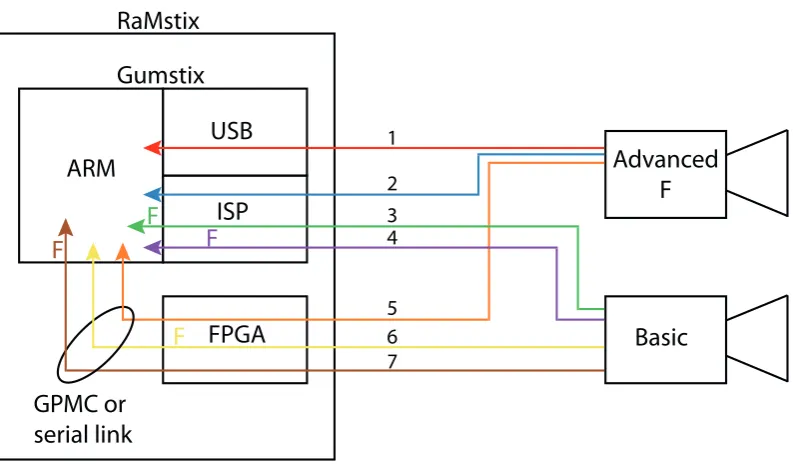
Using the available hardware there are multiple possibilities to interface a camera to the Gum-stix. An overview of the possibilities, indicated by colored paths, is shown in figure 3.1.
In the figure two cameras are shown and three possible interfaces to the ARM-core. The for-matting of the images can be done in either the camera, the interface, or the ARM-core itself. There is also a possibility to speed up the formatting by using the DSP built-in to the Gum-stix. Combining these three things seven paths can be formed through which an image can be retrieved and formatted.
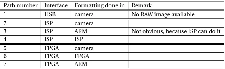
These paths are further specified in table 3.1.
Path number Interface Formatting done in Remark
1 USB camera No RAW image available
2 ISP camera
3 ISP ARM Not obvious, because ISP can do it
4 ISP ISP
5 FPGA camera
6 FPGA FPGA
[image:16.595.89.482.608.730.2]7 FPGA ARM
Table 3.1:List of the available paths
ARM
ISP
FPGA
GPMC or
serial link
USB
Basic
Advanced
F
1 2 3 4 5 6 7Gumstix
RaMstix
F
F
F
F
Figure 3.1:Overview of the different paths to interface a camera. ‘F’ denotes where the formatting is done in case of the ‘basic’ camera.
3.2.1 Interface possibilities
There are three interface options. Cameras can either be interfaced through the USB, ISP or FPGA.
The USB connection on the Gumstix supports the USB 2.0 protocol and as was mentioned before this is currently used in the ESL course.
The dedicated camera ISP on the Gumstix is a logical next-step to use for image acquisition. It consists of a physical interface and an internal structure that can process the RAW data as is explained in Section 2.1.1.
The third interface possibility is using the FPGA to acquire image data. There are two FPGA’s that can be used in this project. The FPGA on the RaMstix and the Altera DE0 Nano board. The difference lies in the connection between the FPGA and the Gumstix. The DE0 Nano board uses a serial connection and the RaMstix a GPMC bus. A comparison between the two is made below.
The RaMstix FPGA has plenty of pins to interface with one of the parallel cameras and with VHDL the functionality of the FPGA can be flexibly defined. It is connected through the GPMC bus that can transfer data 16 bits at a time. Performing a read and write action is clocked at a speed of 280kHz. This amounts to roughly 1 MB/s.
The Altera DE0 Nano FPGA board also has enough pins to interface with a parallel camera. However, the connection between the FPGA and the Gumstix is currently a serial line. The serial line has to transfer data one bit at a time and at a baudrate of 115200 this amounts to roughly 11 KB/s.
To illustrate the data rate generated by the cameras the following calculation is done.
Consider a frame of 160x120 pixels. This is of QQVGA quality and relatively small. Using the RGB565 format for this image results in a data size of 2 bytes per pixel. This equals 160§120§2= 38.400 bytes per frame.
but the serial connection cannot handle this. The serial connection as explained above can only handle 2% of this data bandwidth.
For this reason the project only deals with the FPGA on the RaMstix board and not the DE0 Nano board regarding the camera interface.
3.2.2 Camera types
Two types of cameras are used in this project. These are cameras that output unformatted images and cameras that can generate formatted images. The first type will be called the ‘basic’ camera throughout this report and the second will be referred to as the ‘advanced’ camera.
• Basic camera: generates unformatted images.
• Advanced camera: formatting is done on the camera and generates formatted images.
When using the ‘basic’ camera formatting has to be done either in the interface or on the ARM-core. This is explained in Section 3.2.3.
There are many different cameras that can be used with the Gumstix ISP connection. However, there are two requirements that have to be met:
• The camera needs to comply with the MIPI standards so it can be connected to the ISP.
• There has to be an appropriate Linux driver for the camera so it shows up as a media device and can be used as input device.
With regard to the ISP requirements set and the need for a ‘basic’ as well as an ‘advanced’ era the following three cameras are chosen for this project: The Logitech C250, the Caspa cam-era and the Omnivision OV7670.
Gumstix Inc. has made available a camera board called the Caspa as is explained in Section 2.2. It connects to the ISP interface and fulfills both requirements mentioned above. Also because it is developed by Gumstix Inc. itself, it is an excellent candidate.
The Caspa camera is a ‘basic’ camera and can only generate unformatted frames. Therefore, the formatting still has to be done. This can either be done in the ISP or on the ARM-core as was mentioned.
The OV7670, as explained in Section 2.2, has an internal DSP that is used for formatting images. This ‘advanced’ camera can be used to reduce the resource usage of the Gumstix.
The Logitech C250 is a USB camera that interfaces with the Gumstix using the USB 2.0 protocol. This camera also generates formatted images and can be classified as an ‘advanced’ camera.
3.2.3 Formatting
The images generated by the camera still need to be formatted to be usable. This can be done in five places:
• On the camera itself.
• In the ISP.
• In the FPGA.
• Using the DSP.
When the formatting is done in the ISP this uses resources of the Gumstix processor, because the ISP is a part of it. The ARM-core has to manage the data transfers between the internal ISP elements and the transfer between the ISP and the core itself. This means the ARM-core is resources are also used. These resources are the processor load and the memory usage. To decrease the load on the processor the built-in DSP is available for hardware acceleration. However, from initial research it was decided not to use the DSP. The drivers that are needed to operate the DSP are provided by Texas Instruments, but they have not updated these drivers for years. The DM3730 has been superseded by a new line of processors and therefore, TI decided to deprecate the support for this processor.
Using the FPGA for formatting is a flexible option, but requires writing the formatting conver-sion in VHDL which is a cumbersome process.
On the ARM-core the formatting consists of reading in the RAW image data in OpenCV and using a conversion function from the OpenCV library to format it to for example RGB.
3.2.4 Overview
To summarize, there are two types of cameras: ‘basic’ and ‘advanced’. These can interface through three different connections to the Gumstix: USB, ISP, or FPGA. Finally there are five different options for the formatting: on the camera, in the ISP or FPGA, or on the Gumstix in either the ARM-core or the DSP.
Combining the cameras and interfaces results in the paths shown in figure 3.1. As can be seen there are seven paths from either the ‘basic’ camera or the ‘advanced’ camera through the dif-ferent connections to the Gumstix.
As denoted in the remarks of table 3.1 the USB interface only has one path associated with it. This is because the USB camera that is used is an ‘advanced’ camera and no ‘basic’ mode is available. When using the ISP or the FPGA either the ‘basic’ or an ‘advanced’ camera can be used.
There is some overlap between the paths shown in figure 3.1. Therefore, it is not necessary to implement every single path to test all the possibilities.
The paths numbered 1, 3, and 4 are implemented. Even though path 3 is not an obvious choice when implementing this system in a real-life situation it is the easiest to implement to test the formatting on the ARM-core. The ISP is easy to configure and writing extra VHDL for the FPGA is more cumbersome.
3.2.5 Stereo vision
The paths described above are not limited to single cameras. It is also possible to create a stereo-vision setup. The ISP is equipped to handle two pixel-streams, but as explained in Sec-tion 2.1.1 this can only be done with either two serial cameras or a serial and a parallel camera. There are serial cameras available, but creating a stereo-vision setup using the ISP is not done for the following reasons:
• If two serial cameras are used they both need a different I2C address, because they share the I2C bus that is used for setting up the cameras. Using the same cameras is therefore not an option and complicates the stereo-vision setup.
• Any stereo-vision setup using the ISP requires the design of a custom PCB to be able to connect two different cameras to the ISP connector. It is chosen not to do this due to time constraints on the project.
pixel-I/O pins to interface with two cameras. A separate I2C can be implemented for either camera. This means two identical cameras can be used.
To test the stereo-vision setup, path 5 is implemented in duplex to interface the cameras. Paths number 6 and 7 can also be used, but these are not implemented because using the advanced camera is easier than implementing the formatting in either the FPGA or on the ARM-core.
3.3 Next steps
Based on the design space exploration and the choices made, several requirements are made that are used in the design and implementation. These requirements are for the work to be done and not for a final product based on this project. The requirements are prioritized using the MoSCoW method.
Requirement 1:An image must be retrieved through the either of the three interfaces.
Requirement 2:The resulting image must be formatted.
Requirement 3:A path must be implemented where the formatting is done in the camera.
Requirement 4:A path must be implemented where the formatting is done in the ISP.
Requirement 5:A path must be implemented where the formatting is done in the ARM-core.
Requirement 6:A path should be implemented where the formatting is done in the FPGA.
Requirement 7:The resource usage for implemented paths must be measured.
Requirement 8:Two sensors could be used in a stereoscopic setup.
Requirement 9:Hardware acceleration using the DSP/NEON won’t be implemented.
These requirements cover all the possible interfaces and all the possible places to do the for-matting.
3.4 Conclusion
As shown in the design space exploration, Section 3.2, There are three different interfaces to connect a camera to the Gumstix. These are the USB connection, the ISP, or through the FPGA on-board the RaMstix.
There are also five possible places to do the formatting of the image: on the camera, in the ISP, the FPGA, using the DSP, or on the ARM-core itself.
Using a combination of the cameras, interfaces and formatting possibilities results in seven possible paths to obtain a formatted image that can be used for further processing.
Four of these paths are implemented to meet all the requirements set in Section 3.3. These are paths 1, 3, 4 and 5. The last path is used to implement stereo vision.
4 Design and implementation
The paths that are implemented are path number 1, 3, 4 and 5. As is mentioned in Chapter 3 the last path will be used for the stereo-vision setup. The design of each of these paths is detailed in its own section. Path number 5 is split into a section detailing the implementation using a single camera and a section detailing the design of the stereo-vision setup.
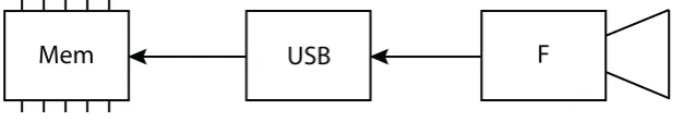
An overview of all the paths that are implemented is shown in figure 4.1. The ‘F’ again denotes where the formatting is done and the dashed lines separate the different parts of the pipelines.
Mem USB F
Mem Preview CCDC
F Resize
Mem CCDC
F
Mem FPGA F
ARM-core Interface Camera (+ processing)
Path 1
Path 3
Path 4
[image:21.595.87.517.221.556.2]Path 5
Figure 4.1:An overview of the implemented paths
The basic setup that is used for all the designs consists of a RaMstix board with the software as is defined in Section 2.3. The goal of each design is to implement the path from the camera to a usable video device in the Linux environment running on the Gumstix. Each of the paths is explained into detail in the sections below.
4.1 Path 1: USB advanced camera
This section describes the design of the first path using a USB webcam where the formatting is done in the camera. This is the path that is currently used at the ESL course. An overview of this path is shown in figure 4.2.
Mem
USB
F
Figure 4.2:Path 1: USB with the advanced camera
With the OpenCV software this video device can be used to retrieve frames and perform further processing when necessary.
4.2 Path 3: ISP basic camera formatting in ARM
This section details the design and implementation of the setup using the Caspa camera con-nected to the Gumstix through the ISP where the formatting of the image is done in software on the ARM-core. An overview of this path is shown in figure 4.3.
Mem
CCDC
F
ISP
Figure 4.3:Path 3: ISP with the basic camera and formatting in the ARM-core
The steps taken to make the Caspa camera show up as a/dev/videodevice are described below.
4.2.1 Hardware design
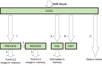
To use the Caspa camera with the ISP, an internal pipeline is created to retrieve the data and then store it in memory. The ISP has an internal structure that is shown in figure 4.4.
It can be seen that there are several possible pipelines from ‘RAW Bayer’ to memory. For this design the pipeline is:
• Camera -> CCDC -> Memory (unformatted)
The CCDC is responsible for accepting unformatted data from the camera as is explained in Section 2.1.1.
Configuring the pipeline of the ISP is done using themedia-ctl program. The command to create the pipeline listed above is shown in listing 4.1.
⌥ ⌅
1 media°c t l °r °l ’"mt9v032 2°005c":0°>"OMAP3 ISP CCDC": 0 [ 1 ] , 2 "OMAP3 ISP CCDC":1°>"OMAP3 ISP CCDC output": 0 [ 1 ] ’
3
4 media°c t l °V ’"mt9v032 2°005c": 0 [SGRBG10 752x480 ] , 5 "OMAP3 ISP CCDC": 1 [SGRBG10 752x480 ] ’
⌃ ⇧
Listing 4.1:ISP pipeline: camera straight to memory
[image:22.595.75.500.295.371.2]Figure 4.4:Camera ISP internal pipeline (CompuLab, 2015).
The format of the retrieved image is SGRBG10 which represents 10-bit RAW Bayer. The image still needs formatting before it can be used. This is done in software on the ARM-core.
4.2.2 Software design
When the setup of the pipeline is complete the output of the CCDC will show up as/dev/video2. This video source generates unformatted images that need further processing by the OpenCV software.
The way this is done is by using aVideoCaptureobject from OpenCV and using the built-in functionality to retrieve a frame from the object. OpenCV uses theMat object as the basic image container. When retrieving a frame from theVideoCaptureobject it has to be stored in a Matobject.
The formatting of the RAW image data can be done using thecvtColor()function of OpenCV. It can convert the image contained in theMatobject from SGRBG10 to RGB.
The code snippet shown in listing 4.2 shows how a frame can be retrieved and then formatted using OpenCV.
⌥ ⌅
1 i n t main ( ) { 2
3 VideoCapture camera ( 2 ) ; // open camera on /dev/ video2 4
5 Mat RAW_frame , formatted_frame ; // create empty containers 6 camera >> RAW_frame ; // r e t r i e v e a frame
7 cvtColor (RAW_frame, formatted_frame , CV_BayerBG2RGB) ; // convert the frame from SGRBG10 to RGB
8
9 imwrite (" t e s t . png", formatted_frame ) ; // write frame to image f i l e 10
11 return 0 ; 12 }
ThecvtColor()function outputs the formatted frame in aMatobject and this can be used for further processing.
4.3 Path 4: ISP basic camera formatting in ISP
In this section the design and implementation of the setup using the Caspa camera while for-matting the image in the ISP is detailed. An overview of path 4 is shown in figure 4.5.
Mem Preview CCDC
F Resize
[image:24.595.72.503.173.238.2]ISP
Figure 4.5:Path 4: ISP with the basic camera and formatting in the ISP
4.3.1 Hardware design
As in the previous section this consists of setting up an internal pipeline in the ISP, but this time to retrieve data, format it and then store it in memory. The same structure as shown in figure 4.4 is used, but the pipeline design has changed to:
• Camera -> CCDC -> Preview -> Resizer -> Memory (formatted)
The previewer element does the on-the-fly conversion to a known format and the resizer crops the image to a configured resolution as is explained in Section 2.1.1.
Themedia-ctlcommand shown in listing 4.3 will create the pipeline listed above.
⌥ ⌅
1 media°c t l °r °l ’"mt9v032 2°005c":0°>"OMAP3 ISP CCDC": 0 [ 1 ] , 2 "OMAP3 ISP CCDC":2°>"OMAP3 ISP preview": 0 [ 1 ] ,
3 "OMAP3 ISP preview":1°>"OMAP3 ISP r e s i z e r ": 0 [ 1 ] , 4 "OMAP3 ISP r e s i z e r ":1°>"OMAP3 ISP r e s i z e r output": 0 [ 1 ] ’ 5
6 media°c t l °V ’"mt9v032 2°005c": 0 [SGRBG10 752x480 ] , 7 "OMAP3 ISP CCDC": 2 [SGRBG10 752x480 ] ,
8 "OMAP3 ISP preview": 1 [UYVY 752x480 ] , 9 "OMAP3 ISP r e s i z e r ": 1 [UYVY 640x480 ] ’
⌃ ⇧
Listing 4.3:ISP pipeline: camera to formatting to memory
The first link, on line 1, is from the camera to the CCDC, this is the retrieval of data. The second link, line 2, is from the CCDC to the previewer, here the image is formatted to the UYVY format. The third link, line 3, couples the previewer to the resizer, this changes the image resolution from 752x480 to 640x480. The final link, line 4, from the resizer to the resizer output writes the data to memory.
When the setup of the pipeline is complete the output of the resizer will show up as /de-v/video6. This generates formatted images and can be used by the OpenCV software to grab frames for further processing.
4.4 Path 5: FPGA advanced camera
Mem
FPGA
F
Figure 4.6:Path 5: FPGA with the advanced camera
This path consists of retrieving image data with the FPGA and transferring the formatted image to the Gumstix through the GPMC bus. To accomplish this the design for this path consists of four major components shown in figure 4.7 and listed below:
• An I2C interface to configure the camera.
• A component to retrieve the image data (frame capture).
• Block RAM to store the image (frame buffer).
• A GPMC interface to transfer data to the Gumstix.
These four component are implemented in VHDL on the FPGA. On the Linux side in the Gum-stix the GPMC driver created at RaM is included to interface with the GPMC. To retrieve the image data from the FPGA a custom class is written to communicate with the FPGA through the GPMC bus. It retrieves the image data and puts it in a format that is understood by the OpenCV software.
The image generated by the OV7670 has a resolution of 160x120 pixels with the RGB565 format-ting. This small frame size is chosen, because the resources in the FPGA are limited and storing a frame of this size will use 27% of the storage resources. When implementing stereo vision, as will be explained in the next section, more than half of the storage resources will be used and retrieving a bigger frame is not possible.
The design of the VHDL components and the software to retrieve image data through the GPMC will be discussed in Sections 4.4.1 and 4.4.2.
4.4.1 Hardware design
The FPGA has to perform the task of initializing the camera, retrieving the data and making it available to the Gumstix through the GPMC bus. An overview diagram of the design to ac-complish this is shown in figure 4.7. This design is the realization of the ‘FPGA’ block in figure 4.6.
I2C interface
The Omnivision OV7670 camera needs to be configured with the right settings for it to generate images. The settings that can be configured are the formatting of images by the internal DSP, the resolution of the images and at what speed the camera produces frames. These settings are communicated to the camera through an I2C interface.
Instead of creating the I2C interface from scratch a ready-made solution can be found at eewiki (Larson, 2015). It implements an I2C-master that connects to the camera I2C bus denoted by the SIOC and SIOD lines in figure 4.7. It is chosen, because it is easy to include in the design and there is proper documentation of how it works. A wrapper is written to utilize the I2C-master component and it includes the correct register values to setup the camera.
I2C interface
Register data
Frame capture
GPMC bus
Frame bu
ff
er
OV7670
Camera
Address DataWrite_en
Address
Data
SIOC
SIOD
XCLK
Href Vsync PCLK
Data Gumstix
[image:26.595.76.500.76.313.2]Data/Addr
Figure 4.7:Overview diagram of the hardware design in the FPGA.
Frame capture and storage
The frame capture component takes clock and data inputs from the camera to be able to cap-ture frames that are being streamed. Each frame has a specific timing dictated by the vertical synchronizationVsync, horizontal referenceHref and pixel clockPCLK. The FPGA uses these lines as triggers to identify when to sample the data bus and read in one byte of the frame. Because the RGB565 format is used, one pixel consists of two bytes. These two bytes are con-catenated and written to the frame buffer. The frame buffer is a piece of Block RAM generated using an Altera-provided megafunction. It uses 16-bit registers and can store an entire frame which adds up to 38.400 bytes of RAM. This uses a 15-bit address space.
GPMC bus interface
The GPMC bus interface is derived from the provided examples created at RaM (Schwirtz, 2014). The example has internal registers that can be accessed by the Gumstix driver. These registers are 16-bit wide as is the actual bus. The address bus is 10-bits wide, as is discussed in Section 2.1.2, and therefore the address space is also limited to 10-bits. These internal regis-ters act as a block of RAM, just like the frame buffer, and the Gumstix can access this RAM by addressing the registers.
Because the address space of the GPMC bus is limited to 10-bits and the address space of the frame buffer is 15-bit wide the frame buffer cannot be used as direct replacement of the internal registers. The Gumstix would not be able to access all of the registers in the frame buffer that way. Therefore, the GPMC component is altered to contain a line buffer that fits within the 10-bit address space. This line buffer can hold one horizontal line of the image stored in the frame buffer. The alteration consists of adding extra logic to the GPMC component that can communicate with the frame buffer and retrieve one line of the image to store in the line buffer. Also some extra steps are taken to make sure the communication between the Gumstix and the FPGA includes a transfer protocol.
line, buffers the line and then signals the Gumstix that the line can be retrieved. This simple protocol allows the Gumstix to retrieve frames one line at a time without missing any data.
4.4.2 Software design
On the Gumstix side a kernel driver is used to interface with the GPMC bus. This driver has been implemented before in the RaMstix project and can be used without modification. Exam-ple programs are also available in C and C++ that show how to retrieve 32-bit values from the internal registers of the GPMC implementation on the FPGA (Schwirtz, 2014).
Based on these examples, a Camera class is written in C++. A UML diagram showing the Cam-era class and the required gpmc_driver is shown in figure 4.8. The CamCam-era class takes care of retrieving frames from the FPGA one line at a time while adhering to the established protocol described in the previous section. The gpmc_driver class provides the low level interface with the GPMC bus.
ThegetValue()function from the gpmc_driver returns 32-bit integers that each represent two pixels from the image. Using theconvert_to_bgr()function this can be structured to an array containing the red, green and blue channels of the image.
The Camera class contains a single public functiongrab_frame()that wraps up the whole pro-cess of retrieving a frame from the FPGA, structuring it into the array that can be put into aMat object and returning a pointer to that array.
Using this class, the camera connected to the FPGA can be used to obtain frames for further processing in OpenCV.
Camera
- device : gpmc_driver*
- frame : uint32_t [0..119][0..79] - frame_bgr : uint8_t [0..119][0..479] - convert_to_bgr()
+ Camera(_device : char*) + grab_frame() : uint8_t*
gpmc_driver
- m_fd : int
+ gpmc_driver(device : char*) + ~gpmc_driver()
+ setValue(value : unsigned int, idx : int) + getValue(idx : int) : unsigned long + isValid() : bool
[image:27.595.95.501.391.471.2]0..1 -device
Figure 4.8:UML diagram showing the Camera class and the gpmc_driver
4.5 Path 5: FPGA advanced camera stereo vision
This section describes an extension to the previous path so that it can be used for stereo vision. The stereo-vision setup contains two Omnivision OV7670 advanced cameras. These cameras are connected to the FPGA on the RaMstix and the design of the hard and software is similar to the path detailed in the previous section. An overview of the implementation is shown in figure 4.9.
The cameras are setup to generate an 160x120 pixels image with the RGB565 formatting and both cameras are read simultaneously.
In figure 4.9 it can be seen that there are two external cameras and most components also used in the previous section are now used twice. There are two I2C interfaces, two frame capture components and two frame buffers.
The I2C component is still the same as the one used in the previous section only this time the I2C-master and the register data are shown as one block called I2C interface.
I2C interface
Frame capture
GPMC bus
Frame buffer
OV7670 Camera
Write_en Address Data
SIOC SIOD XCLK Href Vsync PCLK Data
Gumstix Data/Addr
I2C interface
Frame capture Frame buffer
OV7670 Camera
Write_en Address Data
SIOC SIOD XCLK Href Vsync PCLK Data Address
Data
Address
[image:28.595.75.499.76.359.2]Data
Figure 4.9:Overview diagram of the hardware design in the FPGA for stereo vision.
the Gumstix can grab both frames at the same time. The same Camera class that is discussed in Section 4.4.2 is used. The resulting image in software has a resolution of 320x120 pixels and is made available as an array object that can directly be used by the OpenCV software.
5 Measurements and results
The implemented paths as described in Chapter 4 are tested to determine the impact each path has on the performance of the Gumstix.
The performance of the Gumstix is related to the processor load and the memory usage of a cer-tain path. These resources are also used by other programs running on the Gumstix. Therefore, less resource usage leaves more room for other programs like the image processing.
In the sections below the basic setup and the measurements are explained followed by the measurements done for the different paths in separate sections.
5.1 Basic test setup and measurements
The test setup consists of the RaMstix with the Yocto generated Linux-image as is described in Appendix A.
The hardware of the test setup consists of the Caspa camera connected to the ISP connector as is shown in figure 5.1 denoted with the yellow box.
The Logitech C250 camera is connected to the USB port of the RaMstix denoted by the green box in figure 5.1 and two OV7670 cameras are connected to the FPGA denoted by the purple box. Depending on the setup of the FPGA either one camera can be used to test path 5, or both cameras can be used to test the stereo-vision setup with path 5. The pin-layout and instructions for initializing the FPGA setup are described in Appendix B.
To be able to compare the obtained results from paths 1 and 4 with path 5, the resolution of the retrieved images is set to 160x120 pixels. This is because path 5 is limited to using this resolu-tion, because the storage in the FPGA is limited as is explained in Section 4.4. Measurements with the default resolution of 640x480 pixels are also done with path 1 and 4 to determine their performance.
5.1.1 Measurements
Two different measurements are performed to test different aspects of the cameras. These test are the following:
• Compare test
• Load test
The compare test is used to compare the different paths with each other. It uses an OpenCV program to retrieve a set number of frames. The time that this process takes is recorded to-gether with the processor load and peak memory usage.
The load test is done to determine the resource usage of a single path without any overhead. To this end GStreamer is used to eliminate the overhead created by OpenCV.
Figure 5.1:RaMstix with connected cameras denoted by the colored boxes.
This means that the load test can only be performed on the paths that result in a/dev/video
device and not for path 5 using the FPGA and GPMC bus.
Compare test
To perform the compare test measurement an OpenCV program is written that retrieves 100 frames through each of the paths and the time that this process takes is recorded. The results of this test show the difference in speed and processor load each path has.
number of CPU-seconds the process spent in kernel mode plus the number of CPU-seconds spent in user mode divided by the elapsed real time the process took to execute as is explained in Section 2.3.2.
The essentials of the OpenCV program that is used to retrieve the 100 frames through each path are shown in listing 5.1.
⌥ ⌅
1 #define number_of_frames 100 2
3 i n t main ( ) { 4
5 VideoCapture cam(X) ; // open camera on /dev/videoX 6
7 Mat frame ; // create an empty image container 8
9 for(i n t i =o ; i <number_of_frames ; i ++) { // repeat 100 times 10 cam >> frame ; // r e t r i e v e a frame from the camera 11 }
12
13 return 0 ; 14 }
⌃ ⇧
Listing 5.1:OpenCV code to retrieve 100 frames
For path number 5 the OpenCV program is slightly altered to communicate with the Camera class instead of theVideoCaptureobject for image retrieval.
Because the tests are run on a Linux system taking a single measurement of a 100 frames is not an accurate depiction of the speed of the path. There are other processes running simul-taneously on the system that also require resources and can interfere with the measurement. Therefore, this measurement is automated with a script that performs the test a 100 times to generate more data points. The results of each separate test are stored in a text file. These are then used to calculate an average time that is needed to retrieve a 100 frames, the average processor load and the average memory usage.
Load test
To perform the load test a GStreamer pipeline is created that sets the camera to a fixed frame rate of 30 frames per second. The output of the pipeline is written to afakesinkthat effectively discards the data. By using afakesink, a better estimation of the resources used by the camera itself can be made. When writing the output of the pipeline to a file some of the measured resource usage is due to accessing and writing to the file system. The results are again obtained by using the program ‘time’ and as mentioned before this test can only be run on paths that result in a/dev/videodevice.
To setup this pipeline the command shown in listing 5.2 is used.
⌥ ⌅
1 gst°launch°1.0 °e v4l2src device =/dev/videoX num°buffers =100 ! video /x°raw ,
framerate =30/1 ! fakesink
⌃ ⇧
Listing 5.2:GStreamer pipeline with fixed frame rate
The tests are automated again to obtain a 100 measurements of every implemented path to account for the variation in used resources that is the result of running the process on a Linux system.
The processor load and memory usage are recorded to text files and again averaged to obtain an approximation of the impact each path has on the Linux system.
cameras to be ready to stream data. The duration of this paused state is random and therefore the otherwise recorded time is not representative.
5.2 Path 1: USB advance camera
Path 1 uses the Logitech C250 camera connected to the USB port of the RaMstix where format-ting of the images is done in the camera. Images travel the path shown in figure 4.2. Both the compare test and the load test are run for this setup and the results are discussed below. All the measurement results of the compare test and load test, which are each repeated 100 times, are shown only in this section to show the results can fluctuate. The following sec-tions detailing the other implemented paths only show the resulting averages instead of all the graphs.
5.2.1 Compare test path 1
The results of the compare test using path 1 with a resolution of 640x480 pixels are shown in figure 5.2.
0 20 40 60 80
0 10 20 30 40 Measurement number E lapsed time (s)
Compare test: Time measurement path 1
0 20 40 60 80
60 80 100 Measurement number M emor y u sed (M B)
Compare test: Memory usage path 1
0 20 40 60 80
0 20 40 60 80 100 Measurement number CPU load (%)
[image:32.595.78.480.298.673.2]Compare test: CPU load path 1
Figure 5.2:Compare test results for path 1
As can be seen the measured elapsed time, memory usage and CPU load are altering slightly between the measurements, but there are no large deviations. The averages and standard de-viations of the measurements are:
Compare test Load test (640x480) (160x120) (640x480) (160x120) Elapsed time (s) 6,71 4,32
[image:33.595.132.468.81.152.2]CPU load (%) 47,14 7,97 3,22 3,01 Memory usage (MB) 86,48 59,26 28,72 24,84
Table 5.1:Measurement results path 1
• Memory usage: 86,48 MB æ=0.447
• CPU load: 47,14% æ=0.569
5.2.2 Load test path 1
The results of the load test with a resolution of 640x480 are shown in figure 5.3. Again there are
0 20 40 60 80 0 20 40 60 80 100 Measurement number CPU lo ad (%)
Load test: CPU load path 1
0 20 40 60 80 0 20 40 Measurement number M emor y u sed (M B)
[image:33.595.95.492.275.455.2]Load test: Memory usage path 1
Figure 5.3:Load test results for path 1
no large deviations, but now it can be seen that the load on the CPU is significantly lower when creating a direct pipeline with GStreamer instead of retrieving frames through OpenCV. It can be seen that the memory usage is also lower. This is due to the use of GStreamer and writing to afakesink, which uses no extra memory to buffer the resulting image as opposed to OpenCV. The averages and standard deviation of the measurements are:
• CPU load: 3,22% æ=0.416
• Memory usage: 28,72 MB æ=0.201
The compare test and load test are also run with the lower resolution of 160x120 pixels to be able to compare the results with path 5. The averages of these measurements are shown in table 5.1 that shows an overview of all the results obtained for path 1.
5.3 Path 4: ISP basic camera formatting in ISP
Path 4 uses the Caspa camera connected to the ISP interface and the formatting of the image is done in the ISP. Images travel the path shown in figure 4.5. Both the compare test and load test are run using this path and the averages of the results for path 4 are listed in table 5.2.
5.4 Path 5: FPGA advanced camera
format-Compare test Load test (640x480) (160x120) (640x480) (160x120)
Elapsed time (s) 37,92 3,13
CPU load (%) 49 48,61 37,42 12,98
[image:34.595.114.452.79.151.2]Memory usage (MB) 86,43 59,60 33,36 25,16
Table 5.2:Measurement results path 4
run on this path, because the camera is interfaced through the FPGA and does not show up as a/dev/videodevice as is explained in Section 5.1.1. The test is only run on the lower resolution, because the FPGA memory is limited and cannot handle a larger image size as is explained in Section 4.4.
The averages of the compare test for path 5 are shown in table 5.3.
Compare test (160x120) Elapsed time (s) 2,91
CPU load (%) 49
Memory usage (MB) 57,70
Table 5.3:Measurement results path 5
5.5 Path 5: FPGA advanced camera stereo vision
This path is similar to the path in the previous section, but now two cameras are used simulta-neously.
The averages of the compare test for path 5 with stereo vision are shown in table 5.4.
Compare test (320x120) Elapsed time (s) 5,36
CPU load (%) 50,48
Memory usage (MB) 57,72
Table 5.4:Measurement results path 5 stereo vision
5.6 Comparison
In this section the results of the compare test and load test for different paths are compared and the results explained. Each comparison will be made in its own subsection.
5.6.1 Compare test at low resolution
The results of the compare tests run with the lower resolution of 160x120 pixels are combined in figure 5.4 to clearly show the differences between the paths in terms of speed, CPU load and memory usage.
path 1 path 4 path 5 path 5 ster
eo 0 2 4 6 4.32 3.13 2.91 5.36 E lapsed time (s)
Compare test: Time measurement
(a)Time measurement
path 1 path 4 path 5 path 5 ster
eo 0 20 40 60 80 100 7.97
48.61 49 50.48
CPU
load
(%)
Compare test: CPU load
(b)CPU load measurement
path 1 path 4 path 5 path 5 ster
eo 0 20 40 60 80 100
59.26 59.6 57.7 57.72
M emor y u sed (M B)
Compare test: Memory usage
[image:35.595.91.492.84.510.2](c)Memory usage measurement
Figure 5.4:Compare test comparison at low resolution
The time required to retrieve 100 frames through each of the paths is shown in figure 5.4a. It is the lowest for path 5. This is to be expected, because it has the largest bandwidth towards the processor. Images can be retrieved 16 bits at a time. The 4th path comes in second, because it has the second largest bandwidth towards the processor. In path 4 images are retrieved 12 bits at a time. The USB camera in path 1 is slower as is expected, because all the data has to be retrieved serially.
Path 5 using stereo vision is slowest. This is due to the fact that the stereo vision has to retrieve an image twice the size of the images the other paths have to retrieve.
0 1 2 3 4 5 6 0
20 40 60 80 100
(4)
(5)
(1)
(5s)
Elapsed time (s)
CPU
lo
ad
(%)
[image:36.595.129.443.81.277.2]path 1 path 4 path 5 path 5 stereo
Figure 5.5:Scatter plot showing the elapsed time versus the CPU-load for each path
5.6.2 Compare test high resolution
The results of the compare test that is run on path 1 and 4 with an image resolution of 640x480 pixels are shown in figure 5.6.
The memory usage, which is linked to the image size, of the higher-resolution compare test is shown in figure 5.6c. It can be seen that the memory usage is equal for both path 1 and 4, but both are higher than the memory usage at a lower resolution.
The CPU load as shown in figure 5.6b is also equal for all paths. The higher CPU load for path 1, as compared to the compare test at lower resolution, is most likely due to the higher image resolution used and the memory copy function that is used in OpenCV. The images are still acquired using the DMA of the USB hardware, but also have to be transfered to another piece of memory by the OpenCV software.
The time to retrieve 100 frames through either path 1 or 4 is shown in figure 5.6a and is sub-stantially higher for path 4. Even though the bandwidth from the camera to the processor is higher, the memory copy function most likely slows down the process of retrieving larger frames through path 4.
5.6.3 Load test
The load test is performed for path 1 and 4 and the results from the measurements are com-pared in figure 5.7.
With the fixed frame rate and afakesinkto deposit the retrieved images, the memory usage as shown in figure 5.7b is lower in comparison with the compare test on the same resolution. The reason for this is that the frame is not copied to a buffer allocated by OpenCV, but is discarded directly after retrieval.
The CPU load needed for path 1 as show in figure 5.7a is very low. This is, as is explained before, due to the DMA present in the USB hardware and when streaming to afakesink the memory copy function is not used at all. The CPU load for path 4 is lower in comparison with the compare test, but still has a considerable impact on the Gumstix processor.
5.6.4 Conclusion
path 1 path 4 0 20 40 6.71 37.92 E lapsed time (s)
Compare test: Time measurement
(a)Time measurement
path 1 path 4 0 20 40 60 80 100 47.14 49 CPU load (%)
Compare test: CPU load
(b)CPU load measurement
path 1 path 4 0 20 40 60 80 100 86.48 86.43 M emor y u sed (M B)
Compare test: Memory usage
[image:37.595.90.491.77.496.2](c)Memory usage measurement
Figure 5.6:Compare test comparison at high resolution
path 1 path 4 0 20 40 60 80 100 3.22 37.42 CPU lo ad (%)
Load test: CPU load
(a)CPU load measurement
path 1 path 4 0 20 40 28.72 33.36 M emor y u sed (M B)
Load test: Memory usage
(b)Memory usage measurement
[image:37.595.101.489.521.722.2]program. This is due to the DMA that is present in the USB hardware. Path 4 is a good alterna-tive when the same higher resolution of 640x480 pixels is needed, but requires more resources to operate.
6 Conclusions and recommendations
The goals and conclusions from previous chapters are summarized in this final chapter. Also several recommendation for future work are given.
6.1 Conclusions
The goal of this project is to explore the paths that can be used to connect a camera to the Gum-stix with the purpose of obtaining a formatted image that can be used for further processing. To this end a design space exploration is done with the available hardware for the ESL course and extra cameras. Based on the design space exploration the RaMstix in combination with the Gumstix and three different cameras are chosen to be used.
Three different interfaces can be used to connect a camera to the Gumstix. These are the USB connection, the ISP, or through the FPGA on-board the RaMstix.
The three cameras that are chosen to be used with the interfaces are the Caspa camera using the ISP connection, the Logitech C250 with a USB connection and the Omnivision OV7670 that can be interfaced through the FPGA.
The formatting of the image can be done in five different places: on the camera itself, in the ISP, using the FPGA, using the DSP on the Gumstix, or on the ARM-core of the Gumstix itself. Of these options the DSP is not usable, because of outdated and deprecated drivers.
When combining the interfaces and formatting options seven possible paths to obtain a for-matted image can be made. These paths are also not limited to single cameras, but some of them can be used to create a stereo-vision setup. Four of these paths have been implemented and tested including a stereo-vision setup.
The design and implementation resulted in a working setup where images made by the Caspa camera can be retrieved through the ISP and images made by the Omnivision OV7670 camera can be retrieved through the FPGA in either a mono, or stereo-vision setup.
The measurements performed on the implemented paths show that the USB connected Log-itech C250 camera uses the least resources of the Gumstix. This is due to the DMA capabilities of the USB hardware that are not enabled for the other camera options. When an implemen-tation is required that has restraints on the dimensions the Caspa camera connected through the ISP is a good alternative. It requires no extension board like the RaMstix to add an external USB connection, but can be directly interfaced to the ISP that is present on the Gumstix itself. It does require more resources to operate than the USB connected camera.
When a lower resolution vision system is sufficient the FPGA connected OV7670 camera is a fast and flexible option due to the high bandwidth of the interface. The path using the FPGA to interface cameras also allows for a stereo-vision setup. It is limited in resolution, because there are limited storage resources in the FPGA.
6.1.1 Embedded System Laboratory
These vision systems can also be used in other setups in the lab and also a stereo-vision system based on the OV7670 cameras and the RaMstix is now available.
6.2 Recommendations
The different possibilities of interfacing cameras to the Gumstix have been investigated and are partly implemented. It has been made possible to use the ISP-connected camera and the FPGA-connected camera with the Gumstix, but there are still several improvements to be made. For the ESL course the recommendations are to find a different option to physically connect the Caspa camera to the Gumstix. In this project a flex-cable is used that is short and delicate. A more robust solution would allow for the Caspa camera to be built into the moving part of the JIWY setup.
The ESL manual should be updated with new information about how to connect the different camera options and how to use them from the Linux environment. The appendices of this report provide information about how to accomplish this. Several assignments can be added that deal with the setup of the hardware pipelines using ‘media-ctl’, or how to extract data from the OV7670 camera using the FPGA.
For research purposes the recommendations are to enable the DMA support for the ISP con-nection. This will lower the resource usage of the ISP-connected camera and make it even more suitable as a vision system.
A Creating the Yocto image
This appendix explains how to recreate the software setup that is used in the report for inter-facing with the Caspa camera.
A.1 Basic Yocto setup
The first step is to follow the instructions on https://github.com/gumstix/yocto-manifest until step 4. This explains the basic setup of obtaining a Yocto build and adding the meta-gumstix layers. As was explained in chapter 2.3.1 these layers provide the necessary software for the Gumstix specific hardware.
There are some extra instructions that need to be followed to include the correct programs used in this report. The following steps ensure that the profiling tools and other software are included.
After step 4 of the instructions from the yocto-manifest do the following: Edit the yocto/build/-conf/local.conffile to make sure the MACHINE variable is set to ‘overo’. Also in that file locate the line that reads ‘EXTRA_IMAGE_FEATURES’ and add the dev-pkgs, tools-sdk and debug-tweaks to that line.
The meta-layers include several basic build targets, but a custom one is made to include the OpenCV software, Gstreamer and other tools. To do this create a new file called ‘gumstix-camera-image.bb’ in the yocto/poky/meta-gumstix-extras/recipes-images/gumstix/ direc-tory.
The contents of the file are as follows:
⌥ ⌅
1 DESCRIPTION = "A Gumstix console image including Gstreamer and OpenCV for computer vision "
2
3 require gumstix°console°image. bb 4
5 IMAGE_INSTALL += " \
6 gstreamer1 . 0 \
7 gstreamer1.0°plugins°base \
8 gstreamer1.0°plugins°good \
9 opencv \
10 perf \
11 "
⌃ ⇧
After this is done return to the main yocto folder and run the following commands:
⌥ ⌅
1 source . / poky/oe°i n i t°build°env 2 bitbake gumstix°camera°image
⌃ ⇧
This process can take a few hours the first time it is run. When the process is finished the Gumstix image is available in theyocto/build/tmp/deploy/imagesfolder.
A.2 Support for driver compilation
The image is now ready to be used with the USB webcam and Caspa camera, but to be able to communicate with the FPGA the GPMC driver has to be compiled and installed. The compila-tion is best done natively on the Gumstix. For this to work the kernel files need to be present. The following steps need to be done to accomplish this:
1. Boot the Gumstix with the previously created micro-SD card. Login with the root ac-count, this has no password. Then change to the/usr/srcfolder and download the kernel archive to the Gumstix using the following command:
⌥ ⌅
1 cd / usr / src
2 wget https : / / github .com/gumstix/ linux / archive /yocto°v3 . 1 8 . y . t a r . gz
⌃ ⇧
2. Unpack and rename the kernel archive using the following commands:
⌥ ⌅
1 t a r xvfz yocto°v3 . 1 8 . y . t a r . gz 2 mv linux°yocto°v3 . 1 8 . y linux
⌃ ⇧
3. Make a symbolic link from the linux folder to the/lib/modules/folder and prepare the kernel:
⌥ ⌅
1 ln °s / usr / src / linux / l i b /modules/3.18.18°custom/ build 2 cd / l i b /modules/3.18.18°custom/ build
3 make mrproper
⌃ ⇧
4. Copy the defconfig file from the yocto build on the host pc to the/usr/src/linuxfolder on the Gumstix. This can be done with for example scp. The file must be renamed to .config after copying. The defconfig file can be found in the yocto/build/tmp/work/overo-poky-linux-gnueabi/linux-gumstix/3.18-r0/folder.
On the host pc run:
⌥ ⌅
1 cd path/ to / yocto / build /tmp/work/over°poky°linux°gnueabi/ linux°gumstix/3.18°r0
/
2 scp defconfig root@gumstixIP°address : / usr / src / linux /
⌃ ⇧
On the Gumstix run:
⌥ ⌅
1 mv / usr / src / linux / defconfig / usr / src / linux / . config
⌃ ⇧
5. Then prepare the kernel modules:
⌥ ⌅
1 cd / l i b /modules/3.18.18°custom/ build 2 make modules_prepare
⌃ ⇧
⌥ ⌅ 1 cd path/ to / yocto / build /tmp/work/overo°poky°linux°gnueabi/ linux°gumstix/3.18°
r0 / linux°overo°standard°build /
2 scp Modules . symvers root@gumstixIP°address : / usr / src / linux /
⌃ ⇧
On the Gumstix run:
⌥ ⌅
1 cd / l i b /modules/3.18.18°custom/ build 2 depmod °a
⌃ ⇧
After completing these steps the Gumstix is ready to build kernel modules.
A.3 GPMC kernel driver
To make use of the GPMC connection to the FPGA a kernel driver is needed that handles the low level communication. The source files for this driver can be found in the RaMstix documenta-tion (Schwirtz, 2014). A few changes have to be made to make sure the right includes are used. To simplify the process the altered driver code can be found in the source files accompanying this report.
To compile the kernel module copy the folderkernel_modulefrom the source files to the Gum-stix by using for example the scp-command again.
On the Gumstix change directories to thekernel_modulefolder and build it:
⌥ ⌅
1 cd kernel_module 2 make
⌃ ⇧
This will result in the file ‘gpmc_fpga.ko’ being generated in thekernel_module/src/directory. This is the compiled kernel driver to communicate with the GPMC.
To use the driver simply add it to the running system with the following command:
⌥ ⌅
1 insmod gpmc_fpga . ko
⌃ ⇧