Design of a novel needle steering manipulator for
minimally invasive guided breast biopsy
E.M. (Evyatar) Bukai
MSc Report
C
e
Prof.dr.ir. S. Stramigioli
Dr.ir. T.J.A. de Vries
Dr. S. Scheggi
Dr. F.J. Siepel
August 2016
038RAM2016
Robotics and Mechatronics
EE-Math-CS
University of Twente
iii
Abstract
Breast cancer is the most common type of cancer worldwide in women. Most types of breast cancer are detected by diagnosis of extracted tissue cells by microscopic analysis. With the in-crease of popularity of Minimally Invasive Surgery (MIS) across the medical field, needle breast biopsy under ultrasound guidance is the procedure of choice to detect and retrieve tissue for histopathologic study. Highly dependent on the skill and experience of the radiologist, various techniques allow for precise lesion targeting and accurate diagnosis of extracted biopsy tissue samples.
A novel parallelogram-based Remote Center of Motion (RCM) mechanism for automated min-imally invasive breast biopsy is proposed in this paper. Allowing for an adjustable work-ing point, the development of this 3 DOF needle steerwork-ing mechatronic system promotes the demonstration of precise and accurate lesion targeting. Guided by an integrated ultrasound probe, this safety driven apparatus sets groundwork towards the development of an FDA ap-proved needle steering manipulator for ultrasound guided breast biopsy.
Preface
This report marks the final step in my life as a Systems&Control student at the University of Twente. I am thankful for all the opportunities I had and the people from the department who supported me and gave great advice for completion of this work.
Evyatar Bukai
v
Contents
Glossary vii
1 Introduction 1
1.1 Problem statement . . . 1
1.2 Report outline . . . 2
2 Overview 3 2.1 Background . . . 3
2.1.1 Ultrasound guided breast biopsy . . . 3
2.1.2 Mechanisms development and principles . . . 4
2.2 State of the Art . . . 5
2.2.1 Minimally invasive intervention . . . 5
2.2.2 Ultrasound guided needle systems . . . 7
2.2.2.1 Pre-operative . . . 7
2.2.2.2 Intra-operative . . . 8
3 Mechanism Design 10 3.1 Problem analysis . . . 10
3.1.1 Requirements . . . 10
3.2 Conceptual design . . . 12
3.2.1 Design Guidelines . . . 12
3.2.1.1 Remote center of motion . . . 13
3.2.1.2 Modified parallelogram-based mechanism . . . 15
3.2.1.3 Ultrasound probe housing . . . 18
3.2.1.4 Fail safety . . . 19
3.3 Detailed design . . . 22
3.3.1 Kinematics . . . 22
3.3.1.1 Forward Kinematics . . . 22
3.3.1.2 Inverse Kinematics . . . 26
3.3.2 Workspace Analysis . . . 27
3.3.2.1 Angle and location of the needle’s insertion point . . . 27
3.3.2.2 Distribution of the breast’s dimensions . . . 28
3.3.2.3 Ultrasound workspace . . . 29
3.3.2.4 Mechanism workspace and size synthesis . . . 29
3.3.3 Statics . . . 31
3.3.4 Computer aided design . . . 31
3.3.4.2 Linear guidance . . . 33
3.3.4.3 Double-parallelogram . . . 35
4 Realization 37 4.1 Fabrication . . . 37
4.1.1 Printing components . . . 37
4.1.2 Actuation and sensing . . . 38
4.1.3 Coupling . . . 39
4.1.3.1 Motor coupling . . . 39
4.1.3.2 Linkage coupling . . . 39
4.2 Set-up . . . 40
5 Evaluation 41 5.1 Needle steering . . . 41
5.1.1 Workspace . . . 41
5.1.2 Accuracy and precision . . . 42
5.1.3 Static and kinetic frictions . . . 44
5.2 Uncertainties . . . 44
5.3 Further aspects . . . 45
6 Conclusion 46 6.1 Future work . . . 47
A Appendix 48 A.1 Coordinates of point B . . . 48
A.2 Loads analysis . . . 49
A.3 Arduino’s pins assignment . . . 51
vii
Glossary
ABS Acrylonitrile Butadiene Styrene
CT Computed Tomography
DC Direct Curent
DOF Degrees Of Freedom
FOV Field Of View
MIS Minimally Invasive Surgery
MRI Magnetic Resonance Imaging
MURAB MRI and Ultrasound Robotic Assisted Biopsy
PWM Pulse Witdh Modulation
RCM Remote Center of Motion
1
1 Introduction
Breast cancer comprises 25% of cancers diagnosed in women, making it the most common fe-male cancer (Ferlay et al., 2015). Currently, it affects approximately 12% of women worldwide, making it the leading cause of cancer deaths in women (McGuire et al., 2015). Following lesion targeting and sample extraction of the affected area of the breast, most types of breast cancer are detected by diagnosis of tissue cells by microscopic analysis.
In the last decades, Minimally Invasive Surgery (MIS) has been the operation of choice when malignant tissue extraction is of need. MIS has gained popularity over conventional open surgeries by offering a safe procedure, quick post-operation recovery and important cost-effectiveness.
The introduction of highly accurate and precise robotic systems in the medical field aims towards an improvement of the procedures’ workflow by assisting the professional with ap-propriate tools and support. As regulations of safety and health in the medical field are exigent and of strict jurisdiction, the design of such systems can be quite challenging to some extent, taking into account crucial aspects such as sterilization, safety, repeatability and precision. It is indispensable to realize that accurate lesion detection is necessary for taking advantage of such systems. Indeed, many image modalities, such as, for example, Ultrasound scans (US), Magnetic Resonance Imaging (MRI) and Compute Tomography (CT), offer the possibility to identify and scan specific regions of interest and are of need for the robotic systems to suitably intervene. Creating a needle path for lesion reach is solely possible if both the intra and extra-corporeal anatomy and tissue composition of the patient to be treated can be investigated.
This research is part of the MRI and Ultrasound Robotic Assisted Biopsy (MURAB) project (MURAB, 2016), a four-year European project, whose ambition is to drastically improve pre-cision and effectiveness of the biopsy gathering for cancer diagnostic operations. By reducing the usage of expensive Magnetic Resonance Imaging (MRI) and simultaneously providing high precision and accuracy during tissue samples targeting, a new workflow is offered to the prac-tice. Guided by a novel MRI-Ultrasound (US) registration, a newly developed needle steering mechanism, similar to the designed manipulator as in this paper, will be attached on a robotic arm for autonomous scan of a target area and optimal volumetric and elastographic data ac-quisition.
1.1 Problem statement
Targeting of lesions inside the breast is greatly dependent on the radiologist. Besides the mul-titude techniques to achieve an extraction of such ensemble, its success is highly dependent of the performance of the professional performing the procedure. Many difficulties could arise from human errors, originating from tremors or labor tiredness, making repetitiveness of such interventions poor.
The focus of this research is to design a mechanism providing precise and accurate lesion targeting. The prototype of a novel steering needle manipulator for minimally invasive guided breast biopsy has as an ultimate goal to improve clinical workflow. This project is part of the European research project MURAB, hence the end effector has the intent to be attachable on a KUKA LWR arm, and allowing for future scanning and biopsy procedures. The development of such a mechatronic system will allow the demonstration of repeated and precise lesion targeting, its achievement and potential in the medical field.
1.2 Report outline
3
2 Overview
In order to build an opinion and critical mind for the development of our mechanism’s design, it is important to examine the faced obstacles that will need to break through, what was pre-viously attempted to do so and the culmination for achieving the most appropriate apparatus for purposes such as ours.
In this chapter, the importance ultrasound guided breast biopsy has reached in our time is firstly discussed. Then, principles leading to tackling the main issues faced in the development of machines for biopsy purposes are reviewed. Finally, an outline of the current state of the art will be carried, by going through existing and previously instigated mechanisms, in order to prepare the ground for the development of a proper and befitting mechanism.
2.1 Background
2.1.1 Ultrasound guided breast biopsy
Several techniques exist for tissue sampling extraction in women’s breast.
Avoiding breast surgical open biopsy is crucial in order to circumvent any complications that may occur, and such procedures can be replaced by practices such as fine needle aspiration biopsy on the patient. This procedure, nevertheless, does not preserve histological architecture of the tissue cells from the extracted sample of tissue or fluid, which is beneficial for accurate case study, as can be found in incisional or core biopsies (Ibrahim et al., 2001).
With the increase in the importance of imaging studies for improvement of breast diseases dia-gnosis and due to the growing desire of further rigorous case studies, breast lesion core needle biopsy is commonly performed using imaging method as guidance. As most breast lesions are sonographically visible, ultrasonography is usually the diagnostic imaging technique of choice.
There are various steps a practitioner needs to consider when performing ultrasound guided core biopsy of breasts. Such practice techniques are usually rigorously described and thor-oughly mimicked, such as in Rocha et al. (2013), in order to obtain a procedure leading to the best results that can be acquired.
Besides its repeatability and being able to reach all areas of the patient’s breast, ultrasound guided core biopsy allows imaging of the needle insertion in real time. The complications arising from such procedure are minimal, and its cost-effectiveness makes it favorable with comparison to surgical biopsy. Already in the year of 1998, the use of ultrasound guided biopsy decreased the cost of diagnosis by more than 50% over the cost of surgical biopsy (Liberman et al., 1998).
In order to resolve and answer to the demand towards improved operation, assistive robotic systems have been developed for needle insertions, guided by ultrasound imaging.
2.1.2 Mechanisms development and principles
Robotic systems have risen as an alternative for performance of tedious and high precision task in a world where human health risk factor is one of the leading cause of demand pull and technological push. The many advantages they offer, and the desire to provide safer and less invasive surgical procedures, led to their involvement in what is defined as minimally invasive surgeries (MIS).
MIS is a surgical operation performed through small incisions. The concept of such procedure is to insert a surgical instrument, such as a needle biopsy, in order to access the suspicious tissue through a small port on the patient’s skin. As stated from (Kuo and Dai, 2009a), MIS has provided a solution for minimization of health risk when surgery is needed, by reducing the risk of infection and recovery time, minimizing bleeding and scarring, as well as shorter time of hospitalization. Hence, it became a popular replacement for traditional surgical procedures in open surgeries.
There are many types of systems allowing for MIS. Depending on the procedure that has to be accomplished, their characteristics differ vastly.
In his overview about MIS robots, (Kuo et al., 2012) puts a great deal about kinematic design considerations of previously developed mechanisms. MIS robots have to manipulate their surgical instruments so that they rotate about a fixed point on the patient’s body and the work-space volume of the manipulator outside of the patient’s body should be such that collision of any sort is avoided.
This has pushed researches into developing mechanisms that accomplish such motion, namely rotating around a fixed rotational center point located at some distance from the mechanism itself. The concept of Remote Center of Motion (RCM) was devised in order to accomplish this required motion (Z. and Z, 2015).
Non-mechanical RCM are possible thanks to the coordinated control of multiple joints for high Degrees Of Freedom (DOF) robots. Their advantage could lie in the changeable pivot point location and increased maneuverability (Taylor and Stoianovici, 2003), as could have been seen from the robot developed by (Dombre et al., 2004) for endoscopy purposes.
Passive RCM mechanisms such as apparatus developed in (Begin et al., 1995) or (Sackier and Wang, 1994), allow the robot to use the incision itself as a fixture, in order to constrain tool motion by leaving some joints passive.
CHAPTER 2. OVERVIEW 5
2.2 State of the Art
The most noteworthy MIS mechanisms are examined in this section. First, we will go through some well known commercial products, to later talk about noteworthy scientific studies. Then, pre-operative and intra-operative needle guidance ultrasound systems will be discussed. It is worth noting that their designs are highly dependent on the requirements they had to ful-fill, considering their usage and specific tissue extraction, majorly used for purposes such as laparoscopic and endoscopic surgeries.
2.2.1 Minimally invasive intervention
[image:13.595.358.516.390.546.2]As early as 1993, Automated Endoscopic System for Optimal Positioning (AESOP) developed by Computer Motion (Sackier and Wang, 1994), was considered to be the pioneer of commercial MIS systems used in medical applications - Figure 2.1. Later becoming the first system to be approved by the FDA in the medical field, the AESOP holds the laparoscope tool, moving under direction of the surgeon. Compromised of cameras, by returning control of vision to the operator, the system interprets commands from the surgeon with the use of a hand and foot controller in order to move the end-effector in space. This serial mechanism allowed for the first time the elimination of personnel at the operating table, while proving that the introduc-tion of robotic systems lead to enhanced safety and doctors’ work by solving issues such as fatigue and hand tremors in a traditional hands-on surgery. And, as the author claimed, the AESOP in essence gave the surgeon athird arm.
Figure 2.1: AESOP, product of
(Sack-ier and Wang, 1994), featuring an arm holding a laparoscope, the computer control unit and used switches. In 1994, a new concept of spherical joint mechanism was
presented on the TETRA2 robot (Hamlin and Sanderson, 1994). The Concentric Multilink Spherical (CMS) joint, what was later referred to as an RCM joint, allowed to rotate multiple struts about a single point. Led by the wish to design a stiffer and stronger mechanism, this parallel manipulator’s extra-corporeal range of motion was well suited for Stewart platforms while having simple kinematics.
In the same concept of decoupled double-parallelogram mechanisms, an RCM robot for assistance of a surgeon in surgery was patented by Russell H. Taylor (Taylor et al., 1995b) a year later - Figure 2.3Left. What is most no-ticeable and interesting about this mechanism is the fact that it is divided into two parts, a proximal part - fixed to a stationary object, and a distal part - holding surgical tools. Certain links are adjustable in length, making the possibility to move the distal from the proximal part,
al-lowing to change the working point of the manipulator while keeping the initial position of the whole mechanism. Its complexity, nevertheless, makes such mechanism hard to implement, especially if targeting an FDA approval.
The same year, Computer Motion came up with yet another revolutionary laparoscopic robotic system. By combining the developed AESOP arms, they were able to put in place one of the first master-slave robotic system allowing for remote surgery, Zeus (Ghodoussi et al., 2002). While the surgeon sits at the master console, he can manipulate the slave robotic arms by translation of his physical movements by the control system. While several arms hold surgical tools, an arm is specifically holding a camera for real-time maneuverability.
7-DOF system, Figure 2.2, might be one of the greatest milestones in robotically assisted MIS (Guthart and Salisbury Jr., 2000). Similar to ZEUS, the surgeon’s manipulation provided the use of four slave arms - two active and two passive, directly controlled by human interaction. The later merging of both of those leaders in the medical robotic field makes the da Vinci today’s most widespread and prevalent MIS robot - allowing for nowadays awareness about the importance of such technologies in our lives, and most probably the motive to many sys-tems we know today.
Those systems are a great example that robotic systems can provide support and assistance for the professionals carrying different procedures.
[image:14.595.348.495.291.461.2]In addition to the well known commercial products, many laboratory studies are worth the read for extensive knowledge about used technologies for systems having purposes such as what we aim to develop.
Figure 2.2: The da Vinci surgical
sys-tem (Guthart and Salisbury Jr., 2000) As was already discussed with the decoupled parallel
mechanism, R. Taylor is well known for his work in the field.
His work on the telerobotic assistant for laparosocopic surgery (LARS) (Taylor et al., 1995a), proved that the union of both machine capabilities and human decisions can accomplish great tasks - Figure 2.3 Right. The de-signed robot had a RCM, and was able to process geo-metric information about the patient’s anatomy thanks to its captured images through the laparoscopic camera, and thus appropriately position the necessary tools held by the mechanism. In addition to that, LARS was one of the first projects to introduce the idea of combining pre-operative with intra-operative image modalities. The mechanism was constructed as a kinematically redund-ant manipulator, in order to solve all issues and hazards that could be faced during operations due to un-desired motions, with a proximal component allowing for
trans-lation motion and distal component allowing for remote center-of-motion.
Even though this mechanism seems to be rather bulky and complex for an operating room, the author’s input regarding the design choices made with respect to basic grounds such ma-nipulator should have - such as safety, image technology, control convenience and flexibility, makes this work very valuable as an inspiration for later laboratory work.
Researches about MIS robotic systems were conducted already prior to the 1990, with B. Davis and his team conducting feasibility studies for assistive machines in the medical field with the Probotproject.
end-CHAPTER 2. OVERVIEW 7
Figure 2.3: Left:Decoupled-parallelogram mechanism patented by (Taylor et al., 1995b).Right:Design
drawing of the LARS develloped by (Taylor et al., 1995a)
effector. Similar to the LARS robot, the mechanism can be electronically locked into position, preventing any further movement. Nevertheless, Neurobot’s enhanced safety lies in the active constraints confining the endoscope to safe pre-defined regions, such as some segments of the brain, and avoiding any possible damage to healthy-tissue caused by possible surgeon’s error. This project is notable, as intraoperative ultrasound imaging was introduced for improvement of the medical procedure.
2.2.2 Ultrasound guided needle systems 2.2.2.1 Pre-operative
Many procedures require for precise needle placement and lesion targeting, biopsies among others, and although the success rate of such procedures improves significantly, their positive outcome is still highly dependent of the radiologist’s skills and still prone to errors.
Several note worthy robotic systems have been developed for assistance in needle insertion duties guided by pre-operative ultrasound imaging. Those allowed for accurate needle place-ment, patient movement compensation and finding the best insertion path in the soft tissue.
What is common for all these developed robotic systems is their similar workflow procedure. An extracorporeal ultrasound probe is used to scan the region of concern, obtaining a 2D or 3D volumic image. Next, the radiologist identifies the malignant biopsy target from those images and can come up with an insertion point, in addition to a desired and best judge needle path by carefully studying the composition of the soft tissue of the patient. Finally, the robotic system places itself appropriately with respect to the patient by the help of a tracking solution, allowing for comparison between the system and the ultrasound coordinate system. The robot can then orient the needle along the desired trajectory, and the radiologist can perform needle insertion.
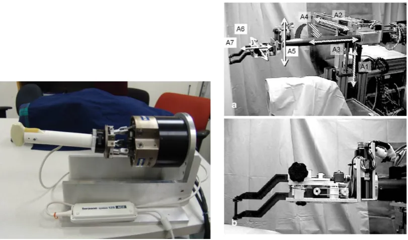
In 2005, (Kettenbach et al., 2005) developed a 7-DOF robotic arm, as observed in Figure 2.4
Right, which was registered to an hand-held ultrasound probe, with its position recorded by an optical tracking system. Its positional data was transferred to a planning system, which calculated the appropriate position, angle and pitch the arm should take for its appropriate configuration allowing for the use of the pre-planned insertion path. By reporting a mean deviation of the needle tip from the center of the target to be just 1.1+-0.8 mm, they proved the feasibility of in-vitro biopsies.
ultra-sound probe, the robot’s end effector and a specified point of entry on their custom phantoms to register the needle position with respect to the pre-obtained 3D ultrasound image of the area of interest. Their cylindrical needle guide was hinged direcly at a fixed distance to a beam integral to the probe, forcing the needle to stay in the imaging plane of the probe - allowing for its constant imaging on the ultrasound image. Nevertheless, this implementation led to make compromises between the best obtainable ultrasound image and the most convenient insertion point for the biopsy.
[image:16.595.82.488.306.545.2](Schneider et al., 2004) developed a robotic system for transrectal prostate biopsy performed under transrectal ultrasound (TRUS). Two parametric guides are placed on a sheath surround-ing an ultrasound probe around the circumference, to allow for rigid attachment with the probe while minimizing its interference with the image itself. All calibration required between the motorized 3 DOF robotic needle insertion mechanism with the TRUS device can be avoided due to those two component being rigidly coupled. A flexible needle could be then inserted through one of the sheath, accurately guided to any target in the prostate.
Figure 2.4: Left:6 DOF parallel robot as develloped by (Ding et al., 2008).Right:7 DOF robotic arm for
fine positioning develloped by (Kettenbach et al., 2005).
2.2.2.2 Intra-operative
Many of the previous procedures could gain further popularity by introducing real-time imaging processes. By combining intra-operative imaging and precision control of robotic sys-tems, better targeting accuracy and operation could lead to further improvement of minimally invasive procedures.
Real-time ultrasound guidance of surgical tools can be accomplished through hand-held tech-niques, but some studies also worked on robot manipulation, and integration, of both used surgical tools and ultrasound probes.
com-CHAPTER 2. OVERVIEW 9
plications may arise. Nevertheless, even with non-robotized ultrasound technique, manual operation of the ultrasound probe can provide guidance to some robotic systems.
As was discussed about the Neurobot, pre-operative MRI data for proper path planning are not sufficient when real-time leakage of fluids, causing brain shift, occur. Real-time ultrasound images compared with MRI images - possible through a burr-hole in the skull - with addition of probe tracking movements, allowed to update anatomic information about the patient, and therefore perform an updated surgical task.
Furthermore, common transrectal ultrasound devices are often used in simultaneity with the da Vinci system for prostatectomies. (Sotelo et al., 2008) showed the feasibility, as well as re-producibility, that such procedures, involving real-time image data gathering and performant robotic systems, are indeed realizable.
Robotically integrated ultrasound systems seem to be the natural next step for robotics in minimally invasive surgeries. Their main advantage lies in the control of the ultrasound scan-ning during the surgical procedure by the surgeon, instead of having to manually perform such action through an additional personnel in the operating room. It is easy to imagine an improved workflow of the procedure, and perhaps even automated scanning of the area of interest when there is need of updated imaging due to specific circumstances the system would judge necessary. Registration with pre-operative images could then be greatly improved.
Many scientific groups have developed tools interfacing with the da Vinci system.
(Leven et al., 2005) developed, for example, a telerobotic surgical system with integrated robot-assisted laparoscopic ultrasound capability. Their system consists of a rigid laparsocopic ul-trasound probe integrated on the daVinci robot, endoscope and ulul-trasound calibration, as well as video ultrasound probe tracking. (Schneider et al., 2010) developed a prototype dexterous laparoscopic ultrasound instrument for use with the da Vinci system, including image display and navigation tools. Their evaluation by surgeons including needle phantom lesion detection and needle biopsy was concluded very advantageous and with definite improved performance over traditional laparscopic systems.
3 Mechanism Design
3.1 Problem analysis
Let us remember that the main aim of the project is to present the design and prototyping of a novel steering needle manipulator for minimally invasive guided breast biopsy with ultimate purpose to improve clinical workflow.
To start with, it is essential that the developed system comprises of an housing for an ultra-sound probe, as this will allow for acquirement of intra-operative imaging in future related works. As it is necessary to mimic radiologists’ procedures, implementation of sensing for applying proper force between the probe and the patient’s skin should be considered. Also, an actuated mechanism must allow for future possibility of needle steering control. Change of the needle’s angle of insertion with the patient’s skin is key to properly targeting lesions at differing locations within the breast tissue.
Compatibility between the designed mechanism and the KUKA LWR arm must be assured. Ideally, an easy and quick fit could facilitate the introduction of such end-effector for future stakeholders, while allowing for personnel to satisfy reliability and sterilizability requirements. Furthermore, as this mechanism is aimed to be used in the future in the medical field, some applicable standards and regulations should be followed. Fail scenarios will allow us to work towards a design that does not, at any point, threatens personnel or patients surrounding it. It should then be possible to handle the mechanism by hand, by applying certain force/torque, so that back-drivability of the mechanism or the arm it is coupled to is possible.
In what follows, applicable requirements are summarized.
3.1.1 Requirements
The importance placed on the delivery of each requirement is achieved through MoSCoW pri-oritization.
[Must]
A set of requirements that is of the highest importance. A lot of emphasis, time and effort will be spent on those for comprehensive achievement.
[Should]
A set of requirements that is of secondary importance. It is encouraged to work towards achieving these, but failing to do so would not be considered as an issue.
[Could]
A set of requirements of the lowest importance. It is not of importance to fulfill those requirements, but could be of help for present and future work.
CHAPTER 3. MECHANISM DESIGN 11
1. Ultrasound transducer housing[Must]
The system must be mainly comprised of an housing allowing for easy attachment and incorporation of an ultrasound probe. As ultrasound probes can differ in sizes and shape, a mold for holding such device could be easily attachable and inter-changeable in case of need.
2. Needle imaging[Must]
The ultrasound probe must allow proper configuration with respect to the needle steering mechanism, providing perception of the needle’s orientation on the ultra-sound image.
3. Needle steering[Must]
The actuated mechanism must allow for future possibility of needle steering con-trol. This, in turn, will need to ensure lesion targeting.
4. Compatibility[Must]
The design must be such that it can operate on different characterizations of breasts’ anatomical structures.
5. Design criteria[Must]
The manipulator needs to provide reasonable precision and accuracy, lower than 10 mm, for lesion targeting. It should be robust, with play and friction of minimal values.
6. Weight[Must]
The apparatus should weight less than 10 kg so it can be attachable and manipu-lated by the KUKA LWR arm.
7. Fail safe[Should]
Worst case scenarios should be considered and the mechanism designed such that distinct characteristics occur when failure emerges.
8. Force Feedback[Should]
The force exerted by the ultrasound probe on the patient’s skin should be measured and provided as a sensory information.
9. Ergonomy[Should]
The end effector should allow the user to manipulate the needle steering mechan-ism compliantly in case of need. It should be comfortable to handle.
10. Disposability[Should]
The mechanism should compromise of disposable parts for convenient use and provide use of sterilized components.
11. Needle insertion[Could]
The needle holding mechanism allows for demonstration of automated needle in-sertion
12. Interchangeability[Could]
3.2 Conceptual design
3.2.1 Design Guidelines
In order to fulfill the requirements and the purposes the mechanism was designed for, certain design choices had to be made.
In recent years, the number of patients requiring breast biopsy has increased, leading to an enhanced number of skilled professionals carrying out those procedures and diagnoses. Appropriate practice is achieved by following well defined approaches that have proved, with time, to have the highest rate of accuracy and successful results. Following, the first thing to be reviewed are the steps taken in order to achieve successful ultrasound-guided core-needle biopsy of the breast. Indeed, mimicking biopsy procedures as done by professionals is one of the main aims of the developed mechanism and will allow for a discussion about the many advantages and limitations of those widely used techniques.
Nowadays, most biopsy procedures are carried out for patients with imaging studies revealing findings of BI-RADS category 4 and category 5, interpreted as the likelihood of the examined tissue to be 30% and 95% malignant, respectively. Being the preferred method in the field, ultrasound guided core biopsies are well tolerated and mostly used over surgical biopsies.
As it was discussed in theOverviewsection, the many advantages of ultrasound guided core biopsy of breast lie in the real time imaging of the procedure, low plausibility of complications and discomfort of the patient, easy access and availability of the used equipment, as well as cost and time conveniences. Nevertheless, several limitations such as difficulty to visualize and target findings, with possible restrictions directly related to the patients as, for example, the incapacity to cooperate with the surgeon, led professionals to devise and comply with basic procedure steps - a routine.
Assuming the procedure is carried in an appropriate operating room with conventional tools and devices usually required for breast biopsy, such as the availability to proper transducer probes or automated biopsy devices equipped with long needles, guided biopsy approach as the ’freehand’ technique is most commonly practiced. This method is described in (Parker et al., 1993) and consists of manipulating the transducer with one hand and the automated biopsy needle device with the other. The steps taken, as described in (Rocha et al., 2013), can be summarized in a chronological order as such:
1. Review of pre-operative imaging studies and perform an ultrasonography scan
2. Define the pathway to approach the lesion
3. Perform a triggering test of the automated biopsy needle device, couple it with a proper core biopsy needle - usual sizes varying from 14 Gauge (G), 16 G to 18 G
4. After properly positioning the patient, perform the antisepsis over the area around the lesion
5. Sonographically locate the lesion, inject the anesthetic agent through the pathway up to the lesion
CHAPTER 3. MECHANISM DESIGN 13
7. Insert the biopsy needle through the incision, reach the desired location and trigger the needle device
8. Slide the needle out of the patient’s breast, and retrieve the subtracted sample from the needle
9. Repeat from step 7 until a satisfactory number of samples is obtained
The developed mechanism’s duty lies in accurately positioning the needle to be inserted through the incision, so that the targeted lesion can be reached. As this is accomplished by varying the needle’s insertion angle around the incision point on the skin, we are looking into implementing a mechanism allowing for a Remote Center of Motion (RCM).
3.2.1.1 Remote center of motion
In favor of an intervention as minimally invasive as possible, there is need to be able to ma-nipulate surgical instruments about a fixed point on the patient’s body. This has lead to the development of manipulators that can output fixed rotational centers at certain distance from their structure (Kuo et al., 2012), with their workspace volume ensuring absence of collision with the the treated patient or the professional carrying out the procedure.
Mechanisms allowing for a remote center-of-motion (RCM), in which all links rotate about a fixed point, seem to correspond and fulfill the motions required for intervening as minimally invasive as possible in an efficient and effective manner.
As was discussed in theBackgroundsection, mechanisms allowing for RCM motions can be achieved in two different ways.
A remote center can be constrained virtually. A general multi-DOF mechanism with fine con-trol strategies and precise kinematic and dynamic model could achieve these goals. A pivoting motion can be obtained through coordinated control, as designed by (Dombre et al., 2004) for endoscopy procedures, where the instrument held by the mechanism is virtually pivoted at a trocar point. Those have some advantages over mechanical RCMs, such as increased maneuverability and easy changeable location of the pivot point.
Nevertheless, a specially configured robot accomplishing such motions based on its structural constraints itself seem to be a better alternative in terms of avoiding potential possible hazards due to possible control, sensing or modeling issues. Such RCM mechanism is mechanically locked based on its kinematics and has reduced DOFs, decoupled motion and additional con-troller simplicity.
In the design, it was desired to keep the simplicity and benefits of a mechanically locked RCM mechanism, especially due to enhanced safety, as well as its previous and tested use in the medical field. Nevertheless, as there are difference in morphology of treated patients such as variation of breasts size, a changeable location of the RCM point should be realizable.
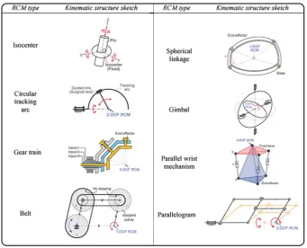
One way MIS robots are classified is based on their kinematic structures. In general, there are eight type of RCM mechanisms used: isocenters, parallelograms, synchronous belt trans-mission, spherical linkages, gimbals, circular tracking arcs, gear trains and parallel wrist mechanisms. (Kuo et al., 2012) illustrates well the eight RCM mechanism types, as can be seen in Figure 3.1.
Figure 3.1:RCM mechanism classification by kinematic structure (Kuo et al., 2012)
In order to be able to choose the best type of RCM apparatus suiting the project’s needs, kinematic design considerations were reviewed. This includes motion constraints - as extra-corporeal workspace volume, combined with the manipulation mobility, are of high import-ance. There is a maximum spatial volume the mechanism should take, and this is due to lim-ited area the whole system operates in. Let us bear in mind that the organ that is dealt with, the breast, is of significant size with respect to tools allowing for ultrasound guided breast biopsy, such as the dimensions of the probe itself. Also, with the purpose of being installed on a KUKA arm, collision possibilities of the hardware with itself should be considered. General issues might arise, such as human safety, so that a collision free workspace should be possible where unexpected position error from inaccuracies do not lead to irredeemable hazards to the sur-geon and the patient.
Isocentersseems to be most intuitive when talking about pivoted motions, with a circular ring
constraining the motion of an object within itself. Nevertheless, this kinematic structure offers three DOFs, three rotation pivoted at the RCM point, with an excessive degree of freedom going out of the 2D ultrasound plane and hence unfitting for the project’s aim.
Circular tracking arcsis composed of a circular track with a guided link sliding on it. This
CHAPTER 3. MECHANISM DESIGN 15
Gear trainsseems to require for tedious and complex design for the possibility of having a
mechanism with multiple DOF.
Belt transmissions simulates the function of parallelograms. Indeed, in theory, all
paral-lelograms of a parallelogram based RCM mechanism can be replaced by belt transmission. However, it seems that the change of location of an RCM for such kinematic structure would be rather complex to achieve with potential for backlash due to improper maintenance.
Spherical linkagesenforces all its moving bodies to rotate around a single point fixed in space.
Combined with circular tracing arcs, it could derive into an interesting RCM mechanism. Its part production tolerance, however, will strongly dictate the precision and accuracy of the RCM placement.
The structure of aGimbal based manipulator requires concentric extra-corporeal workspace around the RCM. Parallel mechanisms do not define the RCM point by the kinematics of the mechanisms. The RCM point is achieved with adequate control of the actuators on the manipulator. For MIS, we prefer mechanical RCMs, as was discussed beforehand.
Based upon previously discussed points, thorough literature review and considering the requirements to fulfill, aparallelogram-basedmanipulator allowing for a kinematically con-strained RCM is developed.
3.2.1.2 Modified parallelogram-based mechanism
A parallelogram-based mechanism is based on the combination of two parallelograms, with the RCM located at the point where two adjacent sides of those parallelogram are intersecting. An additional rotating motion can be obtained by pivoting the base by a revolute joint whose axis passes through the RCM point (Kuo and Dai, 2009b).
It is of no wonder that this kinematic structure is used in many developed MIS robots as it offers many advantages.
One main attractive feature of such mechanism is that the center of rotation is located at a tunable distance from the mechanism’s body. Many ways exist for the possibility to adjust the position of the RCM point such as playing with the links’ lengths, bending them, changing the manipulator’s base location..etc. Using a parallelogram structure provides higher stiffness over a serial mechanism, an upmost features to be assured as this, in turn, improves the mechan-ism’s targeting accuracy.
Next, this mechanism offers a relatively large movement range and high manipulability while still keeping a simple structure, allowing for simple analytical solutions for its kinematics.
Having a large number of linkages can be a main drawback of such kinematic structure. It could lead to interventions between linkages and lack of absolute rigidity due to the high number of revolute joints.
Figure 3.2:Singular configuration of a parallelogram, acquiring locally a second DOF
From the requirements and operations that need to be reproduced, a modified double paral-lelogram mechanism allowing for three degrees of freedom could be imagined. Its maneuver-ability can be such that one DOF allows for a micro operation, for rotation around the center of motion, and two of its DOF allow for a macro operation, placing this center of motion on a 2D plane external to the mechanism.
Themicrooperation consists of rotating the mechanism around a single point, the RCM,
ex-ternal to the the mechanism itself. This is achieved through the change of values of angle∆θ, as can be noted from Figure 3.5. A parallelogram based RCM mechanism can take several basic configurations, as given from (Zong et al., 2007) and observed from Figure 3.3.
Figure 3.3:Different configurations of a double-parallelogram mechanism (Zong et al., 2007)
It is clear that there is redundant constraints in theEDCBloop and that by eliminatingE,D,C orDconstraints several other configurations for the mechanism can be achieved.
[image:24.595.184.392.383.649.2]CHAPTER 3. MECHANISM DESIGN 17
Figure 3.4:Two possible solutions for
the installation of the needle sleeve’s attachment for RCM point mainten-ance
The installation of the needle sleeve should also be con-sidered. Such attachment will be at a certain distance from linkGH, yet the needle itself must rotate around the RCM.
Considering the RCM defined by the intersection of the line formed by linkAFand the inserted needle, there are two methods we could apply. The needle sleeve can be inclined by a certain angle to compensate for the the dis-tance between the sixth link,GH, and the needle sleeve -Figure 3.4 (a). A second possibility would be to bend AC rod to move the RCM a certain distance in order to meet the installation needs - Figure 3.4 (b).
The latter case was chosen for future ease of change of the needle sleeve without too much hassle, implementation purposes and due to the RCM workspace provided by the bent links features. The linkage is a Watt I type mechanism formed of four straight brackets, one bent bracket and one leaf. The leaf is composed of the sixth link stiffly coupled to the needle sleeve.
[image:25.595.163.450.395.566.2]The mechanism allows for the first bracket and the needle sleeve to rotate with respect to one another about a fixed center of rotation in the plane. The change of the location of the inter-section of two of the manipulator’s adjacent sides will modify the location of the point at which all linkages rotate about.
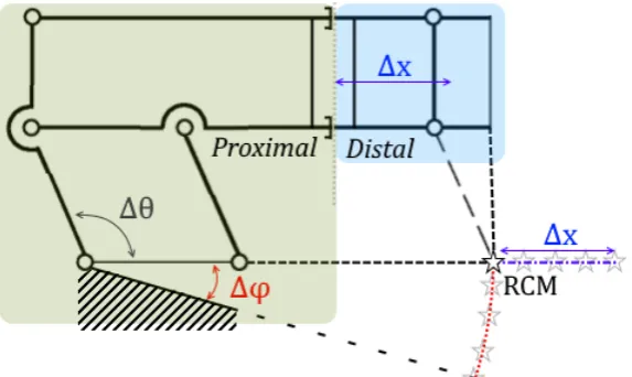
Figure 3.5:Principle of RCM positioning with variation of angle∆φand length∆x
Themacrooperation comprises of the change of values of angle∆φand length∆x allowing
the RCM point to travel on a 2D plane defined by those two variables - Figure 3.5. Although the reasons of defining one degree of freedom through the change of∆φ, the angle formed by the base of the double parallelogram to the remaining fixed mechanism, is mainly due for appropriate reach of the required RCM workspace, the change of∆xthrough the synced extension/retraction of both longest linkages allows for several additional advantages.
The proximal part of the mechanism allows for the change of∆φthrough the elevation of the double-parallelogram’s base, as well as for the change of the needle’s angle of insertion with respect to the skin.
The distal part of the system allows for change of∆xand is comprised of the needle sleeve, allowing for the required needle insertion motion and restricting the necessary degrees of freedom to achieve that. In order to vary∆x, two of the mechanism’s links can be adjusted in length, moving the distal part with respect to the proximal part. In this manner, the work point of the manipulator and the working radius of the apparatus can be changed. The use of telescoping links, for example, to achieve the needed motion, will allow the mechanism to require less ’backing up’ space away from the operating table. But also, the distal parts can be readily removed for sterilization if necessary, while the proximal part can be covered with sterile drapes.
An additional apparent advantage of such composition of the mechanism is that most drivers can be stationary placed on the base of the manipulator, minimizing the mass of moving link-ages. All the actuators can be mounted on the proximal part of the apparatus and electrically isolated from the manipulator in order to reduce shock hazard to the patient. It may be further imagined that no distal component requires electrical power or even the presence of conduct-ive or metal parts, thus simplifying sterilization, compatibility with medical imaging devices such as Computed Tomography (CT) and Magnetic Resonance Imaging (MRI), electrical safety, and further reducing the bulk of the distal portions of the system.
Having discussed about the needle manipulator, it is important to provide proper imaging modalities granting the capacity to target malignant lesions. Ultrasound images are possible to acquire by suitably operating an ultrasound probe for scanning the area of interest.
3.2.1.3 Ultrasound probe housing
Ultrasound scannings (US) allows to examine the internal structure of soft tissue safely and non-invasively. Nevertheless, an important feature of such imaging modality is the require-ment of physical contact between the probe and the patient.
Figure 3.6: Force measurement
apparatus, measuring contact force
Fcont ac t between the patient’s skin
and the scanning probe When used in the ’hand-held’ technique, the radiologist,
operating the ultrasound transducer, is responsible of holding the probe in contact with the skin and adjusting its orientation and position to obtain a scan plane of the tissue of interest. By applying forces on the probe, the tissue deforms by a certain amount with regard to its composition. Contact forces are intentionally varied by the professional in order to induce an improved image quality. Nevertheless, this makes ultrasound images hard to reproduce. For a repeated scanning procedure on the same tissue of interest, deformations will defer due to the change of applied contact forces and mechanical proper-ties of tissue structures.
Repeatability issues result in complicated fusion between
CHAPTER 3. MECHANISM DESIGN 19
In order to reproduce ultrasound scans independent on the pressure applied by the probe on the skin, measurements of the involved forces, for prediction and correctness of the induced deformations, should be acquired. Evidently, the differing mechanical properties of tissues from one patient to another requires this prediction to be patient-specific, and be well com-prehended.
In consequence for such data gathering, the housing will need to incorporate some kind of force sensing. The force that the ultrasound probe applies to the tissue during scanning is equivalent to the force the tissue applies to the probe itself - as from Newton’s third law of motion those two are of opposite direction, but of equal magnitude.
Using a six DOF force transducer let us measure three torques and three forces. Such device can be rigidly attached to the ultrasound probe on one side, and an enclosure on the other. By allowing the probe to extend from the bottom of this enclosure, the probe can make direct contact with the skin - Figure 3.6. As a result of enclosing such set-up, any contact between the probe and other external sources can be avoided.
Given the probe is moving at slow pace during the data and image acquisition, its acceleration can be omitted. WithW its weight, and by force equilibrium,Fcont ac t is described by
[image:27.595.120.208.393.454.2]Fcont ac t= −Fmeasur ed−W (3.1)
Figure 3.7: Modeled mold of the
Siemens ultrasound probe 14L5, for rigid attachment of the probe to the force sensor
A 3D scan of the ultrasound probe used in breast biopsy in hospitals across the field yields to a 3D model. With the use of the ultrasound probe 14L5, a 14-5 MHz linear transducer for breast imaging from Siemens, we were able to create an appropriate mold, as per Figure 3.7, for ri-gid attachment between the probe and the force sensor that is implemented in the system. This simple activity, of 3D scanning and mold creation, can allow for the printing of appropriate molds for different ultrasound transducer probes easily and efficiently. From Figure 3.7 the rendered mold of the Siemens 14L5 for rigidly clamping the ultra-sound transducer can be observed. The three centered holes allow for fixing the mold to the force sensor with screws, while the four external holes allow for rigidly at-taching both shells.
3.2.1.4 Fail safety
An important requirement for the mechanism is being able to deal with bad case scenarios. Indeed, the system should be designed in such way that when failure emerges a distinct char-acteristic can occur, and consequences do not lead to any damage done to parties involved in the operation. Even though the prototype developed in this paper is only the first stage for obtaining a commercial and robust product for the MURAB project, we are still concerned with elements making the system fundamentally safer.
A system allowing for ultrasound probe positioning should be safe in any circumstance. It should be light enough and of limited force ability, allowing for scanning the desired area of interest in a safe manner.
Fail scenarios can emerge for several reasons, one of them being control issues. Issues concern-ing control or coordination failure can create potential safety hazards for all parties involved in the workflow in which the system operates. When the telescopic links, for example, are not properly synced, it could result in a improper placement of the RCM. In another case, the controller electronic design that monitors the power supply could turn out to be faulty. But numerous different problems can emerge, such as collisions, pinching, clamping due to non-proper path planning, shock hazards and more.
Fortunately, certain design choices can allow to circumvent such scenarios in case of need:
• Having a kinematically constrained RCM mechanism. This choice being the first stride to provide safety to the environment in which the mechanism operates. The possible lim-ited configurations of such system can be easily predicted and provides the possibility to define strict workflow for operating the apparatus. This also avoids motion singularities and allows for simple stable control.
• Dividing the system into proximal and distal sections for reducing the chances of shock hazards and improved possibility for sterilization, see Section 3.2.1.2.
• An easy needle holder detachment. This allows for any wrong going scenarios to be treated as during usual hand-held operations. Decoupling the needle in an easy and quick manner allows the surgeon or operator to worry thoroughly about the patient herself, without the need to be concerned about the manipulator.
• Slowing down the operating motion of the mechanism. Even though slowing down the actuators can cause overall functioning of the robot to be tedious, velocity limits on the servo output can be an easy implementation for assisting in the overall safety of manipulating it.
• An ergonomy allowing for easy movement by external applied torque/force, as well as minimizing chance of damage in case of collision. e.g. rounding edges.
In future work and prototype iterations, the controller electronics can be designed such that the power supply and cable integrity are monitored. In addition to provide redundant position encoders on each actuated joint, kinematic safety and unwanted motion in case of power failure can be ensured by implementing emergency brakes on the primary degrees of freedom. Finally, gravity balancing should be considered, offering redundancy to emergency brakes in case of undesirable motion.
CHAPTER 3. MECHANISM DESIGN 21
need of backdrivable or non-backdrivable actuation; e.g. the actions to be taken if the robot becomes rigid and the surgeon needs to withdraw the tools used on the patient will greatly depend on the possibility to remove or not the instrument carrier from the manipulator itself -such as take apart the distal part away from the mechanism. Further review about backdrivab-ility in surgical manipulators can be found in other papers, such as (Funda et al., 1995).
3.3 Detailed design
In this section, a thorough study of the design of the mechanism is carried out. First, the for-ward and inverse kinematics are computed, allowing for workspace analysis of the manipu-lator. An analysis of loads acting on the system, in static equilibrium with the environment, is then performed. Finally, a design concept aiming towards the previously carried conceptual design is presented.
3.3.1 Kinematics
3.3.1.1 Forward Kinematics
[image:30.595.84.488.256.497.2]The forward kinematics problem is to determine the position of the end-tip point of the mech-anism when given values of the joint parameters.
Figure 3.8: Modified double parallelogram mechanism with variables, parameters and frame
assign-ments
Assume the origin of the coordinate system on the ultrasound probe,O, at the source of the ultrasonic waves of the transducer.
CHAPTER 3. MECHANISM DESIGN 23
Parameter / Variable Description
µ angle compensation of the needle’s offset γ angle between y-axis and housing surface
θ angle between needle steering mechanism base and linkL3a φ angle between y-axis and needle steering mechanism base
α angle formed at the first joint of the mechanismJ0, between the x-axis
and jointJ1
χ angle between the housing surface and the line segment passing through joints J0andJ8,J0J8
² angle between the line segment passing through jointsJ0andJ8,J0J8, and linkL1
ρ angle between the line segment passing through jointsJ0andJ1,J0J1, and linkL1
Lo needle’s offset with respect to linkL6
lm length of the line formed by the first joint of the mechanism,J0, to jointJ1
L5 length of the fifth link;L5a+L5b
Li needle’s insertion depth; defined from the intersection of the lines collinear to linkL4b andL7, respectively
L2 length of the second link
x0&y0 coordinates of jointJ0
xr&yr coordinates of the RCM point
In order to derive the forward kinematics angleµis define as
µ=sin−1(Lo L2
) (3.2)
For a knownφ, the angle between the needle and the x-axis can then be written as
β=(φ+θ)−(π
2+µ) (3.3)
Furthermore,xLm=LmcosαandyLm=Lmsinα, with
α=π
2−(γ+χ+(π−(²+ρ)) (3.4)
WithL5=L5a+L5b, and as it can be observe from Figure 3.5, the distance between jointJ1to
the RCM point is equivalent to the distance between jointsJ5andJ6. Knowing the coordinates
of jointJ0and of jointJ1, the position of the remote center of motion can be found as
xr=x0+L5sinφ+xLm
yr=y0−L5cosφ−yLm
(3.5)
And finally, the position of the tip of the needle,
xe=xr−(Li−L3b) cosβ ye=yr−(Li−L3b) sinβ
(3.6)
Obtaining angleφ
Angleφis obtained throughout operating the linear actuator moving joint J9on lineDA.
As-sume a line passing through jointsJ0andJ8, this line crosses the line passing through jointsJ1
[image:32.595.219.383.181.470.2]andJ2, collinear to linkL1, forming a constant angle², as can be observed from Figure 3.9.
Figure 3.9:Close-up of the variation of angleφmechanism
Let us assume the initial position of the nut to be defined by pointD. In order to obtainχwith respect to the advancementMof the nut on the leadscrew, also defined as the distance between pointDand pointA, the following steps are carried:
• Obtainγ, the angle between the y-axis and housing surface. Since the lead screw is paral-lel to the housing surface, this angle is similar to the one between the y-axis and the line passing through the lead screw.
• Obtain the coordinates of jointJ9, which will be denoted as pointA. ∆x=xA−xD
∆x=Msin(γ) xA=Msin(γ)+xD
(3.7)
∆y=yA−yD
∆y= −Mcos(γ) yA= −Mcos(γ)+yD
CHAPTER 3. MECHANISM DESIGN 25
• Define the equation of the line passing through pointsA andD. A common form of a linear equation in the two variablesxandyis
y=bx+c (3.9)
Withb=∆∆yx. By replacing the coordinates of a point known to be on the line, such asxD andyDfor example,ccan be computed.
• Withaandbconstant lengths, pointBcan be defined as an intersection of two circles
||B−A|| =a V
||B−C|| =b. As pointCis static, it can be solved forxBandyBthe following equations, giving two plausible solutions:
(xB−xA)2+(yB−yA)2=a2 (xB−xC)2+(yB−yC)2=b2
(3.10)
Since singular position of the mechanism is never reachable, so that pointsD,AandB are not once collinear, the solution wherexA<xB is picked.
• PointBcan be translated in order to obtain a new point,R, so thatBCARforms a paral-lelogram. PointRis then defined as
xR=xA+(xB−xC)
yR=yA+(yB−yC) (3.11)
• LetQbe a point on lineDA, withxA<xQ. From the cosine rule,
QR2=AQ2+AR2−2·AQ·ARcosχ χ=arccos(AQ
2
+AR2−QR2
2·AQ·AR )
(3.12)
WhereQR,AQandARare the lengths defined by pointsQ&R,A&QandA&Rrespectively, such that
AQ=
q
(Ax−Q x)2+(Ay−Q y)2
AR=
q
(Ax−R x)2+(Ay−R y)2
QR=
q
(Q x−R x)2+(Q y−R y)2
(3.13)
• Furthermore, assuming
∆xBC=xB−xC
∆yBC=yB−yC
(3.14)
in the case¯¯ ¯
∆yBC ∆xBC
¯ ¯ ¯> ¯ ¯ ¯ ∆y ∆x ¯ ¯
¯, it is important to note thatχwill be of negative value.
Angleφcan then finally be computed as
φ=γ+χ+(π−(²+ρ))+ρ−π
3.3.1.2 Inverse Kinematics
Inverse kinematics allow the use of the kinematics equations to determine joint parameters providing a desired position of the end effector. It is useful in transforming motion plan into joint actuator trajectories, used in future works to control the mechanism.
Let us remember the previously defined parameters. For givenxr andyr, Equations 3.16 can be solved in order to obtain the values ofφandL5.
xr=xC+(L5+lo)·sinφ+xlm
yr=yC−(L5+lo)·cosφ−ylm
(3.16)
So that for a given RCM point,τcan be computed as
τ=(π+φ)−γ−ρ−(π−(²+ρ))
τ=φ−γ+² (3.17)
From Equation 3.3 it can also be written
θ=β−φ+(π
2+µ) (3.18)
Following similar steps that were performed in theForward Kinematicssection, the coordin-ates of pointA,xAandyA, can be written with respect to the advancementM:
∆x=xA−xD
∆x=Msin(γ) xA=Msin(γ)+xD
(3.19)
∆y=yA−yD
∆y= −Mcos(γ) yA= −Mcos(γ)+yD
(3.20)
Furthermore, the coordinates of pointQ,xQandyQ, can be written with respect toxAandyA. Forcstany positive constant value,
xQ=xA+cst yQ=∆y
∆x+
(xD−∆y ∆x·
yD)
Also, solving forxB andyB, the coordinates of pointBwith respect to the coordinates of point Acan be obtained from Equation 3.21. For further parametric evaluation, see Appendix A.
a2=(xB−xA)2+(yB−yA)2
CHAPTER 3. MECHANISM DESIGN 27
Finally, the coordinates of pointR,xRandyR, are computed as
xR=xA+(xB−xC)
yR=yA+(yB−yC) (3.22)
Given a certainχand all points defined with respect toxAandyA, which is itself defined with respect to the value ofM, it can be written
QR2=AQ2+AR2−2·AQ·ARcos(χ) χ=arccos(AQ
2
+AR2−QR2
2·AQ·AR )
(3.23)
whereQR,AQandARare the lengths defined by pointsQ&R,A&QandA&Rrespectively.
3.3.2 Workspace Analysis
Many robotic systems developed for medical purposes lack systematic methods to compare their design or evaluate their kinematic configuration in application tasks (Cavusoglu et al., 2001).
During design stage, it was important to differ between different design alternatives and eval-uate kinematic abilities of such designs in order to perform the required duties - while always assuring for such operations in the volume area defined by the patient’s anatomy.
By running tool motions during those tasks throughout the inverse kinematics of the manip-ulators, it was possible to verify that the system can satisfy the desired motions. This allows us to study the performance of given motions and plausible configurations by assuring the end-effector’s trajectory lies permanently within the workspace of the manipulator.
3.3.2.1 Angle and location of the needle’s insertion point
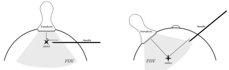
[image:35.595.107.478.567.680.2]A critical point in the procedure for attaining proper mechanism’s workspace is in the needle’s entry/insertion point on the patient’s skin, and the needle’s angle of insertion in the breast.
Figure 3.10: Left: Needle insertion with respect to the ultrasound probe for shallow lesion targeting.
Right:Needle insertion with respect to the ultrasound probe for deep lesion targeting.
Hence, the recommended insertion area is in the peripheral curvature of the breast, position-ing the needle at approximately 4-6 cm away from the edge of the transducer. Furthermore, the needle is preferably inserted while perpendicular to the transducer and parallel to the chest wall for imaging and visualization conveniences, Figure 3.10, as well as reduction of the risk for pneumothorax. It is important to note that even for deeply located lesions, when oblique needle access is necessary, the preferred position of the transducer tends to always be perpen-dicular to the needle - right portion of Figure 3.10. For very deep lesions, it is possible to move the lesion away from the chest wall by moving the needle towards the skin surface while the needle is already inserted in the breast - Figure 3.11.
[image:36.595.223.351.217.329.2]Figure 3.11
Figure 3.12:Alternative of needle reach for deep lesion targeting
3.3.2.2 Distribution of the breast’s dimensions
When modeling the interaction between the breast and some imaging system, it is important to understand the characteristics of the breast’s anatomy. This also allows for proper modeling of breast phantoms for testing purposes, both computer generated and physically originated. It seems necessary to study the breast’s size distribution of the general population, even though it should be kept in mind that differences in the anatomy of breasts from one individual to another are existent.
Several papers cover the characterization of breast anatomical metrics, such as in (Huang et al., 2011). In order to reach the workspace of interest for performing successful procedures, two characteristics are of main importance: the breast deepness and diameter near the chest wall for different cup sizes.
Figure 3.13: Histogram of the distributions of the breast diameterDchest w al l near the chest wall for
CHAPTER 3. MECHANISM DESIGN 29
Generally speaking, the breast shape is characterized by the breast’s effective diameter, gradu-ally decreasing from posterior to anterior. It can be observed that the mean breast diameter, Dchest w al l, increases with the bra cup size. The mean breast diameters (±standard error) for bra cup sizes A, B, C and D are 11.1±0.5, 11.4±0.2, 13.0±0.2 and 13.7±0.2, respectively.
As the cup size is defined by the difference of measurement of an individual around the rib cage, under bust measurement and full bust measurement, it is safe to assume that for a D cup size the difference between the thoracic cage and the tip of the needle does not exceed 8 cm.
3.3.2.3 Ultrasound workspace
The ultrasound workspace considered is primarily defined by its depth and Field Of View (FOV), which is the area scanned by the ultrasound transducer and creating a 2D image.
It is important to note that for most breast biopsies, radiologist use convex or curved array ultrasound transducer types where the maximum angular extent is the FOV. This is due to the fact that in the last ten years breast imaging has gone to very high frequencies (e.g. 14 MHz) (Szabo and Lewin, 2013). Most ultrasound probes used today, in practice, offer a FOV of approximately 60◦to 70◦.
The depth control alters the vertical FOV of the image, inversely proportional to the frame rate - so that increasing the depth increases the time taken for the signal to return back to the trans-ducer, decreasing the frame rate.
As in practice the thoracic cage is almost always observable at the bottom of the ultrasound im-age when scanning the breast area, it can be assumed that the depth of the ultrasound imaging corresponds to the depth of the patient’s breast.
3.3.2.4 Mechanism workspace and size synthesis
The mechanism’s workspace should cover the area of interest for placing the RCM on the sur-face of the patient’s skin. Considering the previously noted points, the following features need to be taken into account when defining the workspace of the RCM point of the mechanism:
• The needle’s entry point should be at approximately 4 to 6 cm away from the transducer probe’s edge, depending on the breast’s size.
• The needle should ideally always remain perpendicular to the transducer, parallel to the chest wall.
• Breast sizes vary, with the diameter of the chestwall within the range of 12 to 17 cm.
• The maximum depth the needle should reach corresponds to the maximum depth reach-able for big breasted patients, which does not exceed 8 cm.
• The ultrasound image is defined by the characteristics of the ultrasound probe. For a curved array ultrasound transducer type, it is assumed that the FOV is of 70◦and reaching as deep as the thoracic cage of the patient.
Using the previously calculated kinematics of the mechanism, it is possible to plot the pos-sible locations the RCM could take with respect to different breasts’ dimensions, and for certain given parameters of the mechanism - Figure 3.14.
Figure 3.14:Lateral view of possible RCM locations with respect to two different breast sizes
Obtaining a workspace as is seen in Figure 3.14, and with given initial anglesθ0=π2 andφ0=0,
can be achieved by defining the mechanism’s parameters as such:
Linkage(s) Length [mm]
Lo,L7 20
L1,L2,L3a,L3b,L6 50
L4,L5 100to140
L8 44.3
Angle Degree [◦] φ -13.17to14 θ -55to115
[image:38.595.117.451.552.752.2]In addition to the possibility to place the RCM point at the desired locations, it is important to examine the needle’s reach inside the breast. As lesions could be superficially located, or could be present at the deepest point of the breast, it is important that our mechanism covers the whole workspace of the ultrasound image. For different extremeties of angleθ- hence for its maximal and minimal values - Figure 3.15 can be plotted for four different RCM placements. It is clearly observed that coverage of shallow lesions, located near the patient’s nipple, allow for the needle’s reach given any insertion point. Nevertheless, for reaching deep lesions, the RCM entry point should be located at a minimal distance from the mechanism’s housing.