1
Faculty of Electrical Engineering,
Mathematics & Computer Science
Traffic Filtering Based
on Subsystem Component State
Alpha O. Diallo M.Sc. Thesis
August 2017
Supervisors:
Abstract
Firewalls while able to filter traffic for which they have rules for are susceptible to allowing traffic that could have negative impacts on the state of an industrial control system (ICS). In order to be able to block traffic that looks legitimate but may cause the ICS system to go into unwanted states the firewall needs to consider the current state of the system and how the traffic may change this state. In this thesis the 1996 IEEE 24 bus one area reliability test system and the IEC 60870-5-104 proto-col are used to represent an ICS power system and the traffic format respectively. Two methods, minimum and maximum bus connections, and branch power correla-tions, are used to define critical components that provide information about the ICS system. These critical components are modeled within the firewall and checked for violations whenever traffic that can change the system, identified through inspection of fields in the IEC 60870-5-104 protocol, is processed. The false positive and nega-tive rates, and accuracy of the firewall are evaluated for different cases where critical components are identified by one of the two methods. Results from this thesis show that using branch power correlations to identify critical components and incorporat-ing that information into the model helps to filter out traffic but can be improved with the addition of correlations between bus voltages.
Acknowledgements
First off, I would like to thank Justyna Chromik for all the encouragement. Justyna has been there from the start when I was still trying to come up with a research topic. Throughout the email exchanges, skype calls, and in person conversations she has provided helpful feedback and direction in my research and writings, and always asked questions to make me consider why I’m doing something.
In addition, I would like to thank Boudewijn Haverkort and Anne Remke for being part of my supervisory and graduation committee and providing helpful feedback during my intermediary presentations. I would also like to thank Fabio Massacci from the University of Trento for providing help in revising.
Lastly, I would like to thank Ries van Son and Compumatica Secure Networks for allowing me to work on this thesis and my minor thesis at Compumatica.
Contents
Abstract iii
Acknowledgements v
1 Introduction 1
2 Background 5
2.1 Introduction to ICS Security . . . 5
2.1.1 Architecture Security . . . 7
2.1.2 Protocol Security . . . 8
2.2 Industrial Firewalls . . . 9
2.3 Previous Work on Firewalls . . . 10
2.3.1 Whitelisting . . . 11
2.3.2 Dynamic Packet Inspection . . . 12
2.3.3 System State Consideration . . . 12
2.4 Discussion . . . 13
3 Methodology 15 3.1 1996 IEEE 24 bus Reliability Test System . . . 15
3.2 IEC 60870-5-104 Protocol . . . 15
3.3 Critical components of an ICS system . . . 20
3.4 Modeling the Critical Components in the Firewall . . . 21
3.5 Identifying Changes in ICS System Due to Traffic . . . 27
3.6 Test Setup . . . 27
3.7 Discussion . . . 30
4 Results 33 4.1 Correlation Results From Command Sequence A . . . 33
4.2 Firewall Results For Command Sequence A . . . 35
4.3 Firewall Results For Command Sequence B . . . 36
VIII CONTENTS
5 Conclusion 39
5.1 Limitations . . . 41 5.2 Future Work . . . 41
List of Figures
1.1 Vinyl Acetate Monomer Process . . . 2
2.1 ICS vulnerability, exploit, and malware count per year [24] . . . 6
2.2 ISA-99 Purdue Model [33] . . . 7
3.1 1996 IEEE 24 bus RTS . . . 16
3.2 IEC 104 APCI I-Format with ASDU . . . 17
3.3 APCI S-Format . . . 18
3.4 APCI U-Format . . . 18
3.5 LoadItem classes with variables and methods . . . 22
3.6 BranchItem classes with variables and methods . . . 22
3.7 GeneratorItem classes with variables and methods . . . 23
3.8 BusItem class with variables and methods . . . 24
3.9 Main model driver program . . . 25
3.10 ASDU with fields that are inspected to determine if packet information is sent to model . . . 28
3.11 Interactions between firewall, model, and ICS system . . . 30 4.1 Graphs showing branch correlations with linear regression equation . 34
List of Tables
2.1 Firewall advantages and disadvantages . . . 9
3.1 Bus connections . . . 20
3.2 Process commands with type identification and information object el-ements. . . 26
3.3 Command Sequence A. Commands with red background indicate vi-olations occurred. . . 28
4.1 Contingency table for command Sequence A packets indicating false positive and negative and true positive and negative conditions. . . 35
4.2 Firewall results for command Sequence A. . . 35
4.3 Command Sequence B . . . 37
4.4 Contingency table for command Sequence B. . . 37
4.5 Firewall results for command Sequence B . . . 38
Chapter 1
Introduction
Industrial Control Systems (ICS) encompass a multitude of different systems includ-ing Supervisory Control and Data Acquisition (SCADA) and Distributed Control Sys-tems (DCS). These sysSys-tems are used in water treatment plants, buildings, factories, and electric grid systems. They are a combination of sensors for monitoring and collecting data on the real world and actuators which perform physical actions in the real world. Along with the sensors and actuators, programmable logic controllers (PLC), remote terminal units (RTUs), and intelligent electronic devices (IEDs) are used for decision making processes. ICS systems used to be isolated systems with-out any connections to other networks, but now, with the use of commercial off the shelf technologies and internet of things devices, they are more exposed. In order to provide some form of protection to ICS systems, firewalls, which are one of the recommended security measures for Critical Infrastructures by the National Institute of Standards and Technology (NIST) [10], are used.
Firewalls are used to segment networks and filter out traffic. Some firewalls within ICS use whitelisting and deep packet inspection to filter packets, but these techniques are not enough. Packets that contain legitimate content can be used to cause an ICS system to go into an unwanted state by sending multiple packets that each contain legitimate commands to change the systems configurations (compo-nent values). In order to be able to filter out these kinds of packets, the state of the system needs to be tracked and the impact of these packets on the systems state must be known before deciding to allow the packet through.
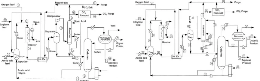
As an example consider the Vinyl Acetate Monomer process [11] in a chemical factory in Figure 1.1. The picture on the left shows the process without the location of the control valves, while the one on the right shows the control valves. The pro-cess produces vinyl acetate by converting ethylene, oxygen, and acetic acid through vapor reactions. In this process some of the gases are recycled through the system. The system has safety constraints, such as oxygen composition and pressure in the gas recycle loop being less than 8 mol % and 140 psia, respectively. There are
2 CHAPTER1. INTRODUCTION
[image:14.595.69.502.256.392.2]operational constraints such as the reactor and reactor inlet temperature being less than 200 Celsius and greater than 130 Celsius, respectively. The system could be attacked by sending multiple legitimate commands to open and close the control valves. By sending these commands the ratio of the chemicals can be changed, for instance making it so that the oxygen composition becomes 8 or more mol percent-age, thereby violating the safety constraint. The temperature in the reactor can be made to go greater than 200 Celsius by keeping the control valve on the steam outlet closed, or by changing the setpoint level of the temperature, leading to mechanical damage.
Figure 1.1: Vinyl Acetate Monomer Process
These legitimate commands can pass through firewalls that use only whitelisting or deep packet inspection leading to safety violations and mechanical damages. By taking the state of the system into consideration these commands can be stopped at the firewall, by analyzing the impact of the commands on the state of the system before letting the commands through.
3
in section 2.
This thesis looks at simplifying the model of the controlled physical system and using information about a subset of components which are deemed critical for the system to filter traffic. For instance, in the vinyl acetate monomer process example given, critical components could be the reactor (temperature sensor), pressure sen-sor in the gas recycle loop, and control valves for the steam and ethylene, acetic acid, and oxygen gases. With this concept, not all system variables need to be ob-served or modeled. The main research question that is addressed in this thesis is:
Whether knowing the state of critical components helps to better filter out traffic that could cause the system to go into an unwanted state?
To help answer this question several sub-questions are asked in order to learn about the system and about how traffic would be filtered. These sub-questions are:
1. What are the main critical components in the ICS system under study? 2. How would the critical components be modeled?
3. How do we know when the current traffic will make these components change the state of the ICS system?
By answering the identified questions, contributed knowledge includes whether providing knowledge on a subset of components within a system to a firewall can help it to better filter out traffic. Moreover, a proof of concept firewall is designed, that is based on the idea of using information about a subset of the system components to filter out traffic that would otherwise lead to an unwanted system state.
Chapter 2
Background
The main focus of this chapter is to provide background information on ICS systems and one of the security mechanisms, firewalls, used to protect these systems to the reader. Security issues within ICS systems are discussed in section 2.1 followed by a description of firewalls in 2.2. Section 2.3 includes information on the different types of methods that have been proposed on filtering traffic in firewalls.
2.1 Introduction to ICS Security
ICS systems were once isolated systems that did not have any connection to the internet. If someone wanted to hack into the system they would need physical ac-cess, but this has been changing. These systems now have internet protocol (IP) addresses which can allow for remote access to the system. The protocols that are used, such as MODBuS,DNP3, and IEC 60870-5-104, are encapsulated within transport control protocol (TCP) to allow for routing in the internet. The technology and integration with the web allows corporations to obtain realtime data from the ICS system to streamline their operations. Maintenance crews and workers mon-itoring these ICS facilities are able to take measurements of devices and perform calibrations without having to approach them [23].
With the exposure of ICS systems to untrusted networks, more and more vulner-abilities within these systems have been found over the years. Figure 2.1 shows the number of vulnerabilities, exploits, and malware targeting ICS systems for the years from 2001 to 2014. The spike in 2011 and after could be attributed to the discovery of Stuxnet, which was found to be targeting particular ICS systems that matched certain requirements. In this case it ended up being an Iranian nuclear facility where Stuxnet was able to make modifications to the system but provide false readings to observers that indicated the system was operating normally, even though it was not. After Stuxnet, attackers and more researchers alike took interest in ICS
6 CHAPTER 2. BACKGROUND
Figure 2.1:ICS vulnerability, exploit, and malware count per year [24]
tems leading to more vulnerabilities being discovered indicating that ICS systems were not very secure. A more recent example of malware targeting ICS systems is CrashOverride [25], which is the first known malware designed to attack electric grids. CrashOverride was used in a cyber attack on a transmission substation in Kiev, Ukraine in December 2016. From an analysis of the malware done in [25] different modules were found such as an IEC 60870-5-104 module, and IEC 61850 module. Both of these modules are related to electric utilities as IEC 104 and IEC 61850 are both protocols used in electric utilities. The analysis also revealed that module extensions were possible, so the malware could be used in industries other than the electric industry.
2.1. INTRODUCTION TO ICS SECURITY 7
measurement with false data that may have been gathered earlier in time. The in-tegrity of the data must hold otherwise it could cause the ICS system to go into an invalid or dangerous state. Confidentiality is the prevention of access to or use of an asset by an unauthorized entity. A violation of the confidentiality attribute within ICS systems could be an attacker gaining unauthorized access to configuration files.
These security attributes can be violated by malware that gets into the process network through another network such as the corporate network or through the use of an infected device. The protocols used by ICS systems can also be used to help in violating these security attributes. ICS systems can be vulnerable to exploit due to the architecture of the ICS system and ability to misuse the industrial protocols being used. Some of the possible ICS architectures used and the possible threats they pose will be explored next, followed by possible misuse of protocols.
2.1.1 Architecture Security
ICS systems can be connected to corporate networks as well as vendor networks. These connections can cause the ICS system to be vulnerable unless the networks are properly segregated. An architecture that provides the weakest form of
[image:19.595.93.536.414.737.2]8 CHAPTER 2. BACKGROUND
tection for an ICS system is one that uses dual network interface cards to allow for communication between two networks. In this architecture both networks have a direct connection to each other, so if there is an intruder or malware on one of the networks then they could move into the other network, without much effort. In order to provide greater security, the recommendations for ICS systems are to seg-regate the ICS network from all other networks and to provide a de-militarized zone [30,31,32] where untrusted networks can get data from if they need it, without having to have a direct connection to the ICS system.
The ISA-99 Purdue model in Figure 2.2, shows the type of recommended archi-tecture for ICS systems. The model provides segregation at different levels starting from the local control at level 1 all the way up to the Enterprise network at level 4. This type of architecture provides defense in depth with multiple countermeasures in the form of firewalls. If an attacker wanted to get to the local operator stations at level 2, and did not have a way to physically access any of the devices at that level, then they would need to first compromise several systems and find ways to bypass the firewalls.
2.1.2 Protocol Security
2.2. INDUSTRIALFIREWALLS 9
commands they are trying to run.
2.2 Industrial Firewalls
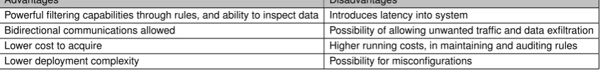
[image:21.595.94.531.389.440.2]Firewalls provide network segmentation along with the enforcement of rules set by administrators, and has both advantages and disadvantages, such as those listed in Table 2.1. Modern firewalls are able to analyze and filter out data on all layers of the OSI model. With ICS systems, firewalls can be used to provide segmentation between the corporate network and the ICS system, as well as inspect the traffic that is traveling between the two networks. Traffic is filtered through the use of rules, and sometimes there are many rules that a firewall checks traffic against, which can introduce latency into the network. ICS systems have real time requirements and so this latency can prevent them from completing a task within a predefined time limit, which can cause problems.
Table 2.1: Firewall advantages and disadvantages
Advantages Disadvantages
Powerful filtering capabilities through rules, and ability to inspect data Introduces latency into system
Bidirectional communications allowed Possibility of allowing unwanted traffic and data exfiltration Lower cost to acquire Higher running costs, in maintaining and auditing rules Lower deployment complexity Possibility for misconfigurations
Firewalls being able to inspect and analyze the content, at the application layer, of the traffic coming to them is very beneficial in ICS systems. ICS traffic has to be inspected in order to be able to understand what the traffic content is doing to the system, and without this inspection, the traffic would look all the same. An example of this would be with the MODBUS protocol, where the MODBUS read and MODBUS write commands would look the same without inspection. With deep packet inspection if a MODBUS write command is sent that is going to perform an unauthorized write operation, then this can be caught and the traffic can be filtered out.
The effectiveness of a firewall can be judged by its accuracy in correctly classi-fying the traffic that comes to it. The accuracy can be measured by collecting data on the number of false positive and false negatives, along with the true positive and true negatives. The definitions for true positive and negative and false positive and negative are given as follows:
True positive: Correctly classifying malicious traffic as malicious. True negative: Correctly classifying safe traffic as safe.
10 CHAPTER 2. BACKGROUND
False negative: Incorrectly classifying malicious traffic as safe.
Having too many false positives means that the firewall is restricting legitimate traffic, which could be crucial to the functioning of the ICS system, from passing through. Having too many false negatives creates a false sense of security since malicious traffic is being let through without being blocked. This malicious traffic could be to change the setpoint values of components or to turn off/on a component that should not be turned off/on in the current state of the ICS system. While a firewall many not be able to correctly classify traffic correctly 100% or the time, it should minimize the number of false positives and negatives to give an accurate security posture of the ICS system. In this thesis the false positive and false negative rates, as well as the accuracy, as calculated for the firewall that includes the created models. Equations 2.1, 2.2 , and 2.3 are used for calculating the false positive rate (FPR), false negative rate (FNR), and accuracy, respectively.
F P R= F P
F P +T N (2.1)
F N R= F N
F N +T P (2.2)
Accuracy = T N +T P
T N +T P +F N+F P (2.3)
where:
FN = # of false negatives FP = # of false positives TN = # of true negatives TP = # of true positives
2.3 Previous Work on Firewalls
2.3. PREVIOUSWORK ONFIREWALLS 11
2.3.1 Whitelisting
In [1,2] a proposal and implementation of a firewall consisting of three whitelists based access control filters was presented. Traffic that came to the firewall had to go through all three filters in sequence before it could be let through the firewall. The whitelist filters consisted of (i) interface, (ii) communication, and (iii) command filters. The interface filter filtered based on MAC/IP pairings, while the communication filter filtered based on source/destination IP pairing, source/destination ports, and the protocol being used. The command filter filtered based on the control commands (function codes) that were inside the ICS protocol. If a packet failed to pass through any of the filters because it did not meet the whitelisted rules then the packet was dropped. This implementation, which was tested with the MODBUS TCP and DNP3 protocols, was successful in blocking all the packets that did not meet the rules set. However, the authors did note, but did not explain, that there were problems identified that they would need to address in the future.
In [3] the authors propose the use of whitelisting along with deep packet inspec-tion for packets that do not meet the whitelisting policies. In this case all packets that meet the whitelisting policies are automatically allowed through the firewall without further inspection and only those that do not have to go through the deep packet inspection. For the packets that go through the deep packet inspection the func-tion code and data values are extracted along with the source/destinafunc-tion IP and destination port. These extracted values are then used to determine if the packet was meant to do something malicious. The authors noted that one of the benefits of using whitelisting is its ability to reduce the load on the firewall when it came to dealing with proprietary protocols without having to detect the data content inside the packet. While whitelisting may help in reducing the load on the firewall, one concern is the potential for whitelisted devices to be compromised and then being able to send packets that contain malicious function codes and data. Since, the de-vice is already whitelisted the firewall would let that dede-vices traffic through without inspecting its content and this can lead to problems.
12 CHAPTER 2. BACKGROUND
rules. The user-defined rules are specified in a rule file with device and device con-straints, to ensure that harmful or out of context request actions are not processed. The proposed system was implemented and tested with the MODBUS TCP proto-col. While the system was able to effectively filter out non-industrial and malicious traffic it introduced latency into the system that impacts the real time requirement that ICS systems have.
2.3.2 Dynamic Packet Inspection
In [5,6] the use of the u32 feature within the Linux Iptables firewall is proposed for use in performing dynamic deep packet inspection of ICS protocols. The u32 feature allows for the extraction of 32 bits from the packet being inspected at any specified location for comparison with values of interest. Using the u32 feature the authors were able to extract the header length fields from the IP and TCP headers and then use those values to move to the beginning of the ICS message. Once at the beginning of the message an offset would be used to examine the function code and data and compare those values against values that could lead to misuse. If the function code and data values matched then the packet would be dropped by the Iptables firewall. This method was applied with the MODBUS and DNP3 protocol, were the values used for comparison represented common attacks on PLCs that ran those protocols. With this method the users of the firewall would have to explicitly state the function code and data values of every type of attack that they wanted to block and if they did not state those values, then the system would be vulnerable.
2.3.3 System State Consideration
The firewalls described so far were able to correctly allow legitimate traffic or deny malicious traffic based on the policies or rules that were implemented within them. They all do so by treating each packet as an isolated packet and without considering the actions of the packet on the system. Meaning that the firewalls do not consider the content of other packets that have passed through and how those packets may have affected the ICS system. Knowing the effects of previous packets on the sys-tem can help in blocking current or future packets that could lead the syssys-tem into an unwanted state, even if those packets were legitimate packets.
2.4. DISCUSSION 13
order to decide whether or not to allow new traffic through the firewall by inspecting the traffic and its values and whether or not these values will lead to a match with a rule. The rules or critical formulas, are boolean functions that identify combina-tions of PLC components and their values that correspond to particular states of the ICS system that would harm the functionality and integrity of the system. This state monitoring mechanism along with the application of packet filtering rules that exam-ined the source/destination IP, source/destination ports, and specific protocol fields, allows the firewall to go more in depth than other firewall proposals. While monitor-ing the system state can help in blockmonitor-ing legitimate traffic that can lead the system to unwanted states, it puts a requirement on the virtual system within the firewall of always having to match the physical system. If the replicated components in the virtual system do not match the physical components then the firewall may perform the wrong actions which could lead to the same harm in system functionality that the firewall was trying to prevent. In order to be able to create the critical formula rules the administrators must know the combinations of the replicated components and their values that can lead to harm in integrity and functionality, so a detailed understanding of the physical ICS system is needed.
In order to detect intrusions in the system [8] created an analysis system that tracked the state of all observed process variables. This system reflected the PLCs internal memory. The process which the author took was to characterize the vari-ables into one which was either a control, reporting, measurement, or program state variable. Models were then created for these variables and the IDS system would raise alerts based on the variances between the predicted model data and real data. Due to how variable naming can differ between programmers and vendors the auto-matic characterization of the variables ran into some problems since some variables could fit into more than one category.
In [9], a mathematical model of an electric power system under survey was cre-ated. In order to determine the state of the system the mathematical model along with commands sent to the system were evaluated in power flow analysis software. If through the power flow analysis the commands were found to have a negative im-pact on the system there were response mechanisms in place to reverse the actions. The same techniques as used in the paper may not be applicable in other industries or even in other electric power systems as they will need their own tailored models.
2.4 Discussion
14 CHAPTER 2. BACKGROUND
Chapter 3
Methodology
This chapter begins with discussing the ICS system under study as well as the IEC 60870-5-104 protocol used, in Sections 3.1 and 3.2, respectively. Section 3.3 focuses on the two methods used for answering research sub-question 1. Section 3.4 provides details on the implementation of the component models from the IEEE 24 bus system. Section 3.5 focuses on how the IEC 104 protocol fields are used to distinguish packets that would have an affect on the processes in the ICS system. Section 3.6 discusses how the tools used in testing were developed, which includes how commands that were used in MATLAB were translated into IEC 104 packets. The interactions between the firewall, the model created, and the ICS system are also discussed in section 3.6. The chapter concludes with a discussion of the work done in this chapter.
3.1 1996 IEEE 24 bus Reliability Test System
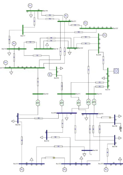
The system used throughout the thesis was the 1996 IEEE one area 24 bus reliability test system (RTS) [12]. The system is shown in Figure 3.1 on page 16, where the top portion of the system is the medium voltage area and the bottom is the low voltage area. The system contains 38 branches with some duplicate branches, five transformers connecting the medium and low voltage areas, 17 bus loads, and 33 generators, including a synchronous condenser at bus 14.
3.2 IEC 60870-5-104 Protocol
The IEC 60870-5-104 (IEC 104) protocol is used in the electric utilities industry, pri-marily in Europe, Middle East, and Asia Pacific. The protocol is an extension of the application layer in the IEC 60870-5-101 protocol allowing for communication over TCP/IP using port 2404 on the server. IEC 104 contains different methods of
16 CHAPTER3. METHODOLOGY
Figure 3.1: 1996 IEEE 24 bus RTS
3.2. IEC 60870-5-104 PROTOCOL 17
requested information. The cyclic data transmission is when the field devices are configured to send data periodically without being requested to. The acquisition of events method allows data to be sent to the client when events occur on the server, such as failures. These data acquisition methods are identified in the cause of trans-mission field in the IEC 104 messages, which will be explained later on.
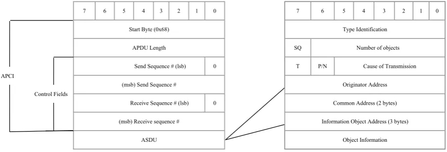
An IEC 104 message is made up of the Application Protocol Data Unit (APDU), which contains the Application Protocol Control Information (APCI) and Application Service Data Unit (ASDU). The APCI contains the start byte, length, and four control fields, which are explained as follows:
Start byte: One byte long and indicates the start of an IEC 104 message with the hexadecimal value 0x68.
Length: One byte long and indicates the length of the APDU without the start byte and this field.
Control fields: Four bytes long and is used to determine the format of the APCI, and contains sequence numbers. This firewall in this thesis inspects the control field when an IEC 104 packet is received to determine whether more fields need to be inspected.
The third byte in the APCI, which is the first control byte, determines whether or not an ASDU is transmitted along with the APCI. Inside this byte the first and second bit determine the the format of the APCI. If the first bit is 0 then the APCI is in information format (I-format), as shown in Figure 3.2.
7 6 5 4 3 2 1 0
Start Byte (0x68)
APDU Length
Send Sequence # (lsb) 0
(msb) Send Sequence #
Receive Sequence # (lsb) 0
(msb) Receive sequence #
ASDU
7 6 5 4 3 2 1 0
Type Identification
SQ Number of objects
T P/N Cause of Transmission
Originator Address
Common Address (2 bytes)
Information Object Address (3 bytes)
Object Information Control Fields
[image:29.595.104.564.463.619.2]APCI
Figure 3.2: IEC 104 APCI I-Format with ASDU
18 CHAPTER3. METHODOLOGY
fixed at four bytes, but when the APDU contains the APCI and the ASDU then the length field will be greater than four and a maximum of 253 bytes. The I-format APCI contains sequence numbers in the control fields for both sent and received data which are used for transmission confirmations.
7 6 5 4 3 2 1 0
Start Byte (0x68)
APDU Length
Send Sequence # 0 1
0
Receive Sequence # 0
[image:30.595.146.425.166.304.2]Receive Sequence #
Figure 3.3:APCI S-Format
7 6 5 4 3 2 1 0
Start Byte (0x68)
APDU Length
TESTFR STOPDT STARTDT
1 1
con act con act con act
0
0 0
0
Figure 3.4: APCI U-Format
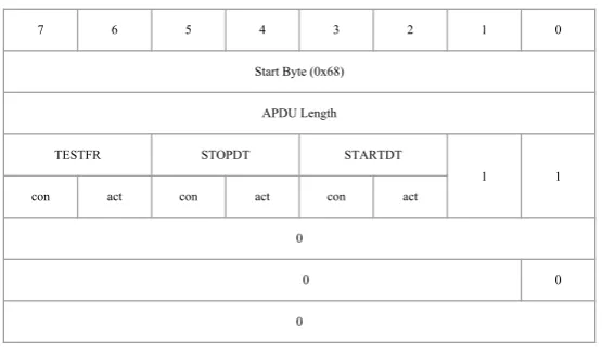
[image:30.595.146.424.356.518.2]3.2. IEC 60870-5-104 PROTOCOL 19
the controlling station and confirmed by the controlled station before any user data transfer from the controlled station is initiated.
The ASDU, format shown in Figure 3.2, is used to send application data and consists of the following fields: type identification, variable structure qualifier, cause of transmission, originator address, common address (ASDU address fields), infor-mation object address, and object inforinfor-mation fields. A description of these fields is as follows.
Type Identification: One byte and indicates the type of information object sent which can include a time tag (timestamp) that is three bytes. 256 possible values, but 0 is invalid, 128-135 are reserved for routing messages, 136-255 are for special use. Only 1-127 are defined in the standard. Type Identification defines the structure, type and format of the information object.
Variable Structure Qualifier: One byte and is comprised of the SQ bit and the number of objects.
• SQ:One bit and indicates whether information objects are single (0) or a
se-quence (1) of information elements. With single, the information element is addressed by the Information Object Address, and each information object has an address associated with it. With sequence, the Information Object Ad-dress specifies the adAd-dress of the first information element, and the following information elements are identified by an increment of 1 starting from the first address for each element.
• Number of objects: Seven bits and indicates number of information objects
Cause of Transmission: One byte and indicates the data acquisition method. Contains T, P/N bits.
• T: One bit and indicates if ASDU was generated during testing (1) conditions
or not (0)
• P/N:One bit and indicates positive (0) or negative (1) confirmation of a request • Cause: Six bits and indicates specific reason for transmissions, such as
peri-odic, requested, etc. Zero is not defined and only 1-13 and 20-41 are defined. Originator Address: One byte and used when a host is relaying a message to other hosts or when directing mirrored ASDUs in monitor direction (Server →
Client). The relaying host would use this field to identify the original sender. Field is zero when not relaying messages.
20 CHAPTER3. METHODOLOGY
Information Object Address: Three bytes and indicates the address of the requested object. If address is not relevant (not used) then it is set to zero. Each requested information object has an address. Used as destination address in control direction (Client →Server), and as source address in the monitor direction (Server →Client).
Object Information: Variable size depending on the Type Identification. Con-tains the actual data.
In answering the research questions and developing the tools used for testing, the IEC 104 protocol fields were utilized.
3.3 Critical components of an ICS system
[image:32.595.188.383.565.685.2]Two different methods for determining critical components within the IEEE 24 bus system were used. These methods were (i) minimum and maximum connections to other buses, and (ii) finding correlations between branch powers and using one of the buses attached to those branches. Using buses with minimum and maximum number of connections was a way to see how the firewall would perform if it knew the state of components with a certain amount of connections in the system. For instance, how would the results compare if the firewall knew the states of buses with three connections versus buses with 5 connections. The initial hypothesis was that observing buses with greater number of connections would result in the firewall being able to better filter out malicious traffic, but in some ways this was not the case as will be shown in the Results section.Table 3.1 shows the number of connections and the buses that had that number of connections. For example bus 7 only had one connection to another bus, while buses 9, 10, and 21 had connections to 5 other buses each.
Table 3.1: Bus connections Connections Buses
1 7
2 4,5,6,14,22,24
3 1,2,3,8,13,17,18,19 4 11,12,15,16,20,23
5 9,10,21
3.4. MODELING THE CRITICAL COMPONENTS IN THE FIREWALL 21
24 bus system were collected as different actions were taken in the system. These actions were activating, deactivating switches and increasing, decreasing bus load power. The data was collected using the IEEE 24 bus case MatLab file in [14], which is the format needed to be used with Matpower. A script, located at [15], was created using MATLAB which took commands corresponding to the actions mentioned (ac-tivate switch, deac(ac-tivate switch, increase load, and decrease load). Once an action was taken an AC power flow analysis was done using using Matpower to determine the effect of the action on the system. The branch powers from the result of the power flow is used to determine if there are any correlations between the branch powers.
After collecting the branch real power data the MATLAB function ‘corrcoef’ was used to obtain the correlation coefficient matrix between all the branches. The re-sulting correlation coefficient matrix, located in [16] under the “Orig branch power coefficient” tab, was used to help determine which branches were correlated. One of the two buses which makes up the branch was chosen based on trying to minimize the number of components that needed to be observed. After choosing branches considered as critical components, we made graphs, where the branch with the cho-sen bus was on the x-axis and the branch it correlated with was on the y-axis, along with a linear regression line. The code to generate the linear regression equations is in [17]. The graphs and the linear regression equations are shown and talked about in more detail in Chapter 4. The linear regression equation was in the form of y = Ax + B, where x is the branch with the critical component and y is the branch that has a strong correlation with the branch containing the critical component. The linear regression equations were incorporated into the model developed to determine the branch power of the branch that correlated to the branch with critical component.
3.4 Modeling the Critical Components in the Firewall
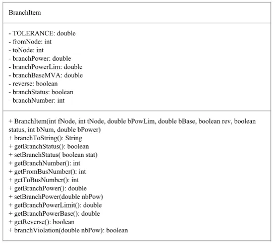
A model of the components to be created was made using Java, where the different components in the IEEE 24 bus system were divided into different classes. Each component such as a bus, load, branch, and generator had a class associated with it. Figures 3.5 to 3.8 show the classes for the branches, loads, generators, and buses named BranchItem, LoadItem, GeneratorItem, and BusItem respectively.
Each class contains values for the components, such as limit constraints, as well as values that change over time such as the power in the component. Each class is explored in a bit more detail below, but the functions will be not explained in detail as they are available at [18].
22 CHAPTER3. METHODOLOGY
LoadItem
- loadPower: double - loadPowerBase: double
+ LoadItem(double power, double lpBase) + LoadItem(double power)
[image:34.595.182.391.89.193.2]+ getLoadPower(): double + getLoadBase(): double + setLoadPower(double power)
Figure 3.5: LoadItem classes with variables and methods
the power base respectively. The power base in the IEEE 24 bus system is 100 MVA, but for other systems this could change so this value is kept track of. There are two constructors for the class both taking in the power, and one allowing the inclusion of a power base. If the power base is not passed in it defaults to 100 MVA. The remaining classes are get and set methods for getting the power base and power value and for setting the power of the load respectively.
BranchItem
- TOLERANCE: double - fromNode: int - toNode: int - branchPower: double - branchPowerLim: double - branchBaseMVA: double - reverse: boolean - branchStatus: boolean - branchNumber: int
+ BranchItem(int fNode, int tNode, double bPowLim, double bBase, boolean rev, boolean status, int bNum, double bPower)
+ branchToString(): String + getBranchStatus(): boolean + setBranchStatus( boolean stat) + getBranchNumber(): int + getFromBusNumber(): int + getToBusNumber(): int + getBranchPower(): double + setBranchPower(double nbPow) + getBranchPowerLimit(): double + getBranchPowerBase(): double + getReverse(): boolean
+ branchViolation(double nbPow): boolean
Figure 3.6: BranchItem classes with variables and methods
[image:34.595.149.422.366.608.2]3.4. MODELING THE CRITICAL COMPONENTS IN THE FIREWALL 23
where it is included and this is to increase the range of limits by a small value. The TOLERANCE was chosen to be 0.01 to correct error differences between decimal precisions in JAVA and MATLAB. Other TOLERANCE values could be used such as having it be 10% of the component value to allow for larger error corrections, but differing TOLERANCE values were not investigated as part of this thesis. With the TOLERANCE value added the limit constraints are as follows:
Limitmin−T OLERAN CE≤V alueactual≤Limitmax+T OLERAN CE (3.1) A version of equation 3.1 is also used to check for violations within each compo-nent. The constructor of the class takes in all the values needed to set the variables mentioned. The remaining functions are get and set functions along with a branchVi-olation function. The branchVibranchVi-olation function does a simple check for power limit violations on the branch as expressed in equation 3.2.
|P oweractual| ≤LimitBranchP ower+T OLERAN CE (3.2)
BusItem
- TOLERANCE: double - busNum: int - voltageValue: double - baseKV: double - hasLoad: boolean - iLoad: LoadItem - hasGen: boolean
- multiGen: List<GeneratorItem> - branches: List<BranchItem> - maxVoltage: double - minVoltage: double
+ BusItem(BustItem bi)
+ copyBranches(List<BranchItem> b): List<BranchItem> + copyGenerators(List<GeneratorItem> g): List<GeneratorItem>
+ BusItem(int bnum, double voltVal, double maxVolt, double minVolt, double basekv) + BusItem(int bnum, double voltVal, LoadItem iload, double maxVolt, double minVolt, double basekv)
+ BusItem(int bnum, double voltVal, GeneratorItem gen, double maxVolt, double minVolt, double basekv)
+ BusItem(int bnum, double voltVal, LoadItem iload, GeneratorItem gen, double maxVolt, double minVolt, double basekv)
+ addGenerators(GeneratorItem gen) + addBranch(BranchItem bran) + getBranches(): List<BranchItem> + getBranch(int bIndx): BranchItem + setBranchPower(int bIndx, double bPower) + setBranchStatus(int bIndx, boolean stat) + addLoad(LoadItem ld)
+ setVoltage(double volt)
+ setGeneratorValue(double gValue, double gqValue, int genIndx) + getBusNum(): int
+ getVoltage(): double + getVoltageBase(): double + getHasLoad(): boolean + getLoadItem(): LoadItem + getHasGen(): boolean
+ getGeneratorItems(): List<GeneratorItem> + getGenerator(int gindx): List<GeneratorItem> + getMaxVoltage(): double
+ getMinVoltage(): double + voltViolation(double Volt): boolean
LoadItem
- loadPower: double - loadPowerBase: double
+ LoadItem(double power, double lpBase) + LoadItem(double power)
+ getLoadPower(): double + getLoadBase(): double + setLoadPower(double power) GeneratorItem
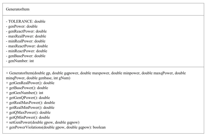
- TOLERANCE: double - genPower: double - genReactPower: double - maxRealPower: double - minRealPower: double - maxReactPower: double - minReactPower: double - genBasePower: double - genNumber: int
+ GeneratorItem(double gp, double gqpower, double maxpower, double minpower, double maxqPower, double minqPower, double genbase, int gNum)
+ getGenRealPower(): double + getBasePower(): double + getGenNumber(): int + getGenQPower(): double + getRealMaxPower(): double + getRealMinPower(): double + getQMaxPower(): double + getQMinPower(): double
+ setGenPower(double gpow, double gqpow)
+ genPowerViolations(double gpow, double gqpow): boolean
BranchItem
- TOLERANCE: double - fromNode: int - toNode: int - branchPower: double - branchPowerLim: double - branchBaseMVA: double - reverse: boolean - branchStatus: boolean - branchNumber: int
+ BranchItem(int fNode, int tNode, double bPowLim, double bBase, boolean rev, boolean status, int bNum, double bPower) + branchToString(): String
+ getBranchStatus(): boolean + setBranchStatus( boolean stat) + getBranchNumber(): int + getFromBusNumber(): int + getToBusNumber(): int + getBranchPower(): double + setBranchPower(double nbPow) + getBranchPowerLimit(): double + getBranchPowerBase(): double + getReverse(): boolean
+ branchViolation(double nbPow): boolean SystemModel
- violations: boolean - SUCCESS: int - log: Logger - catchViolations: int
- linRegression: Map<String, List<String[]>>
+ getResults(int packetsProcessed, int packetsAllowed, int packetsRejected, boolean[] packStat) + setLogging()
+ printBus(Map<Integer,BusItem> buses, double[][] criticalComps) + copyFiles(String file, String dst)
+ formattedDecimal(double dig): double
+ runUpdate(Map<Integer, BusItem> buses, MatlabTypeConverter processor, MatlabProxy proxy, double[][] criticalComps): Map<Integer, BusItem>
+ updateModel(Map<Integer, BusItem> tempBuses, double[][] loadRes, double[][] genRes, double branchRes): boolean + initBranches(MatlabTypeConverter processor, Map<Integer, BusItem> buses)
+ initCase(MatlabTypeConverter processor, MatlabProxy proxy): Map<Integer, BusItem> + copyMap(Map<Integer, BusItem> hm): Map<Integer, BusItem>
+ checkLinRegression(String predictorBranch, double predictorPower, double predictorPowerBase): boolean + relations(String brString, String predBranch, String predLimit, String slope, String intercept)
[image:35.595.140.489.297.524.2]+ populateLinRegression()
Figure 3.7: GeneratorItem classes with variables and methods
GeneratorItem Class:The GeneratorItem class also has the TOLERANCE vari-able along with varivari-able to store the generator real and reactive power, the minimum and maximum real and reactive power allowed, the power base, and the generator number. In the matpower case files a single bus can have multiple generators and so the generator number is used to store which generator is represented. The con-structor for the classes takes in parameters to initialize all the variables in the class mentioned. The remaining functions are get and set functions. The set function in the class takes two parameters which represent the real and reactive power and is used to update those values as every time the model is updated. There is a gener-ator power violation function which checks to make sure that the both the real and reactive powers are within the allowed limits. The checks used is as follows:
24 CHAPTER3. METHODOLOGY
ReactP owermin−T OLERAN CE≤ReactP oweractual≤ReactP owermax+T OLERAN CE (3.4)
If any of the checks fail then the function returns a boolean true value to alert the model driver program of the violation.
BusItem
- TOLERANCE: double - busNum: int - voltageValue: double - baseKV: double - hasLoad: boolean - iLoad: LoadItem - hasGen: boolean
- multiGen: List<GeneratorItem> - branches: List<BranchItem> - maxVoltage: double - minVoltage: double
+ BusItem(BustItem bi)
+ copyBranches(List<BranchItem> b): List<BranchItem> + copyGenerators(List<GeneratorItem> g): List<GeneratorItem>
+ BusItem(int bnum, double voltVal, double maxVolt, double minVolt, double basekv) + BusItem(int bnum, double voltVal, LoadItem iload, double maxVolt, double minVolt, double basekv)
+ BusItem(int bnum, double voltVal, GeneratorItem gen, double maxVolt, double minVolt, double basekv)
+ BusItem(int bnum, double voltVal, LoadItem iload, GeneratorItem gen, double maxVolt, double minVolt, double basekv)
+ addGenerators(GeneratorItem gen) + addBranch(BranchItem bran) + getBranches(): List<BranchItem> + getBranch(int bIndx): BranchItem + setBranchPower(int bIndx, double bPower) + setBranchStatus(int bIndx, boolean stat) + addLoad(LoadItem ld)
+ setVoltage(double volt)
+ setGeneratorValue(double gValue, double gqValue, int genIndx) + getBusNum(): int
+ getVoltage(): double + getVoltageBase(): double + getHasLoad(): boolean + getLoadItem(): LoadItem + getHasGen(): boolean
+ getGeneratorItems(): List<GeneratorItem> + getGenerator(int gindx): List<GeneratorItem> + getMaxVoltage(): double
+ getMinVoltage(): double + voltViolation(double Volt): boolean
LoadItem
- loadPower: double - loadPowerBase: double
+ LoadItem(double power, double lpBase) + LoadItem(double power)
+ getLoadPower(): double + getLoadBase(): double + setLoadPower(double power) GeneratorItem
- TOLERANCE: double - genPower: double - genReactPower: double - maxRealPower: double - minRealPower: double - maxReactPower: double - minReactPower: double - genBasePower: double - genNumber: int
+ GeneratorItem(double gp, double gqpower, double maxpower, double minpower, double maxqPower, double minqPower, double genbase, int gNum)
+ getGenRealPower(): double + getBasePower(): double + getGenNumber(): int + getGenQPower(): double + getRealMaxPower(): double + getRealMinPower(): double + getQMaxPower(): double + getQMinPower(): double
+ setGenPower(double gpow, double gqpow)
+ genPowerViolations(double gpow, double gqpow): boolean
BranchItem
- TOLERANCE: double - fromNode: int - toNode: int - branchPower: double - branchPowerLim: double - branchBaseMVA: double - reverse: boolean - branchStatus: boolean - branchNumber: int
+ BranchItem(int fNode, int tNode, double bPowLim, double bBase, boolean rev, boolean status, int bNum, double bPower) + branchToString(): String
+ getBranchStatus(): boolean + setBranchStatus( boolean stat) + getBranchNumber(): int + getFromBusNumber(): int + getToBusNumber(): int + getBranchPower(): double + setBranchPower(double nbPow) + getBranchPowerLimit(): double + getBranchPowerBase(): double + getReverse(): boolean
+ branchViolation(double nbPow): boolean SystemModel
- violations: boolean - SUCCESS: int - log: Logger - catchViolations: int
- linRegression: Map<String, List<String[]>>
+ getResults(int packetsProcessed, int packetsAllowed, int packetsRejected, boolean[] packStat) + setLogging()
+ printBus(Map<Integer,BusItem> buses, double[][] criticalComps) + copyFiles(String file, String dst)
+ formattedDecimal(double dig): double
+ runUpdate(Map<Integer, BusItem> buses, MatlabTypeConverter processor, MatlabProxy proxy, double[][] criticalComps): Map<Integer, BusItem>
+ updateModel(Map<Integer, BusItem> tempBuses, double[][] loadRes, double[][] genRes, double branchRes): boolean + initBranches(MatlabTypeConverter processor, Map<Integer, BusItem> buses)
+ initCase(MatlabTypeConverter processor, MatlabProxy proxy): Map<Integer, BusItem> + copyMap(Map<Integer, BusItem> hm): Map<Integer, BusItem>
+ checkLinRegression(String predictorBranch, double predictorPower, double predictorPowerBase): boolean + relations(String brString, String predBranch, String predLimit, String slope, String intercept)
[image:36.595.143.424.176.573.2]+ populateLinRegression()
Figure 3.8:BusItem class with variables and methods
3.4. MODELING THE CRITICAL COMPONENTS IN THE FIREWALL 25
The BusItem class contains several constructors which all atleast take in param-eters which are for the bus number, the voltage value, the maximum and minimum voltage allowed, and the voltage base. The constructors differ based on whether the bus has a load or generators or both. There are functions to add generators to the bus in case more generators are added later on and also to add branches and loads. The remaining functions are get and set functions to retrieve values and to set bus voltage, branch, generator, and load power. There is also a voltage violation function for verifying that the bus voltage is within the range of allowed values. The check used to check the bus voltage value was as follows:
V oltagemin−T OLERAN CE≤V oltageactual≤V oltagemax+T OLERAN CE (3.5)
If this check is violated a boolean true value is sent to the driver program to indicate that a bus violation has occurred.
The component models were created in this way to allow for a modular design for future work where new components could be added, such as transformers. Each component contains only the necessary data to know its states and the ability to view and update that data quickly.
BusItem
- TOLERANCE: double - busNum: int - voltageValue: double - baseKV: double - hasLoad: boolean - iLoad: LoadItem - hasGen: boolean
- multiGen: List<GeneratorItem> - branches: List<BranchItem> - maxVoltage: double - minVoltage: double
+ BusItem(BustItem bi)
+ copyBranches(List<BranchItem> b): List<BranchItem> + copyGenerators(List<GeneratorItem> g): List<GeneratorItem>
+ BusItem(int bnum, double voltVal, double maxVolt, double minVolt, double basekv) + BusItem(int bnum, double voltVal, LoadItem iload, double maxVolt, double minVolt, double basekv)
+ BusItem(int bnum, double voltVal, GeneratorItem gen, double maxVolt, double minVolt, double basekv)
+ BusItem(int bnum, double voltVal, LoadItem iload, GeneratorItem gen, double maxVolt, double minVolt, double basekv)
+ addGenerators(GeneratorItem gen) + addBranch(BranchItem bran) + getBranches(): List<BranchItem> + getBranch(int bIndx): BranchItem + setBranchPower(int bIndx, double bPower) + setBranchStatus(int bIndx, boolean stat) + addLoad(LoadItem ld)
+ setVoltage(double volt)
+ setGeneratorValue(double gValue, double gqValue, int genIndx) + getBusNum(): int
+ getVoltage(): double + getVoltageBase(): double + getHasLoad(): boolean + getLoadItem(): LoadItem + getHasGen(): boolean
+ getGeneratorItems(): List<GeneratorItem> + getGenerator(int gindx): List<GeneratorItem> + getMaxVoltage(): double
+ getMinVoltage(): double + voltViolation(double Volt): boolean
LoadItem
- loadPower: double - loadPowerBase: double
+ LoadItem(double power, double lpBase) + LoadItem(double power)
+ getLoadPower(): double + getLoadBase(): double + setLoadPower(double power) GeneratorItem
- TOLERANCE: double - genPower: double - genReactPower: double - maxRealPower: double - minRealPower: double - maxReactPower: double - minReactPower: double - genBasePower: double - genNumber: int
+ GeneratorItem(double gp, double gqpower, double maxpower, double minpower, double maxqPower, double minqPower, double genbase, int gNum)
+ getGenRealPower(): double + getBasePower(): double + getGenNumber(): int + getGenQPower(): double + getRealMaxPower(): double + getRealMinPower(): double + getQMaxPower(): double + getQMinPower(): double
+ setGenPower(double gpow, double gqpow)
+ genPowerViolations(double gpow, double gqpow): boolean
BranchItem
- TOLERANCE: double - fromNode: int - toNode: int - branchPower: double - branchPowerLim: double - branchBaseMVA: double - reverse: boolean - branchStatus: boolean - branchNumber: int
+ BranchItem(int fNode, int tNode, double bPowLim, double bBase, boolean rev, boolean status, int bNum, double bPower) + branchToString(): String
+ getBranchStatus(): boolean + setBranchStatus( boolean stat) + getBranchNumber(): int + getFromBusNumber(): int + getToBusNumber(): int + getBranchPower(): double + setBranchPower(double nbPow) + getBranchPowerLimit(): double + getBranchPowerBase(): double + getReverse(): boolean
+ branchViolation(double nbPow): boolean SystemModel
- violations: boolean - SUCCESS: int - log: Logger - catchViolations: int
- linRegression: Map<String, List<String[]>>
+ getResults(int packetsProcessed, int packetsAllowed, int packetsRejected, boolean[] packStat) + setLogging()
+ printBus(Map<Integer,BusItem> buses, double[][] criticalComps) + copyFiles(String file, String dst)
+ formattedDecimal(double dig): double
+ runUpdate(Map<Integer, BusItem> buses, MatlabTypeConverter processor, MatlabProxy proxy, double[][] criticalComps): Map<Integer, BusItem>
+ updateModel(Map<Integer, BusItem> tempBuses, double[][] loadRes, double[][] genRes, double branchRes): boolean + initBranches(MatlabTypeConverter processor, Map<Integer, BusItem> buses)
+ initCase(MatlabTypeConverter processor, MatlabProxy proxy): Map<Integer, BusItem> + copyMap(Map<Integer, BusItem> hm): Map<Integer, BusItem>
+ checkLinRegression(String predictorBranch, double predictorPower, double predictorPowerBase): boolean + relations(String brString, String predBranch, String predLimit, String slope, String intercept)
[image:37.595.138.487.372.586.2]+ populateLinRegression()
Figure 3.9: Main model driver program
26 CHAPTER3. METHODOLOGY
would like the model to take note of, and a variable which stores branches and the branches that they correlate with along with the linear regression equations.
[image:38.595.75.502.325.374.2]The Main program of the model driver gets messages, from the simulated firewall through a socket, which contains the command that is in the packet along with the value. The commands are restricted to process commands, certain Type Identifica-tions, in the IEC 104 protocol only as those are the commands that will be directly affecting the components. In this thesis only three process commands were con-sidered, which are “Single command”, “Double command”, and “Setpoint command scaled value”. These commands can be with or without the CP56Time2a time tag. The process commands and their Type Identification are shown in Table 3.2 along with the information object element types that are associated with them.
Table 3.2: Process commands with type identification and information object ele-ments.
Command Type Identification Information Object Element Information Single Command (w/ time tag) 45 (58) SCO - 1 byte, (CP56Time2a - 7 bytes) Double Command (w/ time tag) 46 (59) DCO - 1 byte, (CP56Time2a - 7 bytes)
Setpoint Command Scaled Value (w/ time tag) 49 (62) SVA - 2 bytes, QOS - 1 byte, (CP56Time2a - 7 bytes)
The firewall only sends the command, value, and information object address, which indicates which component to target, to the model driver if the IEC 104 packet has the type identifications in Table 3.2; as well as having a Cause of Transmission of 6 or 8 along with the S/E bit set to 0 meaning to execute. A Cause of Transmission of 6 or 8 indicates that the command is going towards the process component rather than being a response from a previous command, as specified in the IEC 60870-5-104 standard. Once the command and value, which is stored in the SCO, DCO, or SVA information element (c.f Table 3.2, is received by the driver program, the value is sent to a MATLAB program along with the critical components list where a power flow analysis is ran. For instance, if the command received is a single command with a value of 0, indicating to turn off, and the information object address is for a branch then the MATLAB program will perform the power flow analysis with the indicated branch set to inactive. Once the power flow analysis is completed the new values for the critical components are sent back to the SystemModel program where the critical components models are then updated and checked for violations.
3.5. IDENTIFYINGCHANGES INICS SYSTEMDUE TOTRAFFIC 27
as well as the MATLAB scripts used can be viewed at [19].
3.5 Identifying Changes in ICS System Due to Traffic
In order to determine if a packet will make changes to components in the ICS sys-tem, the Type Identification of the IEC 104 ASDU had to be examined. The Type Identifications that directly change the process components, in addition to those mentioned in the 3.2, include: regulating step, set point normalized, setpoint floating point number, and bitstring of 32 bits commands. As mentioned, this thesis consid-ers only the three commands, single, double, and setpoint scaled value command, to signify that the packet will be changing a component. Any other commands that are not process commands can be handled differently by the firewall using whitelist-ing but this is implemented in this thesis. If durwhitelist-ing inspection of a packet the firewall determines that the packet has a destination port of 2404 and contains an ASDU with a type identification that matches that of a process command then the cause of transmission along with the information object information is inspected. Figure 3.10 shows the fields within the ASDU that are inspected if the type identification is for a single command. After verifying that both the type identification and the cause of transmission, the “S/E” bit is the final check in order to determine whether to send the packet to the model for testing. The S/E bit is for select (1) and execute (0), and it has to be set to execute in order to send it to the model. If the S/E bit is set to select than it means that the component is being prepared and the packet will not actually do anything to change the component or the system. The SCS bit for single commands is set to 0 for turning a component off and 1 for turning the component on. This value would be sent along with the IOA and a string indicating the command to the model.
Once the packet has been sent to the model program then the determination of whether to allow or reject the packet is as described in the previous section. The variable structure identifier in the ASDU for the process commands always have a value of “1” since only a single information will be sent.
3.6 Test Setup
28 CHAPTER3. METHODOLOGY
7 6 5 4 3 2 1 0
0 0 1 0 1 1 0 1
0 0 0 0 0 0 0 1
0 0 0 0 0 1 1 0
0 0 0 0 0 0 0 0
0 0 0 0 0 0 1 1
0 0 0 0 0 0 0 0
0 0 1 1 1 1 1 1
0 0 0 0 0 0 0 0
0 0 0 0 0 0 0 0
0 0 0 0 0 0 0 0 IOA
Common Address Originator Address
COT Variable Structure Identifier
Type Identification
SCO
[image:40.595.156.419.86.331.2]SCO => S/E QU 0 SCS
Figure 3.10: ASDU with fields that are inspected to determine if packet information is sent to model
#12 and #14 respectively. The order that the commands were given is shown in the “#” columns and the commands with red backgrounds indicates commands that resulted in either voltage violations or branch power violations or both. The data associated with each command can be seen in the excel sheet in [16], under the “Origtest volt” and “Origtest branch power” sheets.
Table 3.3: Command Sequence A. Commands with red background indicate viola-tions occurred.
# Command # Command # Command # Command # Command # Command 1 load 1 .5 11 load 4 1.392 21 cutoff 9 4 0 31 load 14 1.803 41 cutoff 19 20 0 51 cutoff 22 17 1 2 cutoff 2 4 0 12 cutoff 9 8 1 22 cutoff 9 8 0 32 cutoff 14 11 0 42 cutoff 13 23 0 52 load 19 1.2006 3 cutoff 9 8 0 13 load 8 1.497 23 load 1 1.296 33 load 18 1.4008 43 cutoff 22 17 0 53 load 4 0.7961 4 load 9 1.097 14 cutoff 10 8 0 24 load 3 1.4 34 load 9 .802 44 cutoff 19 20 1 54 load 8 1.1992 5 cutoff 10 5 0 15 cutoff 21 22 1 25 cutoff 3 24 0 35 load 1 1.5 45 cutoff 21 15 0 55 cutoff 21 15 1 6 cutoff 16 15 0 16 load 20 1.5 26 load 14 1.199 36 cutoff 16 15 1 46 load 3 1.4006 56 cutoff 7 8 0 7 load 19 1.099 17 cutoff 23 20 0 27 cutoff 16 15 1 37 cutoff 10 5 1 47 load 15 1.2 57 load 1 1.4 8 load 18 1.498 18 load 10 1.4 28 cutoff 1 3 1 38 cutoff 10 8 1 48 load 19 1.2014 58 cutoff 13 11 0 9 cutoff 21 22 0 19 load 14 1.397 29 load 3 1.2976 39 load 15 1.4984 49 load 9 1.2987 59
10 cutoff 1 3 0 20 cutoff 17 16 0 30 cutoff 3 24 0 40 load 19 1.39698 50 load 2 1.2989 60
[image:40.595.66.502.544.672.2]3.6. TESTSETUP 29
as “cutoff [from bus] [to bus] [status]”. Status is either 0 for deactivation or 1 for activation. The MATLAB script used to enter and run these commands is in [15].
After the commands and their data is verified in MATLAB, they are translated to fit into the IEC 104 protocol format using an open source IEC 104 packet gen-erator [21]. The packet gengen-erator contains client and server programs where the commands are sent from the client to the server and the server echoes the clients commands back. After a few modifications to the Python files the commands were written in the “ieee 24 traffic.py” file [22]. The commands are in the following format:
(‘START’, ‘auto’, ‘if’, [TI, VSQ, CoT, OA, CA, (IOA, IOA information)])
An example for the first command “load 1 .5” is as follows:
(‘START’, ‘auto’, ‘if’, [49, 1, Cause_Act, 0, 3, (25, 54, QOS_Ex)])
The Originator Address (OA) is set to 0 to indicate that there are no relays being used, and the Common Address (CA) was arbitrarily chosen to be 3. The Origina-tor and Common addresses were the same for all the packets generated. The Type Identification (TI) used for the load command is 49 which is thesetpoint scaled value
command and the variable structure qualifier (VSQ) is set to 1 since there will only be a single information object. The “Cause Act” value is a variable which is set to 0x06 to indicate an activation Cause of Transmission (CoT). The Information Ob-ject Address (IOA) is set to 25, to indicate bus 1, which is a value that was chosen based on a configuration file created, c.f. “ieee24 iec.properties”[19], where each component is given an address. The SVA value for the setpoint scale value com-mand is 54 since the previous load power at bus 1, 108 MW, is now multiplied by .5, so the load power will be decreased by half. QOS Ex, set to 0x00, is a variable to indicate that the packet will be executed since the S/E bit will be set to 0. After the commands were created both the client and server programs were started along with the network monitor program CommView 6.5. The CommView program allowed for capturing the traffic between the client and the server on the loopback interface as both were running on the same computer. Once the client finished sending all the commands to the server the network capture was stopped and a pcapng file, “ieee 24 traffic.pcapng” [22] was created for later use in testing the model.
30 CHAPTER3. METHODOLOGY ASDU info Extraction Python Packet Java MATLAB Powerflow Analysis cutoff Load Increase Violation Occurred? Check Violations Command Translation Packet Status Allow Reject Update Component Model Yes/No No Observed Component Model Command Select
[image:42.595.67.504.93.343.2]Firewall Model ICS System
Figure 3.11: Interactions between firewall, model, and ICS system
where the correct scripts to be executed in MATLAB are chosen based on the com-mand. The MATLAB scripts get executed with the extracted information from the packets and a power flow analysis is ran. The data for the critical components being observed from the power flow analysis is related back to the system model where violations on both the observed components and the components which they may have a correlation to are checked. If no violations occur the model is updated. The system model then sends back the results to the firewall indicating whether the packet should be rejected or allowed through.
Since results of the command executions are known beforehand, from Table 3.3, the false positive and negative rates can be calculated, as well as the accuracy of the entire model and firewall in helping to filter out the packets that are considered malicious. The false positive and negative rates, along with the accuracy of the entire system are explored in chapter 4.
3.7 Discussion
connec-3.7. DISCUSSION 31
tions method can lead to the firewall allowing the packet through unless there are violations on the observed components. Finding valid correlations between compo-nents would help to determine the state of compocompo-nents that are not being observed by using the values of those components that are observed and are correlated with the unobserved component. As mentioned, in this thesis the correlations were only focused on the branch real powers but correlations on bus voltages and generator real and reactive powers could also be tested for to create a better model. This method of finding correlations between components to determine critical compo-nents could potentially be applied to other ICS systems as well such as water and waste management, and chemical processing plants.
The model created allows for simple definitions of components as well as for fu-ture additions of components should they be needed, such as the addition of trans-formers. The checks for violations within the model are currently only on the single component values, power or voltage value, compared against the constraints placed on the component. Other checks could be incorporated such as those in [20], which include using Kirchoff’s current law to check that the current going into a bus is approximately the same as the current leaving the bus.
Chapter 4
Results
This chapter discusses results obtained from two test runs, explained in the follow-ing. Section 4.1 focuses on the correlations found between branch powers and the linear regression equations formed. Section 4.2 focuses on the firewall results of the Sequence A commands in Table 3.3 of section 3.6. Section 4.3 will focus on the firewall results based on a different set of commands, Sequence B, but using the same linear regression equations show in Figure 4.1 of Section 4.1.
4.1 Correlation Results From Command Sequence A
Using the data from the power flow analysis gathered after running command Se-quence A commands, the correlation coefficients were calculated using MATLAB, as explained in section 3.3, the results of which are in [16]. From those coefficients sev-eral buses were chosen to be the critical components due to them being connected to a branch having strong relationship with another branch.
Other buses were also chosen if they were connected to a branch that had very weak relationships with other branches. For example, the branch connecting bus 7 and 8, had a correlation coefficient of 0 with other branches. The buses chosen in-cluded buses 1,2,3,7,9,10,16,21, and 23. These buses were chosen after reviewing the correlation coefficients in [16] under the “Orig branch power coefficient” tab. With these buses all of the branches in the IEEE 24 bus system could be observed either due to the bus being connected directly to a branch or being connected to a branch that it correlates to. Figure 4.1 shows the graphs of branches that contain some of the buses and the branches that they correlated with. The X-axis represents the first branch and the Y-axis represents the second branch. For example with Figure 4.1a, the X-axis represents branch 16-17, and the Y-axis represents branch 18-17. The linear regression equation is also represented in the graph. The code used to generate these graphs can be found in [17].
34 CHAPTER4. RESULTS
(a) (b)
(c) (d)
(e) (f)
[image:46.595.120.446.84.719.2](g)
![Figure 2.1: ICS vulnerability, exploit, and malware count per year [24]](https://thumb-us.123doks.com/thumbv2/123dok_us/9726741.473669/18.595.79.501.88.399/figure-ics-vulnerability-exploit-malware-count-year.webp)
![Figure 2.2: ISA-99 Purdue Model [33]](https://thumb-us.123doks.com/thumbv2/123dok_us/9726741.473669/19.595.93.536.414.737/figure-isa-purdue-model.webp)