Creating a toolkit for human robot interaction
J. (Jens) Oosterkamp
MSc Report
Committee:
Prof.dr.ir. S. Stramigioli
Dr.ir. E. Dertien
Dr.ir. J.F. Broenink
Dr.ir. D. Reidsma
Creating a toolkit for human robot interaction
J. Oosterkamp
iii
Summary
New commercial fields of robotics are emerging, in which the robot’s ability to interact with humans is a requirement. One of the focuses of this project is bridging the gap between ’pro-grammers’ and ’robot builders’. More specific, the Human Media Interaction (HMI) group of University of Twente is looking for a robotic platform on which they can apply their human-robot interaction software, AsapRealizer [1]. In this research the design space of a minimalistic robot is mapped and a software toolkit is built for it.
The toolkit is developed in parallel with the robot. The toolkit is an open source modular soft-ware package which enables visualization of a virtual robot. It handles manual and external input on different control levels and combines these into animations which can be dynamic-ally reconfigured to express a desired personality. The project yields a modular, open source, ROS based social robotics toolkit and a robust, well maintainable and appealing demo setup of a robotic head.
The first goal of this project is to create a toolkit for agile human-robot interaction with a focus on modularity and expandability which can be connected to an external inputs such as a social behavior realizer. The modularity and expandability of the toolkit are realized by dividing the toolkit up into modules, by using open source, well documented software building blocks and by implementing the toolkit in ROS. The toolkit is controllable by use of a MIDI controller, which proved itself an excellent control method. The toolkit, in combination with the robot, has the ability to perform eye saccades, express emotions, generate autonomous movement and offers ways to exhibit distinctive personality and character.
The dedicated social human robot interaction software from the HMI group, AsapRealizer, has been connected to the toolkit in a proof-of-concept manner. The toolkit exposes several levels of control to AsapRealizer and combines these different levels of control input to enable fluent behavior.
To validate the effectiveness as a toolkit for human robot interaction, the toolkit has been ap-plied to a new robot, with five actuators rather than three.
The second goal of the project is to create a robot using the toolkit with a high uptime, which is easily transportable and which appeals to the general public.
Therefore, a Raspberry Pi, which runs ROS, has been integrated into the robot head. This in-creased the portability of the robot a lot. An Ubuntu computer is used as the development system, which is also be used for visualization and testing. Also, a new user has performed a show with the system as to generate user feedback. Several demonstrations have been given such as for national television, large university shows with over 400 visitors, open lab days and other events. The demonstration mode of the toolkit in combination with the robot proved itself useful for unexperienced users giving demonstrations.
The robot hardware proved itself robust during the development and demonstrations and has an iconic and abstract appearance. The uncanny effect was completely absent in interviewed observers. Mostly plug-and-play parts are used, making the robot easily maintainable.
v
Contents
1 Introduction 1
1.1 Goals . . . 1
1.2 Research questions . . . 1
1.3 Approach . . . 2
1.4 Organization of the report . . . 2
2 Analysis 3 2.1 Earlier work . . . 3
2.2 System architecture . . . 4
2.3 Background . . . 5
2.4 Requirements . . . 6
3 Design 9 3.1 Hardware design . . . 9
3.2 Software architecture . . . 12
3.3 Animation engine . . . 15
4 Results 19 4.1 Robot performance . . . 19
4.2 Toolkit performance . . . 22
5 Conclusion 25 5.1 Conclusions . . . 25
5.2 Recommendations and future work . . . 26
A User quickstart 29 B Development quickstart 31 B.1 Installation on Raspberry Pi . . . 31
B.2 Installation on an Ubuntu computer . . . 31
B.3 Tips . . . 32
C Electronic parts list 33
1
1 Introduction
New commercial fields of robotics are emerging, in which the robot’s ability to interact with humans is a requirement. These robots find their application in for example elderly care or eduction. Another interesting field of application is on task performing or industrial robots, where the robot is able to communicate its state by showing some form of emotions, like the robot Baxter does[2]. However, most state-of-the art robots are still limited in behaving in a nat-ural, entertaining or otherwise appealing and engaging manner. It is even common to describe certain traits using the adjective "robotic". This means there is a challenge ahead in which ro-bots interacts intuitively with humans and in which the robot appears socially sophisticated rather than aloof and machine like.
One important aspect of achieving human-robot interaction is to make a good connection between social software and robotic hardware. The robot in terms of hardware and low-level control and software for human-robot interaction are two different worlds, but the boundary between the two depends on the robot. A question which arises is: should a robot embed a ’personality’ in its hardware? And if so, how much? An example of this is whether the robot should accept a command like ’start nodding’, or if it is up to human-robot interaction software to send setpoints to the robot so it makes a nodding movement. Another question is how to realize multimodal behavior which is treated in, for example, the work of Kipp et al. [3].
One of the focuses of this project is bridging the gap between ’programmers’ and ’robot build-ers’. More specific, the Human Media Interaction (HMI) group of University of Twente is look-ing for a robotic platform on which they can apply their human-robot interaction software, AsapRealizer [1]. Besides the input of the HMI social software, the robot also needs to be able to be controlled manually, for puppeteering, or autonomously by camera input. This research features a case study in which the design space of a simple robot is mapped and by building a software toolkit for it.
1.1 Goals
The goals for this project are formulated as follows:
• Create a toolkit for agile human-robot interaction with a focus on modularity and ex-pandability which can be connected to an external inputs such as a social behavior real-izer.
• Create a robot using the toolkit with a high uptime, which is easily transportable and which appeals to the general public.
1.2 Research questions
The research questions of this project are formulated as follows:
• How to create a platform for social robotics using a minimalistic hardware configuration?
• What matters are important when creating a plug-and-play toolkit for agile human-robot interaction?
• What building blocks are necessary for the fundamentals of human-robot interaction?
• How to implement multimodal input for a social robot’s behavior?
• How to use minimal hardware to convey a personality?
1.3 Approach
In this research, an approach which is different from earlier attempts of the RaM group is pro-posed. In terms of hardware this means a more minimalistic design, focussing on maintainab-ility, portability and modularity. In terms of software, this means an open (source), modular, accessible toolkit enabling future students and academics to build on the work done in this project and enabling social software experts, such as users from the HMI group, to be able to use and customize our robots. The project should yield a demonstrable setup. The starting point for the robot hardware is the work of Watanabe et al. [4]. It consists of a LED matrix screen which is manipulated in space by a serial chain of three actuators. Dertien’s hardware proposal is reassessed and built upon in this project. To make sure the toolkit is usable and has all features which are necessary in practice, the toolkit is developed in parallel with an actual robot. The choice to build a robot rather than using an off-the-shelf robot is to enable future expansion.
1.4 Organization of the report
In chapter 2 earlier work is introduced and useful concepts are taken from this and built upon. After that some background information is given, the desired system building blocks are out-lined. Finally, the requirements are listed.
In chapter 3 the implementation of the system is discussed. It provides the design decisions which are taken.
3
2 Analysis
In this chapter first earlier work is presented, from which some concepts are built upon or improved upon. Then, the general system architecture is presented, after which the system components are explained. After that, some background information about social robotics and used software platforms is given. Finally, the requirements are listed.
2.1 Earlier work
The work done in earlier projects is reviewed in this section. Certain concepts are selected to use in this project and other concepts are used to improve upon. These concepts build towards the requirements presented in the end of this chapter.
Fong et al. [5] give an elaborate overview of social robotics in terms of design approaches, design issues, embodiment, emotion, dialogue, personality, human-oriented perception, user modeling, socially situated learning and intentionality for socially interactive robots, for further reading about the subject.
Earlier work on control systems which incorporate puppeteering and creating a hybrid control system includes the work of Hoffman et al. [6], in which a live robotic stage actor is puppet-eered. Interesting features from that research are a simulator/visualizer for developing without having the robot hands on and a breathing behavior embedded into the robot. Improvement on this research would be to have the control hardware embedded to make the system port-able, to use common plug-and-play hardware as to make the system more maintainable and to make the software modular and open source, meaning others can build on the work which has been done.
Another interesting neighbouring project is that of Ono, a DIY open source platform for social robotics by Vandevelde et al. [7]. The paper describes the open source social robot Ono that can be made using DIY tools and techniques. The authors believe that low-cost open source social robots provide advantages that current high-end robots do not have: they are well suited for large-scale studies and they are accessible for students and hobbyists. The difference with this project is that in this project more than just a face is controlled and most used hardware is all off-the-shelf, where in the Ono project still a lot of custom hardware is used. In terms of software, differences in approach with the Ono project are that the toolkit is compatible with dedicated social software and the toolkit is created to be suitable for controlling social robots in general.
2.2 System architecture
This section gives the general system architecture for the hardware of the robot and the soft-ware of the toolkit. In chapter 3 the general system architecture presented in 2.1 and figure 2.2 is specified and the design decisions are explained.
2.2.1 Hardware architecture
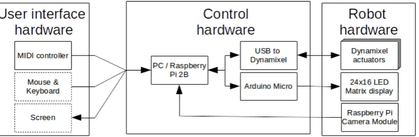
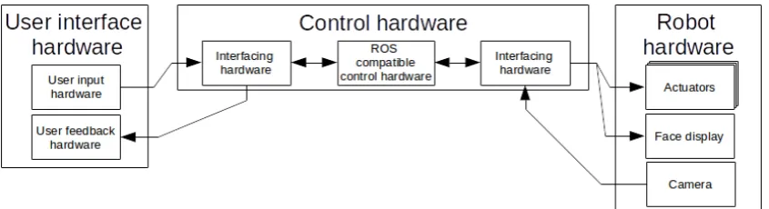
[image:12.595.74.497.216.331.2]The robot is categorized into three parts, which are: user interface hardware, control hardware and robot hardware. These parts are connected as shown in figure 2.1. The implementation of the hardware architecture is shown in figure 3.1.
Figure 2.1:The general system hardware architecture of the robot.
User interface hardware
The user interface hardware consists of hardware which enables manual user input and hard-ware which enables feedback to the user.
Control hardware
The control hardware of the robot consists of an embedded or non-embedded system. The control hardware is connected to the user interface hardware and robot hardware through in-terfacing hardware. The control hardware determines the relationship between user-input and robot-output.
Robot hardware
The robot consists of actuators, hardware to communicate emotions to the user and a camera.
2.2.2 Software architecture
In figure 2.2 the software architecture of the toolkit is shown. The implementation of the soft-ware architecture is shown in figure 3.4.
[image:12.595.73.494.614.727.2]CHAPTER 2. ANALYSIS 5
Camera driver and object tracking
To create interesting applications, having a camera on the robot and drivers for it is useful. Also earlier work from the group can be recreated and built upon, such as the functionality shown in Reilink et al. [8] and Visser et al. [9].
Input controller driver and input controller to robot control
To puppeteer the robot, it is necessary to have input hardware supporting it, and software sup-port in the toolkit for reading the hardware input.
External software bridge
The external software bridge is necessary to connect the input from dedicated human-robot interaction software, such as AsapRealizer, to the toolkit.
Animation engine
The animation engine is the core of the toolkit and combines the input from external software and manual input. The robot behavior is generated in this module.
In the work of Fong et al. Fong2003 seven "human social" characteristics are listed, which are:
• Express and/or perceive emotions;
• Exhibit distinctive personality and character;
• Use natural cues (gaze, gestures, etc.);
• Communicate using high-level dialogue;
• Learn/recognize models of other agents;
• Establish/maintain social relationships;
• Learn/develop social competencies.
The first three items are implemented in this research. This happens in the animation engine. The final four items are out of the scope of this research.
Robot actuator controller
The robot actuator controller is used to control the actuators of the robot.
Robot face controller
The robot face controller is used to control the face of the robot.
Visualizer
Only in situations where the actual exact movements of the robot are relevant, making an ad-vanced model of the robot’s dynamics is beneficial. However, in this case we wish to enable developers who do not have the actual robot in their posession (yet) to create applications and test algorithms by getting visual feedback. Therefore only the kinematics of the robot are modeled and not the dynamics. The output of the visualizer is displayed on a screen.
2.3 Background
2.3.1 Appearance
[image:14.595.129.444.183.439.2]Duffy [11] has discussed the issues pertinent to the development of a meaningful social interac-tion between robots and people through employing degrees of anthropomorphism in a robot’s physical design and behavior. As robots enter people’s social space, they inherently project their interpretation on their actions similar to the techniques people employ in rationalising, for example a pet’s behavior. In figure 2.3 the three primary categorisations for robots employ-ing anthropomorphism to some degree are shown with examples.
Figure 2.3:The three primary categorisations for robots employing anthropomorphism to some degree as described by Duffy [11].
To avoid the ’uncanny valley’ as described by Mori [12] it is a better choice to choose a hu-manoid design rather than an android design. Therefore the robot should be more towards the abstract or iconic categories, as in figure 2.3 and avoid trying to look too much like a human in terms of appearance.
2.3.2 HMI’s human-robot interaction software
The HMI group makes use of AsapRealizer, which is a behavior realizer for virtual humans. It makes use of the Behavior Markup Language, BML, as proposed by Kopp et al. [13]. BML is an international effort to unify a multimodal behavior generation framework for Embodied Conversational Agents.
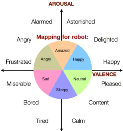
2.3.3 Valence and arousal
The term valence can be described as ’how positive’ an emotion is. Arousal can be described as ’the amount of energy’ in an emotional state. In figure 2.4 several common emotions are shown on a 2D arousal/valence plane along with the mapping of six basic emotions to this plane. The intensity of the emotion is determined by the length of the 2D arousal and valence vector, while the emotion is determined by the angle of the vector.
2.4 Requirements
CHAPTER 2. ANALYSIS 7
Figure 2.4:The mapping from arousal and valence to an emotion and intensity.
2.4.1 Robot requirements
The robot features:
• a maintainable, minimalistic, scalable and modular design by using replacable ’plug-and-play’ parts to keep the entry threshold for new developers to a minimum and to maximize the robot uptime;
• an iconic and abstract appearance rather than a human-like appearance as to avoid the ’uncanny valley’.
2.4.2 Toolbox requirements
The toolbox provides:
General
• an open source modular software design with a quickstart guide to make future develop-ment easier;
• visualization, without any dynamics, of the robot for development;
Operating modes
• a demonstration mode which showcases the robot;
• a direct-control mode to operate the robot manually by use of a physical input device;
• an external input mode, to puppeteer the robot using dedicated human-robot interac-tion software;
• an object tracking mode,
• an saccade-eye-following mode in which the robot head follows the eye movement;
Social behavior
• generation of autonomous movement such as eye blinking and breathing;
• ways to exhibit distinctive personality and character which are dynamically reconfigur-able.
9
3 Design
In this chapter the implementation of the system is treated. The technical information about the system, including the hardware and software design decisions taken, are shown. The chapter begins by giving the complete overview of the hardware design, after which the design decisions are explained. Then, same is done for the software design. For the tables in this chapter comparing different design options, a plus means the design option is better in the specified property and a minus means the opposite.
3.1 Hardware design
[image:17.595.97.515.311.448.2]In this section the design options for the hardware are explored and design decisions are ex-plained. The blocks from figure 2.1 are filled in here, in figure 3.1. It gives an overview of the hardware design of the robot. The dotted ’Mouse and Keyboard’ and ’Screen’ blocks mean that these parts are only attached during development. In appendix C the used hardware parts are listed.
Figure 3.1:The robot’s hardware design. The dotted ’Mouse and Keyboard’ and ’Screen’ blocks mean that these are only attached in the non-embedded or development mode.
3.1.1 User input hardware
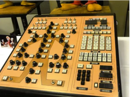
To be able to operate the robot by hand, at least one input device should be selected. Clas-sical ways to do so for puppeteering of animatronics for live performances are mostly with gamepads, radio controlled remotes (similar to thos of toy cars) or dedicated control panels, such as in figure 3.2.
In table 3.1 the options for the input hardware are listed. An IMU1is one of the choices. It can be used in the same way as a 6 DoF mouse.
Six-degrees-of-freedom control by using for example a haptic feedback device is an interesting control method. However, it is not well portable and an expensive solution. Also, it involves inverse kinematics to map the six DoF’s of the input to three DoF’s of the robot, which increases system complexity and it does not enable on/off activations by switching. The same goes for the IMU solution, only the IMU is less expensive and more portable. The mouse has too few buttons to enable quick control, or it would require a screen to select options. The keyboard lacks analog input. The gamepad lacks precision in the analog input and has fewer analog inputs.
Therefore, the MIDI control panel is chosen as the input device for the robot. It has the same advantages as the controller shown in figure 3.2: it enables precise analog input movement and
Figure 3.2:An old programming console for Disney Animatronics. Each knob and button activates the corresponding body part as indicated on the console. The knobs are used for precise analog movement and positioning while the buttons are used for digital on/off activation’s.
Midi control panel IMU 6 DoF controller Mouse Keyboard Gamepad Slidable
adjust-ments
++ ++ ++ ++ - - ++
Low cost + - - - ++ ++ ++
Simultaneous control of different joints
++ ++ + - - ++
States visable from controller ++ ++ ++ - - - -Direct coup-ling between end-effector and controller ++ ++ ++ ++ - -
-System simplicity ++ - - - - ++ ++ ++
Resolution - ++ ++ ++ - -
-Enables steady op-erator movement of robot
+ - - - +
-Table 3.1:A comparison between design options for the manual controller.
positioning, simultaneous control of several joints and buttons, for on/off activations. Also, because it is an off-the-shelf part, it is a maintainable and scalable solution. The mapping of the MIDI controller to robot controls and an image of the MIDI controller with labels on it for the controls are shown in appendix A.
3.1.2 Control hardware
[image:18.595.73.538.297.543.2]CHAPTER 3. DESIGN 11
RaMstix Raspberry Pi 2B Non embedded (e.g. PC)
Transportability ++ ++
-Short connection lines ++ ++
-Processing power - - +
Flexibility while developing - - - ++
Modularity + +
[image:19.595.103.499.79.177.2]-ROS support - + ++
Table 3.2:A comparison between various platforms to use as an embedded system.
ROS is experimentally available to both the RaMstix and Raspberry Pi board. However, more support is available for the Raspbian OS. Compared to the RaMstix board or other embedded platforms, the Raspberry Pi has the advantage of having a large user community. This means it becomes possible to work on sharable technology, with other experts. There is more tech-nical support and free-to-use work by others. It also means the platform is produced in larger quantities lowering its price. Therefore, the chosen option is to use an embedded Raspberry Pi for demonstrations and publications. For development a non embedded computer is used.
3.1.3 Face display
To display a face there are several options, which are listed in table 3.3.
Low-resolution LED screen Mini beamer LCD screen Mechanical
Low cost ++ - - +
-Electrical drivability ++ - - +
Expressibility - ++ ++ +
Mechanical simplicity ++ - ++
-Weight + - +
-Table 3.3:A comparison between design options for the face display.
For the display of a face, a low-resolution LED screen is chosen. This is because it features the mechanical simplicity of a screen (compared to using a beamer or an actual mechanical face) and it features more electrical simplicity compared to a LCD screen. An Arduino Micro is embedded in the head of the robot to control the LED screen.
3.1.4 Mechanical structure
Off-the-shelf actuators with integrated encoders and controllers can be bought, with matching mechanical connectors available. On the other hand also seperate motors, sensors and con-trollers can be used, with custom made mechanical connections in between.
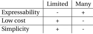
With more degrees of freedom, the robot is able to make more complex movements and reach more poses. On the other hand, the cost rises because of a higher amount of actuators which are needed. Also, the complexity of the system rises with more degrees of freedom because the amount of possible configurations increases.
Limited Many
Expressability - +
Low cost +
-Simplicity +
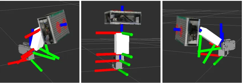
[image:19.595.89.537.366.451.2] [image:19.595.225.379.678.735.2]Because maintainability, reliability and simplicity are required, the choice for the actuators is to use only a few degrees of freedom with plug-and-play actuators. Three Dynamixel actuators are used, because of their qualities in the aforementioned properties. This means a maximum of three degrees of freedom, which is enough to demonstrate the toolkit and to perform basic human-robot interaction with.
[image:20.595.72.499.240.386.2]The configuration of the actuators is shown in figure 3.3 by four sets of axis. The images are created using the visualizer from the toolkit. The base (lower) axis represent the fixed world. The other three sets of axis represent the center of the three joints and their configuration. The actuators are placed in series. The bottom actuator controls the pitch of the robot and is limited by the software in the actuator to be between -90 and + 90 degrees. The middle and upper actuators are limited to be between 0 and 90 degrees.
Figure 3.3:Three poses of the robot to show to four sets of axis of the robot. The bottom axis represent the frame of reference. The other three represent the frames of the joints of the robot.
3.1.5 Camera
For image processing applications a camera is attached to the top of the robot’s face It is moun-ted onto the robot, so object tracking has a wider range and applications such as an outer-body-experience through the robot are possible, in later projects.
For the camera a generic USB camera and Raspberry Pi camera module are available. The dif-ference in their performance is in their form factor. It is difficult to find a small, easily mount-able USB camera. Therefore the Raspberry Pi camera module is used.
3.1.6 Electronics
The specific parts used for the robot are listed in appendix C.
3.2 Software architecture
Figure 3.4 gives an overview of the software design of the robot. The difference between this figure and figure 2.2 is that now the MIDI controller is selected as the input controller for the system.
CHAPTER 3. DESIGN 13
Figure 3.4:The robot’s implemented software architecture.
3.2.1 Robotic software platform
The work of Harris and Conrad has shown that ROS is currently one of the most popular robot-ics toolkits systems [10].
The Robot Operating System (ROS) is a set of software libraries and tools built for creating robot applications. From drivers to state-of-the-art algorithms and with several tools, ROS offers a lot of free open source content.
ROS was designed to be as distributed and modular as possible, so that users can use as much or as little of ROS as they desire. To accomplish the modularity, ROS works with the publish-subscribe pattern. It can incorporate many commonly used libraries for specific tasks instead of having to have its own custom libraries.
Ubuntu is the supported platform for ROS. It is possible to run ROS within a virtual box, al-though this commonly causes issues with hardware. Because ROS runs in Linux, it is possible to apply it on a Raspberry Pi.
In terms of visualization, ROS offers a visualizer, Rviz.
ROS is a generic package for robotics with a large user community. Because of its function-ality, large user base, it being free to use and it being open source, ROS is the used software framework in this project.
3.2.2 Camera driver and object tracking
For reading out the camera the picamera.array module2is used. Object tracking is implemen-ted by means of blob tracking. For this an image, with a resolution of 20x15 pixels, from the camera is used. This resolution is chosen because the Raspberry Pi has limited processing power and in this way a framerate of 32 Hz is realized, which is enough for a proof of concept for object tracking. A light shade of green is chosen as the tracked color, since it is not com-monly used. If the color intensity of green of a pixel is 1.3 times larger than the intensity of both red and blue, the pixel is used in calculation of the mean of the blob. These thresholds have been selected by trial-and-error. The object tracking module publishes the location and size of the blob, so the animation engine can use it.
3.2.3 MIDI driver and MIDI to robot control
For the MIDI driver the pygame.midi module3is used. The MIDI driver module publishes the MIDI data inside ROS so other modules can subscribe to it. The MIDI to robot control module uses the MIDI input to send commands to the animation engine.
3.2.4 External software bridge
The external software bridge is configured to subscribe to ROS nodes from other dedicated social software. The HMI group supplied a ROS node which publishes messages compatible with the external software bridge module, so the robot can be controlled with AsapRealizer.
3.2.5 Animation engine
The animation engine is the heart of the toolkit. The animation engine is described in section 3.3.
3.2.6 Robot actuator controller
To control the Dynamixel actuators from the Raspberry Pi, the dynamixel-motor package4is used.
3.2.7 Robot face controller
One of the ROS nodes is running on the embedded Arduino Micro. This node is subscribed to the face state output of the animation node. This implementation enables the face display of this robot to be attached to any ROS based project. For the communication between the Arduino and the Raspberry Pi the rosserial package5is used..
3.2.8 Visualizer
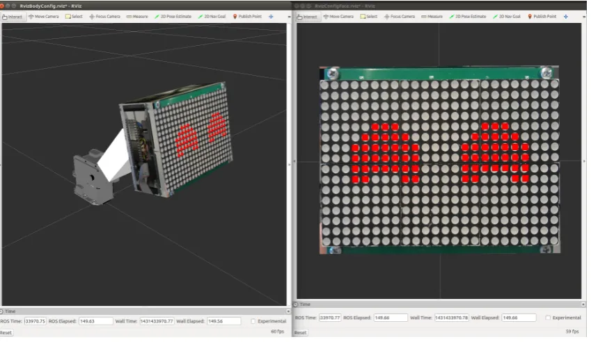
[image:22.595.75.500.414.660.2]For development purposes a visualizer of the robot necessary. ROS supplies a 3D visualization tool, which is called Rviz6. A 3D model of the robot is made and in figure 3.5 the visualization is shown.
Figure 3.5:(Left) A visualization of the robot in 3D, using Rviz. (Right) A frontal view of the visualized face using Rviz.
4http://wiki.ros.org/dynamixel_motor
CHAPTER 3. DESIGN 15
Robot dynamics model
The robot is modeled without inertia or friction, as a servo system. The model is made in the Unified Robot Description Format (URDF). The model is used to calculate the link positions using the states of the joints of the robot, using the tf package7supplied by ROS.
Robot 3D model
A 3D model of the robot is created, using models of the actuators found on the actuator produ-cer’s website and by making a 3D model in Blender using pictures of the robot.
Robot face
To visualize the face of the robot, the Arduino drivers for expressing emotions on the LED screen are ported to ROS. This way the robot face looks exactly the same in the visualization as in reality which enables better development of animations when the real robot is not avail-able.
3.3 Animation engine
[image:23.595.88.513.343.447.2]In figure 3.6 an overview of the animation engine is given. In the following subsections the low-level, mid-level and high-level control are explained, in that order.
Figure 3.6:An overview of the animation engine module’s architecture.
The robot can be in a few different modes which are:
• Normal mode;
• demo mode;
• object tracking mode;
• eye saccade following mode.
These modes can make use of mid-level and low-level control functionality. The mid-level functionality is:
• Gaze at location / assume certain pose;
• start homing;
• perform pre-programmed animations;
• breathe and blink with eyes.
3.3.1 Low-level control
The high-level control can also use the low-level control and thus directly set the state of the face and actuators. The low-level control contains a safety layer which makes sure the robot can never damage itself, even when the external social software controller sends erronous control values.
3.3.2 Mid-level control
The mid-level control functionality is explained in this subsection.
Gazing
The robot can gaze at a certain position in space. It adjusts its pose accordingly to gaze at the desired position in space by generating setpoints for a trajectory using linear interpolation and a time before the gaze has to be completed.
Homing
Homing is a special form of gazing, in which the robot returns to a pre-configured home posi-tion.
Animations
Robot animations are defined as the robot’s face displaying emotions and the joints assuming certain matching states. There are several animations available, which can be played using buttons on the MIDI keyboard. These are nodding, shaking and dancing. The speed of these basic animations is configurable.
Breathing
When the robot is idle, some movement is still present to express liveliness. The motion is influenced by two parameters, frequency and amplitude, setting the extent of the offset from the current desired position of the actuators, in a similar way as in the work by Hoffman et al. Hoffman2008.
Eye blinking
The robot blinks with its eyes to convey a liveliness. The blinking is implemented by modulat-ing a sine onto the eyes’ vertical size. The blinkmodulat-ing is not yet dynamically configurable.
3.3.3 High-level control
In this subsection the functionality of and multimodal rules for high-level control are ex-plained.
Normal mode
This is the default mode of the robot. All functionality such as user input, breathing, blinking, mode selection, changing personality-defining parameters etc. is available.
Demo mode
Using the the basic animation and gazing movements, more advanced animations are created, which are put into a one minute demo. The purpose of this demo is to demonstrate all emo-tional and expressive capabilities of the robot without having to puppeteer the robot to do so. In these animations the robot:
• Falls asleep;
CHAPTER 3. DESIGN 17
• does a happy dance;
• shakes its head and looks down sadly;
• looks around sadly;
• shakes its head while moving forward and looking angrily;
• looks around angrily;
• moves its head forward and looks amazed.
The following rules are set for the demo mode.
• Breathing is disabled because all behavior of the robot is prescripted.
• Only the stop button is available to the user, other input is negated.
• After pressing the stop button the robot transitions back to the pose desired by the MIDI input by using the mid-level gazing functionality.
Object tracking mode
In object tracking mode the robot tracks a green blob. The robot face is becoming more and more sad when the blob has not been seen for a few seconds. The robot face becomes in-creasingly happy when the blob is detected again. If the blob is not seen for a while, the robot performs homing, so it is again in its neutral state.
The following rules are set for the object tracking mode.
• Breathing is disabled to have more precision for object tracking.
• Only the stop button is available to the user, other input is negated.
• After pressing the stop button the robot transitions back to the pose desired by the MIDI input by using the mid-level gazing functionality.
Eye saccade following mode
To follow where the eyes are focussing, a smoothing filter has been used. This filter smoothes the movement of the head, which creates a small delay between the movement of the eyes and the head which makes the head movement follow the eye movement.
In this mode, only the face state can be changed and the stop button can be used. The actuators follow the location of the eyes and move until the eyes are in the middle of the face again. After pressing the stop button the robot transitions back to the pose desired by the MIDI input by using the mid-level gazing functionality.
3.3.4 External input
External software is able to control the robot through the animation engine as shown in figure 3.6. Therefore, several levels of control are exposed to, in which the external controller is free to switch between these levels of control. The toolkit determines how to handle these inputs. The exposed levels of control are:
• Low-level: Direct control of the facial expression and motor position.
• Mid-level: Gaze at a certain position, start an animation, etc.
3.3.5 Setting emotions
[image:26.595.73.498.145.357.2]Six different emotions can be displayed on the robots display being: neutral, sleepy, angry, sad, happy and amazed. The intensity of the emotion can be varied so the face has different degrees of sadness, angriness, etc. In figure 3.7 the different emotion states of the face are shown.
Figure 3.7:The six different emotions as implemented on the robot, from left to right starting at the top: neutral, sleepy, angry, sad, happy and amazed.
Emotion and intensity
Using different buttons, an emotion state of the face display can be chosen and using a slider the intensity can be set. Alternatively, the emotion state can be set using valence and arousal sliders, as explained in section 2.3.3.
3.3.6 Expressing a personality
The way the robot moves can be changed at any time. By changing those things, the conveyed personality is also changed. For example: a robot which moves quick and directly conveys a different personality than a robot which moves smoothly. The following implementations help to express a personality:
• Breathing, at a configurable pace
• Eye blinking
• The speed of the animations
• Compression on movement range
• Movement smoothing
19
4 Results
In this chapter the results of the project are discussed. The robot is shown in figure 4.1. The toolkit has been developed in parallel with the robot. A Raspberry Pi, which runs ROS, has been integrated into the robot head. This increased the portability of the robot a lot. An Ubuntu computer is used as the development system, which is also be used for visualization and test-ing. The toolkit has also been applied on a new robot, to validate if it is effective as a toolkit for human robot interaction. Also, a new user has performed a show with the system as to gen-erate user feedback. Several demonstrations have been given such as for national television, large university shows with over 400 visitors, open lab days and other events. The toolkit has been connected to the dedicated social interaction software AsapRealizer, made by the HMI group. The visualizer has been used succesfully by the HMI group.
[image:27.595.94.517.316.469.2]Because this project features foundational steps in building a toolkit for agile human-robot in-teraction, a quantitative analysis is difficult. Therefore, these results are mostly described in the form of user experiences and experiences gained from the performances and demonstrations.
Figure 4.1:The robot, which was developed in parallel with the toolkit.
4.1 Robot performance
One of the goals of this project is to create a robot, using the toolkit, with a high uptime, which is easily transportable and which appeals to the general public. The purpose of these listed performances is to validate if this goal has been met. Because the Raspberry Pi is embedded into the head, the robot is well transportable. Only a power supply and an optional manual controller are necessary to demonstrate the robot. The complete setup weighs 3.94 kg. This includes the power supply, MIDI input controller and footstand of about 2.5 kg, to keep the robot in place.
4.1.1 Television publications
In figure 4.2 a screenshot of the broadcasts of: ’TijdVoorMeldpunt!: Robots’ on Friday April 7th 2015 and ’Universiteit van Nederland’ on Wednesday December 3th 2014 are shown. The robot was used to demonstrate the impact of social robotics and how a robot can show emotions and interact with people.
4.1.2 Interactive demonstrations
Figure 4.2:A screenshot of a broadcast of: (Left) ’TijdVoorMeldpunt!: Robots’ on Friday April 7th 2015 and (Right) ’Universiteit van Nederland’ on Wednesday December 3th 2014
the robot on April 8th 2015, while it’s on manual input mode. The picture on the right shows children engaged with the robot while it is in demonstration mode, on April 27th 2015.
Figure 4.3:(Left) A visitor playing with the robot, on April 8th 2015, while the robot is on manual input mode (photo courtesy of Alexander Dziouba). (Right) Children engaged with the robot while it is in demonstration mode, on April 27th 2015.
The robot was also used by prof.dr.ir. Stefano Stramigioli in a live demonstration during a presentation in Utrecht and gave as feedback the robot worked fantastically. The demo mode of the robot enabled him to demonstrate the robot to the audience with one press of a button.
Other occassions where the robot has been used are open laboratory days and business related lab visitors. On all these occassions the robot performed satisfactory.
The general response from people on seeing the robot being demonstrated was enthusiastic. The breathing and blinking behavior realized by the toolkit gave people the feeling the robot was more of an actual being than an assorted heap of parts. General feedback of the audiences included the robot being cute. People controlling the robot with the manual input controller commented that they enjoyed how direct the mapping between the controller and the robot movement felt and that they enjoyed playing around with it.
4.1.3 Case study: Live show performance with two puppeteered robots
[image:28.595.73.499.283.479.2]CHAPTER 4. RESULTS 21
[image:29.595.92.516.129.271.2]In figure 4.4 on the left a screenshot of the video performance for the submission video for the ’Popster!’ television show, from November 2014, is shown. On the right the same performance for the University of Twente’s High Tech Fashion Show event on June 2nd 2015 is shown.
Figure 4.4:(Left) Screenshot of the video performance for the ’Popster!’ television show, from November 2014. (Right) The same performance for the University of Twente’s High Tech Fashion Show event on June 2nd 2015.
The performance features two robots. One of the robots assumes an excited upbeat character and the other robot assumes a grumpy character.
The performance begins with music starting with one robot sleeping and the other robot no-ticing the music. The happy robot starts dancing to it, while the grumpy robot wakes up, an-noyed. An interaction between the two takes place where the happy robot teases the grumpy one, by moving towards it and changing the face state to happy, while the grumpy one turns its face state to angry.
At the cue in the music, the happy robot becomes to excited and crashes. Now, the crashed robot has the sleeping face emotion state while the grumpy robot first shows his amazed face and then the sad face. After a while the music starts again and because the grumpy robot en-courages the other one to come back to life and dance along, the crashed (previously happy) robot comes back to life and they dance together.
The people of the broadcasting station, Talpa, gave a lot of positive feedback about the formance. Therefore, a performance was recorded in their studios. After comparing our per-formance with those of other puppeteering acts, they considered the perper-formance too static in comparison, because the robots were not mobile. They also suggested puttings wigs on the robot, to further exhibit distinctive personality and character.
4.1.4 Case study: Performing the live show with a new user
The same live theatre performance as the one made for the ’Popster!’ television show was per-formed with a new puppeteer, Salua Hamaza. In figure 4.4, on the right, a picture taken at the performance of the show is shown. It took Salua about half an hour to get acquainted with all the basic controls of the robot. It took her another half hour to get comfortable with the performance and to be able to control the robot exactly as she wanted to.
She thought performing with the robot it was really cool, she really enjoyed it. In her consider-ation, you can have fun with the robot anytime without having done a lot of training.
a certain degree of control, so for example kids can play with the robot through a limited set of controls and more advanced users can have access to all functionality.
She thinks the configuration and amount of joints is good because the robot is well controllable, yet still has enough expressability. Because the robot configuration is simple you can actually master moving the robot in exactly the way you want. By adding more joints controlling it would be harder.
4.1.5 Personal experience
From personal experience, the breathing proved itself convenient in demonstrations, because generating that kind of behavior by hand is difficult and strenuous. It enables the puppeteer to focus on other aspects of performing with the robot. The same goes for the built-in animations and demo mode, they add convenience to the puppeteering and improve the demonstrational performance of the robot.
From personal experience it was also noted that a personal connection with the robot arose. When the robot hardware had to be modified with a drill, for example, it felt weird. The robot started feeling more like a living creature than as a robot. Another interesting result of pup-peteering and developing the robot is that if the displayed emotion on the robot is for example sad, the puppeteer is also assuming a sad face. This could be the psychological principle of mirroring at work, which commonly occurs in human interacction.
4.1.6 Head movement speeds
The actuators of the robot are configured using internal controllers. The way they are con-figured, the movements speeds of the joints are as follows:
• Pitch joint: 360◦/s
• Middle joint: 250◦/s
• Top joint: 320◦/s
4.2 Toolkit performance
One of the goals of this project is to create a toolkit for agile human-robot interaction with a focus on modularity and expandability which can be connected to an external input such as social behavior realizer. To validate if the toolkit can indeed be applied to other robots and to connect it to AsapRealizer, some case studies has been done.
4.2.1 Case study: Connecting the robot to AsapRealizer
In collaboration with the HMI group, the robot is connected to the social human-robot interac-tion software platform AsapRealizer. Their feedback after using the toolkit to write their part of the software was: "The toolkit is CLEARLY coded and just doing what it should do!". A proof of concept is performed in which AsapRealizer starts different animations on the robot over the internet from a remote computer, which demonstrates the robot as an embodiment of a virtual agent. In figure 4.5 a screenshot of the software used to control the robot remotely using BML is shown. The software produces spoken text and contains the movements of the robot.
4.2.2 Case study: Applying the toolkit on a new robot
CHAPTER 4. RESULTS 23
Figure 4.5:Dedicated social software connected to the toolkit. Shown here, the BML player which pro-duces spoken text and contains the movements of the robot.
4.2.3 Visualizer
The visualization module was used extensively by the HMI group for making a connection between AsapRealizer and the toolkit. The feedback from the HMI staff was that the visual-izer enabled them to develop their part of the software and instantly test it out, without having the robot in their possession.
Since the simulator uses no inertia in its model, the error between the view in the visualizer and reality is the difference between the setpoint and the actual location determined by the speeds in subsection 4.1.6.
4.2.4 Sample time
When running simultaneously with the other parts of the toolkit, on a Raspberry Pi, the object tracking outputs the position of the blob at 32 Hz at a resolution of 20x15 pixels. By using ROS’
[image:31.595.248.356.562.744.2]25
5 Conclusion
In this chapter conclusions are drawn. After that, some recommendations are made for future work.
5.1 Conclusions
The first goal of this project was to create a toolkit for agile human-robot interaction with a focus on modularity and expandability which can be connected to an external inputs such as a social behavior realizer.
The foundation for a human-robot interaction toolkit has been laid. The modularity and ex-pandability of the toolkit are realized by dividing the toolkit up into modules, by using open source, well documented software building blocks and by implementing the toolkit in ROS. The toolkit is controllable by use of a MIDI controller, which proved itself an excellent control method.
The dedicated social human robot interaction software from the HMI group, AsapRealizer, has been connected to the toolkit in a proof-of-concept manner. Their group was satisfied with the performance of the toolkit and its visualizer. The visualizer proved itself useful in the develop-ment process of the bridge between AsapRealizer and the toolkit. The toolkit exposes several levels of control to external software and combines these different levels of control input to enable fluent robot behavior.
Applying the toolkit to a new robot, with five actuators rather than three, was succesful. It took a few hours to apply it. This means there is room for improvement, by for example focussing more on the ease of expansion towards other robots.
The second goal of the project is to create a robot using the toolkit with a high uptime, which is easily transportable and which appeals to the general public.
The robot hardware proved itself robust during the development and demonstrations and has an iconic and abstract appearance. The uncanny effect was completely absent in interviewed observers. Mostly plug-and-play parts are used, making the robot easily maintainable.
The demonstration mode of the toolkit in combination with the robot proved itself useful in several demonstrations, for visitors of the laboratory as well as on television and shows. The toolkit, in combination with the robot, has the ability to perform eye saccades, express emo-tions, generate autonomous movement and offers ways to exhibit distinctive personality and character.
Seeing the robot in action in context by demonstrations and receiving feedback allowed to re-flect better on usage scenarios for future improvement on the toolkit.
The first research question is how to create a platform for social robotics using a minimalistic hardware configuration. The approach taken in this project is to use off-the-shelf hardware and software. In this case, that means using ROS with packages supplied by the community and using off-the-shelf actuators rather than custom solutions. By limiting the degrees of freedom and choosing the auxilary hardware, such as the LED face display and MIDI controller wisely, a platform for social robotics, based on minimal hardware, is created.
Also, to enable agile human-robot interaction, multimodality is important, which proved to be more difficult than expected. Switching smoothly between input modes, animations, gazes and functionality is a big challenge and even considered a field on its own.
The third research question is what building blocks are necessary for the fundamentals of human-robot interaction. Basically, as for every robot, user input or sensors are necessary, which need to be processed in some way, after which the robot can output something back to the user. The degree to which these three components are implemented determines how sophisticated the social robot is.
The fourth research question is how to implement multimodal input for a social robot’s beha-vior. In this project this field of research was only touched upon. It’s important to consider every possible input mode and switching between this mode and all other modes. Also, the behavioral rules for every mode must be determined.
The fifth research question is how to use minimal hardware to convey a personality. In this pro-ject some form of natural movement and eye blinking have been implemented. Although the used hardware in this project is simple, the breathing and eye blinking really feel human-like. By showing human like characteristics with minimal hardware it’s possible to convey a person-ality. Personality traits are embedded in all behavior of the robot. By paying attention to detail when creating animations, a lot of subcommunicative information about the robot’s character is added. This can also be realized by parameterizing all movement of the robot, as was done in this project by, among other things, changing the smoothing of the robot movement, or the speed of the breathing and animations.
The final research question is to what extent social behavior should be integrated into a robotic hardware platform. If possible, it is useful to have a wide range of social behavior embedded into the robot. The developer should be aware that he exposes enough levels of control to the outside world, so the user can select which level of input he wants to use. Some users of the platform want to control the actuators of the robot manually, while other users just want to play animations, or control gazes.
5.2 Recommendations and future work
The listed items were not completed during this project, because they were not the main pri-ority or not in the requirements of this project. However, they make good additions to the developed robot or toolkit and should therefore be considered for future projects.
5.2.1 Software recommendations
• Featuring more forms of control of multiple DOFs without a direct anatomical mapping.
• Applying a layered acting system to achieve high quality robot animations and advanced puppeteering, as in the work of Dontcheva et al. [14].
• Implementing a graphical timeline editor for animations.
5.2.2 Hardware recommendations
• Using a 6D mouse, IMU, WiiMote or haptic feedback device as an additional controller.
• Creating an audio module which generates sounds depending on emotion.
• Adding a voice synthesis unit to the robot.
• Making a casing to transport the robot in.
CHAPTER 5. CONCLUSION 27
29
A User quickstart
In figure A.1 the used MIDI controller is shown. To control the robot, plug in the power supply and put all joint control sliders (1-3) to their middle neutral position. Also put the pitch knob to its neutral position (in the middle of its minimum and maximum value). Otherwise the robot will make a large movement when touching the controls for the first time, since there will be a large difference between the MIDI controller desired position and the actual position. Wait for one minute and the robot should be up and running.
[image:37.595.89.515.235.344.2]To display a demo, press the DEMO button. For other behavior, please read the notes below.
Figure A.1:The used MIDI controller to control the robot.
Next to the knobs, buttons and sliders are small labels which indicate the functionality the knobs, buttons and sliders represent. Below is an overview of the mapping of the MIDI con-troller.
The knobs are used for controlling (from left to right):
• (1) The angle of the lower pitch joint of the robot.
• (2) The frequency of the animations and breathing.
• (3) The amount of smoothness applied to the robot movements.
• (4) The amount of compression applied to the movement of the robot.
• (5-7) Not mapped.
• (8) The horizontal position of the eyes.
The buttons are used for (from up to down and left to right):
• (1-6) Not mapped.
• (7) Starting the nodding animation.
• (8) Starting the head shaking animation.
• (9) Starting the dancing animation.
• (10-12) Stopping an animation or returning to the normal mode.
• (13) Switch to the built in demo mode.
• (14) Switch to object tracking mode.
• (16-17) Not mapped.
• (18) Start a funny ’crashing’ animation for the robot eyes.
• (19) Set the eyes to the neutral emotional state.
• (20) Set the eyes to the sleepy emotional state.
• (21) Set the eyes to the sad emotional state.
• (22) Set the eyes to the happy emotional state.
• (23) Set the eyes to the amazed emotional state.
• (24) Set the eyes to the angry emotional state.
The sliders are used for controlling (from left to right):
• (1) The angle of the middle joint of the robot.
• (2) The angle of the upper ’head nodding’ joint of the robot.
• (3) The angle of the above two joints together in opposite directions, to make a zooming movement.
• (4) Not mapped.
• (5) The arousal of the emotion of the robot.
• (6) The valence of the emotion of the robot.
• (7) The intensity of an emotion of the robot.
31
B Development quickstart
B.1 Installation on Raspberry Pi
It’s recommended to use the image or SD card provided, since it has the complete toolkit already installed. It also includes an installation of OpenCV. Using the image will save a lot of time, since installation times of ROS and OpenCV combined are over 20 hours.
B.1.1 Manual installation (NOT RECOMMENDED!
Install Debian Wheezy on your Raspberry Pi and follow the instructions below. Select Debian Wheezy as your platform.http://wiki.ros.org/ROS/Installation
B.1.2 Additional packages
Some packages need to be manually installed for the toolkit to work. These are the following:
dynamixel_motor sensor_msgs nav_msgs tf dynamic_reconfigure
For the MIDI controller the python-pygame package is needed.
The installation of the needed additional packages is described on: http://wiki.ros. org/indigo/Installation/Debian
At the moment of writing, the procedure would be:
$ cd ~/ros_catkin_ws
$ rosinstall_generator dynamixel_motor sensor_msgs nav_msgs tf dynamic_reconfigure --rosdistro indigo --deps --wet-only
--exclude roslisp --tar > indigo-custom_ros.rosinstall
$ wstool merge -t src indigo-custom_ros.rosinstall $ wstool update -t src
$ rosdep install --from-paths src --ignore-src --rosdistro indigo -y -r --os=debian:wheezy
$ sudo ./src/catkin/bin/catkin_make_isolated --install -DCMAKE_BUILD_TYPE=Release --install-space /opt/ros/indigo
sudo apt-get install python-pygame
B.2 Installation on an Ubuntu computer
B.2.1 ROS
To install ROS on a PC, follow the instructions below: http://wiki.ros.org/ROS/ Installation
Make sure to choose the full installation with everything (such as Rviz) included.
B.2.2 Additional packages
Then, two additional packages are needed for the dynamixel motors and MIDI keyboard:
B.3 Tips
B.3.1 RS485 trouble?
To get the RS485 connection up and running in most cases one should run the following line to stop the modem manager from messing with the RS485 connection.
sudo apt-get remove modemmanager
B.3.2 Python ROS node not visible
If a Python ROS node you created is not visible when you try rosrun and you press ’tab’ twice for autocompletion, first check if you sourced your workspace:
source devel/setup.bash
If that doesn’t solve the problem be sure to change the change the access permissions of the .py file to make sure the system knows it’s an executable. Do this using:
chmod 755 mynode.py
B.3.3 Making things easier .bashrc file
The content of your .bashrc file is ran every time the terminal is opened up. If ROS is used a lot on the system it might save some time to add the following to your .bashrc file:
source /opt/ros/indigo/setup.bash cd ~/.../YOURROSWORKSPACE/
source devel/setup.bash
Remote desktop to the Raspberry Pi
It might be easier to connect through a remote desktop connection rather than connecting a mouse, keyboard and monitor.
B.3.4 Running the toolkit
33
C Electronic parts list
Below all of the used electronics are listed. This table can be used when parts of the robot need to be replaced, or to build another robot.
Part: Description:
Raspberry Pi 2 Model B The embedded control hardware. 8 GB Micro SD card For usage with the Raspberry Pi.
Arduino Micro Controls the 24x16 LED matrix as a ROS node.
12V 5A power supply Power supply for the actuators and for the 12V to 5V chip. 12V to 5V Switching power converter Power supply for the Arduino, LED matrix and Raspberry Pi. USB to RS485 converter For controlling the actuators with the Raspberry Pi.
35
Bibliography
[1] Herwin Van Welbergen, Ramin Yaghoubzadeh, and Stefan Kopp. AsapRealizer 2 . 0 : The Next Steps in Fluent Behavior Realization for ECAs. In Timothy Bickmore, Stacy Marsella, and Candace Sidner, editors,Intelligent Virtual Agents, volume 8637 ofLecture Notes in Computer Science, pages 449–462. Springer International Publishing, 2014.
[2] John Bohannon. Meet your new co-worker: At the vanguard of human-robot interactions is Baxter, a bot quick on the uptake that even knows how to cheat.Science, 346(6206):180– 181, 2014.
[3] Michael Kipp, Alexis Heloir, M. Schröder, and Patrick Gebhard. Realizing Multimodal Be-havior.Intelligent Virtual Agents, pages 57–63, 2010.
[4] T. Watanabe, A.H. Mader, and E. Dertien. Exploring anti-social behaviour as a method to understand aspects of social robot behaviour.International Conference on Human Robot Interaction (HRI), 2013.
[5] Terrence Fong, Illah Nourbakhsh, and Kerstin Dautenhahn. A survey of socially interactive robots.Robotics and Autonomous Systems, 42(3-4):143–166, March 2003.
[6] Guy Hoffman, Rony Kubat, and Cynthia Breazeal. A hybrid control system for puppeteer-ing a live robotic stage actor. InRO-MAN 2008 - The 17th IEEE International Symposium on Robot and Human Interactive Communication, pages 354–359. IEEE, August 2008.
[7] Cesar Vandevelde, Jelle Saldien, Maria-cristina Ciocci, and Bram Vanderborght. Ono, a DIY Open Source Platform for Social Robotics. 2014.
[8] R. Reilink, L. C. Visser, J. Bennik, R. Carloni, D. M. Brouwer, and S. Stramigioli. The Twente humanoid head. 2009 IEEE International Conference on Robotics and Automation, pages 2009–2010, 2009.
[9] L.C. Visser, R. Carloni, and S. Stramigioli. Vision based motion control for a humanoid head. 2009 IEEE/RSJ International Conference on Intelligent Robots and Systems, pages 5469–5474, 2009.
[10] Adam Harris and James M. Conrad. Survey of popular robotics simulators, frameworks, and toolkits.Conference Proceedings - IEEE SOUTHEASTCON, pages 243–249, 2011. [11] Brian R. Duffy. Anthropomorphism and the social robot. Robotics and Autonomous
Sys-tems, 42(3-4):177–190, March 2003.
[12] M. Mori. The uncanny valley, 1970.
[13] Stefan Kopp, Brigitte Krenn, Stacy Marsella, Andrew N. Marshall, Catherine Pelachaud, Hannes Pirker, Kristinn R. Thórisson, and Hannes Vilhjálmsson. Towards a common framework for multimodal generation: The behavior markup language. InLecture Notes in Computer Science (including subseries Lecture Notes in Artificial Intelligence and Lecture Notes in Bioinformatics), volume 4133 LNAI, pages 205–217, 2006.
[14] Mira Dontcheva, Gary Yngve, and Zoran Popovi´c. Layered acting for character animation.
![Figure 2.3: The three primary categorisations for robots employing anthropomorphism to some degreeas described by Duffy [11].](https://thumb-us.123doks.com/thumbv2/123dok_us/9836210.484908/14.595.129.444.183.439/figure-primary-categorisations-robots-employing-anthropomorphism-degreeas-described.webp)