Munich Personal RePEc Archive
Calculation method for the energy loss in
the pneumatic mining networks
Petrilean, Dan Codrut and Irimie, Sabin Ioan and
Munteanu, Rares
University of Petrosani, Romania, Politehnica University of
Timisoara, Romania, University of Petrosani, Romania
January 2013
Online at
https://mpra.ub.uni-muenchen.de/50249/
Calculation Method for the Energy Loss in the Pneumatic Mining
Networks
DAN CODRUT PETRILEAN
Department of Mechanical Engineering, Industrial and Transport, University of Petrosani, University
street, no.20, 332006, Petrosani, ROMANIA, [email protected]
SABIN IOAN IRIMIE
Department of Management, University Politehnica Timisoara, Square Victoriei, no. 2, Timisoara,
300006 ROMANIA, [email protected]
RARES MUNTEANU
Department of Management, Ingineria Mediului
ș
i Geologie, University of Petrosani, University
street, no.20, 332006, Petrosani, ROMANIA, [email protected]
Abstract: We popose a calculation method by which we can estimate the value of the loss of pressure along the pipeline, the loss of pressure per length meter of network and the cost of the pneumatic energy loss in the case of the horizontal and vertical pneumatic network. The proposed method is validated by a study case.
Key-Words: pneumatic network, loss of pressure, drop of temperature, cost of pneumatic energy loss, energy loss
List of used symbols:
d- diameter of the pneumatic pipeline (m);
V - volume flow of compressed air (m3/s); m - mass flow (kg/min);
P – area of the mining work (m); S – cross section (m2);
ko– coefficient of energy loss for the horizontal network;
kv– coefficient of energy loss for the vertical network;
ta– temperature of the compressed air;
tin– temperature of the air inside the pipe;
Ce– cost of the pneumatic energy;
p1– incoming pressure in the pneumatic network section (N/m 2
);
T1– temperature of the incoming compressed air entering the pneumatic network section (K);
p2– pressure of the compressed air exiting the pneumatic network section (N/m 2
); T2– temperature of the compressed air exiting the pneumatic network section (K)
ad
- adiabatic efficiency of the flow; p
- loss of pressure (bar);
- coefficient of friction; Re – invariant Reynolds;l
C – cost of energy loss per meter and hour (lei/(m·h)) o
l
C – cost of energy loss per meter and hour in the case of the horizontal network (lei/(m·h)) v
l
C
– cost of energy loss per meter and hour in the case of the vertical network (lei/(m·h)) k – adiabatic exponent;R – natural constant for the air (J/(kg·K))
Tcond– external temperature of the compressed air pipeline for a certain length of the pipe
λ – coefficient of thermal conduction (W/(m·K));
αe– coefficient of thermal convection at the outer side of the pipe (W/(m 2
cp – isobar massic specific heat of the air (J/(kg·K)) x – absolute humidity;
x1– absolute humidity at the surface of the mine;
r – water vaporization latent heat (J/(kg⋅K))
l
x
- change of the absolute humidity per length meter.p
- average pressure per meter of air column (mmHg/m) H – depth of the vertical work (m);B – barometric pressure on the surface (mmHg);
1 Introduction
The energy reuired for operating the pneumatic euipment and machines from the underground mining works is provided by the pneumatic energy generator through a pipeline network.
In order to argue the importance of the study, we remind that the temperature, the pressure, the flow of the compressed air are basic parameters of the pneumatic networks and determining them is useful as well as necessary for the rational operation of the pneumatic energy consumers.
The pipeline network can be extremely complicated in its extension hrozontally as well as vertically. The diameters of the pipes vary depending on the distance and the type of the equipment they serve. The network has losses of energy (power) on the way from the compressor until the consumer.
The problem of determining the loss of pressure, flow and enery (power) within the networks of compressed air was presented in [1], [2], [3] si [4]. The results obtained show a significant percentage of the massic debit losses when connecting the consumers (27.98%), major loss on the distribution network (14,99%) and smaller losses on the main network (4,89%)[1]. The most significant energy losses on the network are recorded due to flow loss through non-tightness spots – at a flow loss of 50.702% (36.661% network losses and 14.041% consumer losses), corresponds an energy loss of 48.938% (36.958% network losses 12.34% consumer losses); the influence of pressure losses is insignificant as a percentage in the energetic balance of the system compressor – network – consumer[5].
The energetic changes in the network are due to the variation of the kinetic, potential and internal energy and on the other hand to the changes of energy. We use the classical method to determin the parameters of the network, through iterative computing, using average values for the section of pipe, knowing the parameters of the initial stage at exiting the compressor and the final one at the last pneumatic consumer [3]. This method requires pressure and temperature measurements in the initial and final points of the pneumatic network, being
significantly different as compared with the proposed method.
This study is realised in time for only one space coordinate. The elements of novelty in this paper consist of:
1. the loss of pressure in the compressed air pipelines can be computed depending on the initial parameters without mediations on the considered section, as it usually is done. This is the novelty of the proposed method;
2. distinct computing methods for the loss of pressure and temperature for the case of horizontal and vertical pneumatic network. In view of determining the fall of temperature we get a solution as integral (relation 16).
The validation of the results obtained is realised through a case study.
2 Model overview
2.1 The case of the horizontal pneumatic
network
The fundamental parameters of a pneumatic network are its diameter and its flow. Depending on these parameters, the loss of energy in relation to the pipe length and to the time are calculated by the following relation[7]:
h m
lei d
V k C
, l
l 5
852 2
(1)
where:
0148 22 2
852 1 2 852 2
1 1 6
5 13 098
0 10
0187
0 .
ad e . .
l . T .
C
p T T
p .
k
(2) For a given (known) diameter and flow, the cost of the lost pneumatic energy depends on the parameters of the environmental air as well as on the specific condition of the installation.
kk
w
T
R
d
l
k
k
p
p
1 2 1 1 12
1
1
1
(3)as the friction coefficient on (3) depends on the pipe rugosity and on the Re and is calculated by the relation: 148 0 148 0 0624
0. d. Re.
(4)
Certain parameters p and T of the network, must be found for any lengths of pipes.
Due to the length of the distribution network, an inherent loss of pressure (energy) occurs. Just after the compressor, the cooling is more intense due to the high difference of temperature between the compressed air and the environment and is lower for the rest of the network. The polytropic index that characterizes the transformation is variable. As we measure the initial and the final parameters, we can determine an average polytrope exponent.
The measurements „in situ”, that were carried
out in a great number of stations for helicoidal compressor in Jiu Valley [1], [2], [3] led to the conclusion that the process is polytropic and almost adiabatic, so that n ≈ k. The pneumatic network inside the mines is heating the surrounding air, as it has a higher temperature.
Identically, the thermal resistance of the wall is omitted, because the wall is thin and the coefficient of conduction for the metal is high. In the sistems for air ventilation in mines, the speed of the air is low compared with other branches of the industry, both in shafts and in the galleries and ranges between 0,2 ÷ 11,0 m/s [3],[4]. The coefficient of
conduction of the rock λ was experimentally
determined through laboratory trials for hard
sandstone, predominant in Jiu Valley’s coal basin ,
) K m /( W , ,
12 20 [6].
Generally, the technical literature considers for the usual mine works the coefficient of convection
m K
/ W 2 25 12 [6].
The value of the coefficient of convection results from the research of M.A. Miheev and W.H. McAdams as criterion[6]:
Nu
0
.
0195
Re
0.8 (5) out of which:S
P
m
.
. . e 2 0 8 03
2
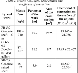
(6) [image:4.595.307.582.75.332.2]For three types of standard mining works we have measured and determined the values of the massic flow, the perimeter, the cross section and the coefficient of convection (relation (6)). The values we got are in table 1.
Table 1. Massic flow, area, cross section and coefficient of convection
Type of work Massic flow [kg/s] Perimeter of the work [m] Area of the cross section
[m2]
Coefficient of convection on the surface of the objects
[
W
/(
m
2
K
)
] PB-5,0Concrete shaft 5 m
181 –
340 15.7 19.25
13.146 ÷ 21.766 GDZ-9,7 Double-builded gallery
87 –
167 11.6 9.7 13.93 ÷ 23.467
SB-2,8 Concrete raised shaft
25 –
47 5.9 2.8
15.549 ÷ 25.764
The temperature along the pipeline results
from the equality between the internal and
external energies:
t
t
dl
d
dt
c
V
dE
p
e
e i
a(7)
The drop of temperature for the pipe with
constant diameter (hermetically closed pipes,
very well welded or flanged) is determined by
the expression:
p a i e ec
m
t
t
d
dl
dt
m K(8)
But the network of a mine is extending
vertically too, in the extraction shafts or
inclines.
2.2. The case of the vertical pneumatic
network
In reality, in the underground works, the air
enters the network from the surface, gets humid
on its way as compared with the atmospheric
air, evolving almost to a state of saturation.
The evaporation occurs by transfer of heat
with the environment according to the relation:
dv p dT c dx
r v
(9)
We admit that the absolute humidity
x
and
the pressure
p
change in a linear manner:
y
x
x
x
1
l
(10)
y
p
p
p
1
(11)
Further we find:
y
p
p
dy
p
dT
R
c
dy
R
x
x
l p
1(12)
notations:
DR x x l
;
Z
R
c
p
;
p p1.
or
Z
D
y
f
T
dy
dT
(13)
in which:
y
Z
1
y
f
.
The general integral of the equation is:
C
exp
Z
D
exp
T
fydy fydy(14)
Taking into account that:
ln
Z
y
Z
1
y
Z
dy
dy
y
f
(15)
exp dy CZ D exp
T ZlnZ y
1 y ln Z 1
(16)
At Z = 0, T = T
1, we determine the constant
C and because Z = H (depth of the vertical
work) we get:
Z Z Z Z Z H Z D H Z D T Z H Z T 1 1 1 1 1 1
(17)
in which
Z
2
Z
.
In the ratio
R
c
Z
p, the average specific heat in
the underground can be calculated by the
relation:
K
kg
J
c
x
c
x
c
p pa pv
1
1017
for the domain p = 1 bar and temperature
between 0 ÷ 50°C.
And for the natural constant R, we can take the
value of the dry air (without a significant
influence on the results).
The average pressure per meter of air
column is calculated by the relation:
m mmHg T H . B T T . p 2 2 1 0175 0 1 760 273 273 0475 0
(18)
3 Validation of the method. Study
case
In view of the validation of the proposed
method, there are required status parameters
within a helicoidal compressor station together
with the pneumatic network at which we study
the relevant energetic parameters.
Thus, based on the parameters of status
measured in a helicoidal compressor station
(Atlas Copco GA 250) in the Jiu Valley, we
determined the drop of temperature along the
work, the drop of pressure, the coefficient of
energy loss and the cost of the lost pneumatic
energy for the situation of the horizontal and
vertical network.
The measured values in the helicoidal compressor station are[2]:
- the temperature of the aspiration air 14°C; - the temperature of the air exiting the compressor
88°C;
- the temperature of the entering the cooler 88°C; - the temperature of the air exiting the cooler
40°C;
- the temperature of the air entering the pneumatic network T 39,87 0C
- the pressure of the aspiration air 0.927 bar - the pressure of the compressed air when exiting
5 bar;
- the difference of pressure in the diaphragm 123 mmHg;
- the temperature of the dry air 14°C; - the temperature of the humid air 11°C; - the relative humidity φ ~ 70%;
- the volumic flow 0.7 m3/s.
3.1.
The case of the horizontal network
parameters of the air at the inlet in the horizontal section are 287 K si 0.927 bar[2].
The cost of the pneumatic energy, based on the informations from the C.N.H. S.A. (National Hardcoal Company) is Ce = 0.5.
Using the relation (3) appropriately modified, the loss of pressure on the analized length can be written as: bar . d V T R d l k k p p k k 99 4 2 1 15 1 1 1 1 4 2 2 2 1 1
where 0,0234 for the roughness of 0,2 mm was found in [3].
On the horizontal length the difference of pressure becomes p54,990,01 bar
As applied to GDZ-97(see table 1), the relevant measured are: m 120kg/s; P11.6m şi
2
7 9. m
S . Using (6), we get
K m W . e
17824 2 .
The drop of temperature for the case of the horizontal network becomes, according to (10):
m K . m K . dl dT 100 13 0 0013 0
In this situation, according to relation (2), considering the drop of temperature/100m and the loss of pressure on the horizontal network
6
10 0422 0 .
klo .
The cost of the lost energy for the case of the horizontal network, taking into account the drop of temperature/100 m and the loss of pressure is determined by (1):
h km Eur . h km lei . h m lei ,
Clo
000152 152 034
3.2.
The case of the vertical network
Generally, the air temperature increases underground as compared with the one at the surface and can be expressed by the relation (17), in which: Z cp /R3.5; 2 875
. Z
Z
.
The status parameters of the air entering the vertical transom are 287 K si 0.927 bar.
The gradient of temperatur was determined by multiple measurements, the average value was 1 degree for 100 m of depth. Using the relation (18) for the depth of 100 m, the average pressure on the air column becomes p0,0847mmHg/m.The
values ρ and D necessary to calculate the absolute
temperature are
526
8382
,
; 0871 0 287 01 0 2500 . , R x rD l
.
It has been taken
x
l
0
,
01
from [3].As a result, as we know the values of the parameters in the relation (17), the absolute temperature at the other end of the transom becomes
K ,474
288 . The value of the temperature entering the network transom was 287 K(140C). We notice, taking into account the value obtained at the other end of the transom, that the temperature at 100 m depth increases by almost 1,5°C, so it will be 15,5
0
C.
As a result, the drop of temperature for the case of the vertical network becomes according to the relation (8): m K . m K . dl dT 100 123 0 00123 0
The value for the the coefficient of the energy loss for the vertical network is klv 0,0444106.
The cost of the lost energy on the vertical network, taking into account the relation (1) is:
h km Eur , h km lei . h m lei ,
Clv
00016 16 036 .
4 Conclusion
The paper can be seen as a method of providing data for the validation of other analytical analyses and/or numerical methods.
The method may prove its efficiency in the design or economic calculus for works opening/preparation the mine where the problem of establishing the air flow as well as the value of the temperature arises.
Based on the results obtained in the paper we can draw the following conclusions:
- the suggested method regarding the calculation of the losses of pressure is suitable for complex pneumatic networks without the need to canonize the network, procedure that cannot be used for circular or very complex networks;
- the loss of pressure in the compressed air pipes can be calculated depending on the initial parameters without using mediations on the analised transom, as it is done by classical means;
Acknowledgment
“This work was partially supported by the strategic
grant POSDRU 107/1.5/S/77265 (2010) of the Ministry of Labor, Family and Social Protection, Romania, co-financed by the European Social Fund
–Investing in people.”
References:
[1]. *** Elaboration of energetic audit for a given perimeter at Lonea Mine translate from romanian (Elaborare audit energetic pentru un contur definit la E.M. Lonea). Scientific research contract no. 10/20.07.2012. Contracting parties: Lonea Mine
(Exploatarea Minieră Lonea)- beneficiary, University of Petrosani (Universitatea din
Petroşani)- provider.
[2]. *** Comparative analysis of the energy performances of the helicoid compressors at the National Hardcoal Company Petrosani translate from romanian (Analiza comparativa a
performanţelor energetice a compresoarelor
elicoidale din cadrul CNH Petroşani), Scientific research contract no. 121, ASL/2006-2007. Contracting parties: National Hardcoal Company
Petrosani (CNH Petroşani)- beneficiary, University
of Petrosani (Universitatea din Petroşani)- provider. [3]. Irimie, I., I., Matei, I., Gas dynamics of the pneumatic networks translate from romanian
(Gazodinamica retelelor pneumatice), Technical Publishing House, Bucharest, 1994.
[4]. Dosa I., Energetics of Pneumatic Equipment
translate from romanian (Energetica instalatiilor pneumatice) Editura Tehno-Art, Petrosani 2003, ISBN 973-86469-7-9.
[5]. Petrilean D. C., Irimie I. S. Solutions to increase the energetic efficiency of pneumatic mining distribution networks, 9th International Conference on Energy, Environment, Ecosystems and Sustainable Development (EEESD '13), Lemesos, Cyprus, March 21-23, 2013
[6]. Petrilean, I., - Study of the potential thermodynamics of the mine air and their use for the calculus of aeration translate from romanian
(Studiul potenţialelor termodinamice ale aerului de mină şi utilizarea lor în calculul aerajului), PhD
Thesis, Institutul de Construcţii Bucureşti, 1988;
[7]. Czibula, R., - Considerations regarding the choice of the optimum diameter of a compressed air pipe for a given flow translate from romanian
(Consideraţii privind alegerea diametrului optim al
unei conducte de aer comprimat pentru un debit dat), Mine Petrol Gaze, Bucureşti, 1/1980.
[8]. Petrilean D. C., Determination of the energetic efficiency on a network transom at Petrila Mine
translate from romanian (Determinarea
randamentului exergetic pe un tronson de reţea de
la E.M. Petrila), Conference on thermodynamics