Study of a Kit of GSM Radio Operator Site for
Event-Driven Movable Coverage: Application to the
Deployment of a Site of the Orange Operator
in Ivory Coast
Sié Ouattara1, Georges Laussane Loum1, Koné Adama1, Alain Clément2
1
Laboratoire d’Instrumentation, d’Image et de Spectroscopie (L2IS), Institut National Polytechnique Félix Houphouët-Boigny (INPHB), Yamoussoukro, Côte d’Ivoire
2
Laboratoire d’Ingénierie des Systèmes Automatisés (LISA), Institut Universitaire de Technologie, Angers Cedex, France
E-mail: sie_ouat@yahoo.fr
Received August 29, 2011; revised September 26, 2011; accepted October 9, 2011
Abstract
The mobile communication is nowadays one of the basic needs of humanity. It is essential to the flourish- ing of human beings. Considering this reality, the need to use its mobile phone is become more important and diversified. The subscribers of the various mobile telephone operators are increasingly demanding. This situation poses the problems of the cover mobile network to the operators and leads them to opt for several solutions and investments. The mobile operators in order to satisfy their customers use a policy of pushing the limits of network coverage in time and space for festive moments in targeted zones. Thus, we have con- ducted a study on the topic: study of a kit of GSM radio site for event-driven movable coverage. This work is applied to GSM (Global system mobile) network of the operator Orange-Ci, leader of mobile telephony in Ivory Coast. We thus proceeded under investigation initially of the various aspects of the ordinary sites (mo- tionless radio site) which are already deployed with Orange-Ci in order to impregnate us infrastructures and equipment used. This study revealed us that a radio site comprises 4 parts: infrastructures, installations and energy equipments, installations and radio equipments, and installations and equipment of transmission. After the first analysis, we made a study of the movable site. The study of the movable site enabled us to see the various possible solutions to fulfill the basic functions of a movable radio site. After analysis we retained that our radio site will be built on a truck on which a mast of 25 m maximum length for the antennas will be embarked, it will be fed by a generator also embarked on the truck and the solution of transmission selected is the transmission by satellite more precisely technology VSAT. We choose the various equipments (radio, transmission, energy) according to features which we defined to constitute the kit of movable radio site.
Keywords: Movable GSM Radio Site, Deployment Kit, Movable Coverage, Even-Driven, Generator, Battery
1. Introduction
The sector of telecommunications nowadays makes con- siderable great strides with the advent of mobile teleph-ony. Mobile telephony makes leave from now on daily newspaper humanity and proves to be essential to its blooming. Thus more and more the needs for use of te- lephony increase [1]. The customers of the various mo- bile telephone operators are much more demanding and want to have access to the services where they are. This
or to make denser its network in a relatively short-time runs in a locality having to shelter a significant event. To conclude this study we will proceed initially to a presen-tation of the motionless radio sites to emphasize some of the various building blocks. Then we conducted a study on these various blocks to find solutions adapted to the deployment of a movable radio site.
1.1. Objectives and Specificities
The goal of this work is to suggest a mobility solution for a temporary coverage network of a zone having to shelter a significant event. With this fact the pursued goal should satisfy the following points:
To design a kit of radio site:
♦ respecting the standards of infrastructures and in-stallations of Orange-Ci;
♦ spreadable in 48 hours maximum, dismountable in 24 hours maximum;
♦ allowing to offer a cover GSM on a minimum ray of 1 Km;
♦ allowing to run out the traffic for any gathering of with 2000 people maximum.
To propose a deployment kit
As regards to the specificities, the site must respect the following functionalities:
To be easy to deploy;
To be easy to dismount;
Possibility of transport and installation of the site on a mobile machine (truck);
Autonomous (power supply, transmission, radio and
infrastructures embarked).
1.2. Methodological Approach
To lead our study successfully, we will proceed as fol-lows:
To study the BTS of motionless sites in Orange-Ci, to emphasize the various building blocks as well as the equipment necessary to their deployments;
To conduct a study on these various building blocks to suggest solutions adapted to the deployment of a mobile radio operator site;
To constitute a kit of deployment of the movable radio operator site.
2. General Information on the GSM
Network
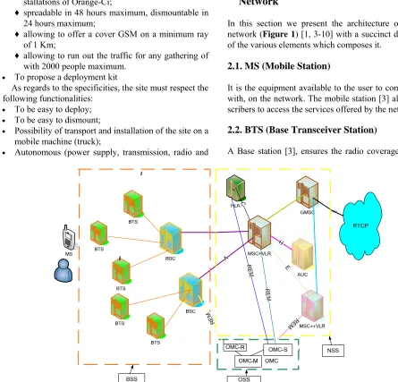
In this section we present the architecture of a GSM network (Figure 1) [1, 3-10] with a succinct description of the various elements which composes it.
2.1. MS (Mobile Station)
It is the equipment available to the user to communicate with, on the network. The mobile station [3] allows sub- scribers to access the services offered by the network.
2.2. BTS (Base Transceiver Station)
[image:2.595.54.499.275.702.2]A Base station [3], ensures the radio coverage of a cell
(basic unit for the radio coverage of a territory) of the network. It provides an entrance point in the network to the subscribers present in his cell to receive or transmit calls. The basic radio station manages the following op-erations: radio allocation of resources, regulation of the power of emission of the mobile station, measures qual-ity of the radio contact.
2.3. BSC (Base Station Controller)
A controller of base station BSC [3] manages one or more stations and fulfills various missions as well on the level of the communication as of the exploitation.
For the functions of the communications of the signals coming from the base stations, the BSC acts as a concen- trator since it transfers the communications coming from the various base stations towards a single output. In the other direction, the controller switches the data towards the correct base station.
At the same time, the BSC fulfills the role of relay for the various alarms intended for the center of exploitation and maintenance. It feeds also the database of the base stations. Lastly, a last important functionality is the radio resource management for the covered zone by the vari- ous base stations which are connected to it.
2.4. MSC (Mobile Switching Center)
It is the switching of the call center. On the one hand it allows making the connection between the GSM network and the switched telephone network PSTN / ISDN and on the other hand it serves as an interface between data- bases and the radio subsystem [3].
2.5. HLR (Home Location Register)
It is the central database containing information relating to any subscriber authorized to use the network. So that the data are consistent across the network, it serves as a reference for other local databases [3,11].
2.6. VLR (Visitor Location Register)
The VLR [3,11] is a temporary database containing in- formation on all users (Mobile Stations) in a given region, and in general it is integrated into the Mobile Switching Center (MSC).
2.7. AUC (Authentication Unit Center)
It is the authentication center services. It memorizes for each subscriber a secret key used to authenticate the re- quests for services and for the encrypting communica-
tions. An AuC is typically associated with each HLR [3].
2.8. EIR (Equipment Identity Register)
Despite the mechanisms introduced to secure the net- work access and the contents of communications, the mobile phone must potentially be able to accommodate any SIM card of any network. It is thus conceivable that a terminal can be used by a thief without not being able to be located. To combat this risk, each terminal receives a unique identifier IMSEI (International Mobile Station Equip- ment Identity) that cannot be changed without altering the terminal. According to data about a terminal, an op- erator may decide to deny access to the network. All op- erators do not implement such a database [3].
3. Technical Analysis of Radio Coverage
3.1. Study of Immobile Radio Operator Site
Here we present the general architecture (Figure2) of an immobile radio operator site and the description of the various elements which composes it.
A motionless radio site consists of four building blocks. We have: infrastructures, installations and energy equipment, installations and radio equipments and instal- lations and equipment of transmission. In the following we will conduct a study of the various functional blocks.
3.1.1. Infrastructures
3.1.1.1. The Shelter:
The shelter can be a house, a prefabricated shelter com- monly known as shelter (indoor site) or a roof with four poles (outdoor site). Its role is to protect the equipment against the sun and rain.
3.1.1.2. The Support
The support has a role to allow the installation of the air equipment. It can be a pylon or a mast. In the case of a pylon, it can be guyed or self-stable. The guyed pylon uses guys to be able to stabilize itself, which requires the definition of a ray of guy whereas the self-stable pylon self-stabilizes by frames.
3.1.1.3. The Cable Trays
Cable trays are used as passage with the cables. They also protect them. The cable trays consist of an horizontal part and of a vertical part but for a question of estheteics the vertical part was not represented on the diagram.
3.1.2. Installations and Radio Equipments
4 U Installation source
primaire
BAIE
ENERGIE BTS
Installations et equipements
energie
Abri Chemin de
cables Bretelles
basses
Bretelles hautes Antenne panneau
Support
Puit de terre R eglage tilt
m閏anique
Parafoudre
Cable
閚ergie
F eeder ID U
ODU
Cable KX13
Antennes faisceau
Primary source
installation
Installat ion s and ene rgy equipments
Mechnical tilt adjusting
Panel antenna
Lightning arrestor
Beam antenna
High straps
Support Energy
cable
Energy
rac k
Shelte r Low straps Tray of cables Feeder KX13 cable
[image:4.595.104.499.80.417.2]Ground well
Figure 2. Architecture of an immobile radio site.
with the users of the network. It consists of several ele- ments.
3.1.2.1. The BTS
Its role is processing the radio signal to be transmitted or received through the various electronic modules it con- tains. It also provides control of the mobile station. Traf- fic capacity of a BTS is defined by the number of trans- mitters / receivers (number of TRX) that are installed.
3.1.2.2. The Equipment of the Line of the Antenna
The straps
These are coaxial cables of transition with 50 Ω of im- pedance that can make the connection between the BTS and the feeders (low straps) and between feeders and the antennas (high straps). The straps must be shortest possi- ble to avoid the losses. The low straps are flexible and have a length of 3 m. However the high straps are rigid with a length of 2 m.
Feeders or coaxial cables
They constitute the principal supports of connection be- tween the BTS and the antennas. They are used as con- nection between the high straps and the low straps and
make it possible to forward the radio waves of the one of the straps to the other. Various types of feeders are used according to radio operator engineering taking account of the heights of the antennas. Thus we have the cables “7/8” and the cables “1 1⁄4” The feeders “7/8” are used when the height of the antennas is below 50m and with beyond one uses the feeders “1 1⁄4”.
Panel antennas
They allow to radiate in space the radio waves in desti- nation of the users or to collect those coming from the users. The antennas are installed with a height called HBA, according to an azimuth, a mechanical tilt signal and an electric tilt signal specified in the radio engineer- ing of the site. They are of type 900 MHz, 1800 MHz or 900 - 1800 MHz (Dual-band) according to the waveband used on the site. The main suppliers of Orange-Ci anten- nas are KATHREIN, JAYBEAM, POWERWAVE. In general, the principal characteristics for the choice of an antenna are: profit, the horizontal aperture, the vertical aperture, impedance, polarization and power.
the connection between the BTS and its BSC attachment called Abis link. The main equipments used are the equip- ments of radio-relay system but on certain sites we use optical fiber, leased lines or satellite connections. The capacity of Abis link depends on the capacity on radio operator of the site. Thus for the ALCATEL equipments used by Orange, 12 TRX to a Abis capacity of 2 Mbits/s (1 E1) corresponds. Thus in general on the Orange-Ci sites we have 1 E1 or 2 E1.
3.1.4. Installations and Energy Equipments
The installations and energy equipments have the role to provide necessary energy to the operating of the site.
3.1.4.1. Primary Energy
It is provided by an installation of the CIE (Ivorian Company of Electricity) or a generator. The power and the type of installation are given according to the power required on the site. The Orange sites have a three-phase connection of 30 A for the sites indoor and 20 A three- phase for the outdoor sites.
Primary energy can be also a renewable energy source (solar panels, wind energy, etc). Orange deploys already on its network the solar stations.
3.1.4.2. Secondary Energy
If primary energy is an alternative source (by CIE or Generator), the derived energy of 48 V DC is obtained after transformation in a bay energy of primary energy. The bay is composed of converter AC\DC, a system of battery and an unit of management. Branches batteries (4 batteries of 12 V) of 48V are installed in bay to be used as backup in the event of cut of the primary source. The autonomy of the batteries of the Orange-Ci sites is 08 hours on average.
If the primary energy source is a solar station, the equipment is directly supplied with 48V DC via a box of regulation. The backup is also ensured by a system of batteries.
3.1.5 Security of the Site
All the indoor and outdoor equipments will have to be connected directly and individually to the electric mass barrettes by a green/yellow cable of 50 mm2. The earth barrettes allow the equipotential bonding between vari- ous earthings.
All the metal parts attached to the pylon, such as metal ladders, safety rails, the cable channel and arm swing must be connected to the descent lightning arrestor to the high point and low point.
A protecting device against the lightning must to be envisaged on all the high buildings of which the height is higher than 25 m. Two types of lightning conductors are
used for this purpose. We have: lightning rods and meshed cage lightning conductors. A descent lightning, intended to run out the lightning current towards the meeting point is realized using a tinned copper flat of section 30 × 2 mm2 or round of section 50 × 2 mm2 placed always out- side.
The meeting point is realized to improve the value of the ground which must be lower or equal to 10 Ω. The conductors used for the constitution of the meeting point must be from the same section and the same matter as those used for the descent lightning. According to the configuration of the site various techniques are used for the realization of the meeting point.
3.2. Study of a Movable Radio Site
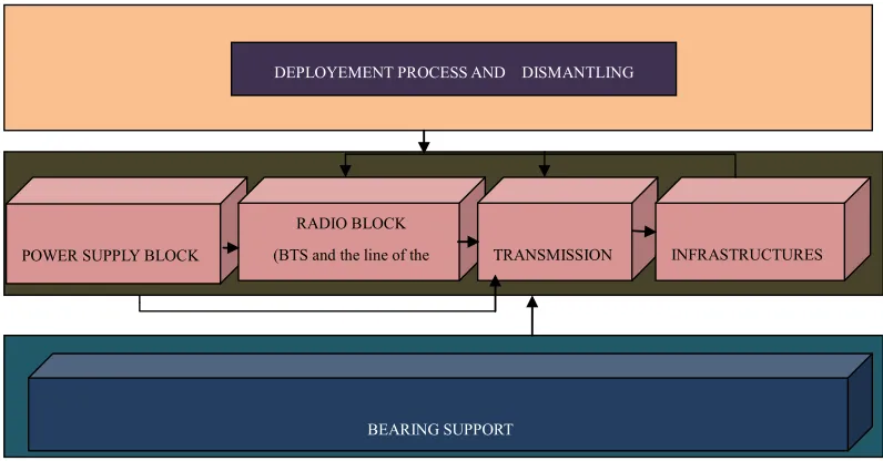
The Figure 3 below illustrates the synoptic presentation of a movable radio site. It is composed of different parts to dimension: 1) the radio block, is the part that will make the connections in the radio coverage zone of the movable site; 2) the transmission block is the part which will enable us to establish the Abis interface between the movable site and its BSC of attachment, 3) the power supply block is the part which must provide necessary energy to the operation of the site, 4) the infrastructures, they are the infrastructures necessary to the installation of the equipments and 5) the bearing support, it is the support on which the equipment will be installed. It is this item that will give the function of mobility to the site thus giving it the character of movable radio site mobile.
For the good implementation of all its parts it will be necessary to define, a procedure of deployment and dis- assembling, it indicates the different steps of deployment and disassembling of the movable radio site.
4. Technical Solutions and Discussion
4.1. Radio Solutions: Dimensioning, Choice and Design of Base Station
4.1.1. Concepts of Traffic and Dimensioning
In a GSM network, it is however not only to guarantee a radio link, but also to guarantee a certain traffic. The traffic is estimated statistically from the population den- sity and the type of activity associated with each region. For example, the probability of call in a zone with high housing density is very different from the probability call in a zone with high density of occupation. Erlang laws [12,13] are used to characterize the rate of phone calls. This law is parameterized by two parameters: the rate of call μ, and the average duration of call H. The intensity of traffic per user is expressed by:
(erlang) v
BEARING SUPPORT
POWER SUPPLY BLOCK
RADIO BLOCK
(BTS and the line of the
TRANSMISSION INFRASTRUCTURES
[image:6.595.98.496.78.286.2]DEPLOYEMENT PROCESS AND DISMANTLING
Figure 3. Synoptic presentation of a movable radio site.
Knowing the population density associated with a geo- graphical zone, it is easy to determine the traffic density by:
2
(erlang/Km ) H
v
AA d (2) where dH is the population density per Km2.
Lastly, if one is able to predict the covered zone by a cell, it is then possible to estimate the traffic that the cell must absorb:
(erlang) tot
A A S (3) where S is the area of the cell.
Erlang laws allow then determining the number of channels required to absorb this statistical traffic with a given failure rate. The B. Erlang [13-15] law is given by the following formula:
0 1
! 1 ! Nc tot
C C
C n
n
A N P
N A
n
(4)
where NC is the number of voice channels.
Thus, from the knowledge of the traffic density and the surface covered by a transmitter, it is possible to pre- dict the number of channels to be assigned to a cell to guarantee a blocking rate below a certain percentage, for example 2%.
We understand well whereas the deployment of a network GSM is not based on a radio coverage but on an intelligent distribution of the radio resources on a set of base stations.
The number of voice channels available is not equal to the number of frequency channels. For each cell, it is necessary to reserve a beacon channel which contains the
synchronization channels (FCH, SCH, and BCCH) [3, 14,15]. These channels allow the mobiles to detect the presence of the base stations. During the attribution of a certain number of frequencies at a base station, it is thus necessary to eliminate one from the frequencies to count the radio resources.
In addition, each frequency channel is likely to pro- vide 8 channels of data TCH [14,15]. The total number of channels is thus equal to 8 times the number of fre- quency channels.
However, certain common channels, and in particular the beacon channel, require resources. It is considered in general that 1/8th of resources is used for the common channels (including the beacon channel).
Thus, for N channels assigned to a base station, the number of TCH (NTCH) is given by:
7 8
TCH
N N (5) If Nf is the number of carriers assigned, then the num-ber of physical channels TCH [14,15] available is:
7
C f
N N (6)
4.1.2. Dimensioning of the TRX of the BTS and the Choice of the BTS
2000*14.5 mErlang, i.e. 29 Erlang. The Equation (4) of B Erlang law indicates 6 TRX to run out this traffic. We decided to add 2 TRX like margin. Thus in total our site will include 8 TRX. We can thus plan to use a MBI3 ALCATEL BTS or MBO1. We suggest a BTS MBO1 Alcatel.
4.1.3. Design Study: Dimensioning of the Radio Coverage
The movable site must offer a radio coverage on a mi- nimum ray of 1 km.
4.1.3.1. Choice of the Waveband
Considering the ray of cover whose minimum is of 1 km, our movable site can use frequencies 900 MHz or 1800 MHz according to the constraints of our existing plan of frequency. We thus recommend 1800 MHz band for the dense-urban zones (objective of traffic) and 900 MHz band for the urban and rural zones (coverage objective).
4.1.3.2. Choice of Radio Equipments
Solution with the ordinary equipments:
The BTS: a BTS MBO1 in 1800 MHz band or 900 MHz band is thus adapted to the mobile radio site. Indeed the MBO1 is designed to be installed in out- door environment and can support up to 8 TRX and its consumption is less.
The TRX: to limit the energy consumption and the interferences that could cause the site, especially in the case of densification we chose TRX TRADE 1800 MHz and 900 MHz which are TRX of medium power.
Choice of cables: In the deployment of the immobile sites, the cables generally used are the coaxial cables. Two types of coaxial cables are used:
The “7/8” cables for antenna heights below 50 m.
The “1 1/4” cables for antenna heights beyond 50 m.
As we will not have heights of antennas beyond 50 m considering the ray of cover is only of 1 km we thus choose coaxial cables of the “7/8” type.
Choice of the panel antenna: Using 2008 Catalog of the antennas of KATREIN we chose the K742196 panel antenna of KATHREIN because of its charac- teristics that are here:
♦ Waveband: 915 - 990 MHz; 1710 - 1880 MHz ♦ Polarization : +45˚,–45˚
♦ Gain : 2*15.3 dBi
♦ Horizontal opening angle: 67˚
♦ Vertical opening angle: 12.6˚
♦ Impedance : 50 Ω ♦ Maximum power: 300 W
Solution with a distributed BTS:
For a movable site, we wish that it be the most flexible and that it consumes less. The cables for the intercom- necttion of the radio operator equipment must be flexi- ble and easy to handle. The use of a MBO1 does not seem to us suitable considering this one uses coaxial ca- bles which are rigid, heavy and sometimes cumbersome. This is why we recommend the use of a distributed BTS for the realization of the movable radio site. Indeed the distributed BTS uses optical fiber for the interconnection of the radio equipment and it has also the advantage of consuming less. The solution with the distributed BTS will be thus the principal solution which we adopt.
Configuration of the mobile site: The site will be by default a tri-sector site with the S332 configuration. The number of final sector and the configuration will be defined by a Design study which will be con- ducted during the deployment.
Design radio parameters: These are the antenna heights, azimuths, tilts of mechanical and electrical and GPS coordinates of the site [16,17]. These pa- rameters are defined according to the objectives of coverage and the location of the site affecting its re- lief. Since the location of the movable site is not known a priori (changeable locations), we cannot de- fine these parameters. However regarding the heights of antennas we have with the software ASSET set an estimated value to enable us later to define the length of the pylon. With the software, we set the design pa- rameters and we evaluate the radius of coverage ob- tained. We specify that in this simulation azimuths and tilts have been taken arbitrarily, the most impor- tant being the height.
4.2. Choice of the Transmission Technology
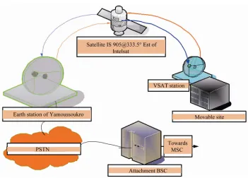
Among the different technologies of transmission, we chose a solution by satellite which supposes the exis- tence of a satellite link that we will be able to exploit. At this level, it should be noted that Ci-Telecom (the PSTN operator in Ivory Coast) has a satellite link and consid- ering Orange-Ci and Ci-Telecom merged we can use this link. A transmission by satellite through a VSAT [18] proves to be flexible, requesting less infrastructures and easy to implement. The installation of a station VSAT can be done in half-day, as well disassembling. This so- lution seems to us adapted, it will thus be adopted. It constitutes our main solution. However in the case of deployment of the movable site in the big cities where exist BSC sites, the solution by radio-relay system can be considered if it does not require several hertzian jumps.
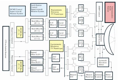
station of Yamoussoukro and the national transmission network (Ci-Telcom) already existing. A station VSAT will be installed at the movable site location (see Figure 4-5). It will communicate with the earth station of Ya- moussoukro (Figure 6) through satellite IS [email protected] of Intelsat. The earth station of Yamoussoukro is con- nected to the national transmission network (Ci-Telcom) as well as the various BSC of Orange-Ci. The traffic could thus be conveyed until the attachment BSC se- lected. The attachment BSC will be selected according to the locality in which the deployment takes to allow the realization of the Handovers. But for the deployments in remote zones, i.e. zones where the mobile site will not have contacts of vicinity, we suggest that we choose one of the three BSC of Yamoussoukro, considering their proximity of the earth station of Yamoussoukro. The radio equipment (BTS, TRX and cables) will be replaced by the solution of distributed BTS if it is available at the time of the implementation of the solution.
The earth station of Yamoussoukro (Figure 5) was in- stalled in 2000. It consists of a parabolic antenna of 21 m in diameter and several modems and satellite control equipment [18]. The station operates in the C-band, 5.856 - 6.425 GHz in emission and 3.625 - 4.2 GHz reception. It is as follows.
4.2.2. Configuration of the Movable VSAT Station
The bit rate of the station: It is question to estimate the speed necessary to the flow of the movable site traffic. The mobile site will be composed of 8 TRX. To run out the traffic of such a site, an E1 link is suf- ficient, which fixes the bit rate of the VSAT station at 2 Mbits.
Type of modulation: In the field of the transmission by satellite, several types of modulation are used. The choice of a kind of modulation is done according to the bit rate, of the FEC (Forward Error Correction) [19,20]and of the spectral effectiveness. To reduce
M O D U L A T E U R B U C
D EM O D U L A T E U R L N B
O M T P AR A B O L E D O N N E E
S A E M E T T R E
D O N N E E S R E C U E S
ID U O U M o d e m sa t e lli te
O D U
Data to transmit
Data to receive
Modulator BUC
Demodulator LNB
OMT Parabola
[image:8.595.117.499.319.419.2]ODU IDU or Satelitte modem
Figure 4. Diagram of a VSAT station.
[image:8.595.122.473.453.705.2]Figure 6. Synoptic diagram of the earth station of Yamoussoukro.
the band-width necessary to the flow of traffic and to avoid an underdevelopment of speed we wish a mo- dulation which has a spectral effectiveness and a bit rate fairly high. We thus choose a modulation 8-PSK [21] with a FEC of 2/3 because this modulation offers a not too high flow and a relatively high spectral ef- fectiveness which enables us to reduce the band- width to allocate and thus the cost of hiring of this one. In the same way it is the type of modulation re- commended by the study made by METRACOM for Orange-Ci within the framework of the project of Abis connection by satellite. We chose the modula- tion 8-PSK which has a spectral effectiveness of 3bits/s/Hz and the bit rate of the station is 2 Mbits/s. We point out that the spectral effectiveness is defined by: necessary bit rate /Band-width. For 2 Mbits/s it is necessary thus to have a band-width of 0.35 MHz. The minimal value of allowable band-width to an op- erator by Intelsat being of 1MHz, we retain 1MHz like band-width.
The satellite modem (Indoor Links (IDU)): Our choice was made on the equipment of the Comtech type more precisely the Comtech-570 L modem. Indeed this equipment was already used in similar projects
carried out in other countries. Also they are used at the earth station of Yamoussoukro; there is thus competence in their use. Beyond all that the Com- tech-570L modem presents many other advantages such as the presence of Ethernet port, the possibility of varying from type of modulation etc. which en- ables it to be adapted to various types of applications. The features of the satellite modem Comtech-570L are the following:
♦ Bite rate : 2.4 Kbs to 9.98 Mbs
♦ Type of modulation: BPSK, QPSK, 8-PSK, 8-QAM ♦ Interfaces: T1/E1, 10/100 Base T-Ethernet
♦ Quality of service: Optionnel
♦ Compression of headers and useful message ♦ Operating temperature: 0 to 50˚C
♦ Power supply: 220V/50 to 60 Hz ♦ Maximum power: 300 W
VSAT Parabola: We chose the Prodlin parabolas marketed by company EDDISTON SBS. Indeed these parabolas offer an excellent profit and are adapted perfectly to the C band in which our station must function. VSAT Parabola will have a diameter of 2.4 m. These features are:
♦ Gain: 42 dB (the maximum)
♦ Frequency of emission: 5.856 - 6.425 GHz ♦ Frequency of reception: 3.625 - 4.2 GHz ♦ Diameter of the parabola: 2.4 m
The satellite compass: The satellite compass is used to locate the satellite to allow a better pointing of the parabola. We choose the satellite compass of Met- ronic.
The satellite pointer: Its role is to allow the orienta- tion and the precise chock of the parabola. For the satellite pointer our choice was made on the satellite pointer Wiltek 9103 of Wiltek. Indeed this satellite pointer also allows making radio measures in the wavebands of the GSM and the DCS. These features are the following:
♦ Minimum Bandwidth (Hz):100 KHz ♦ Maximum Bandwidth (Hz):7.5 GHz ♦ Minimum Amplitude (dBm): –120 dBm ♦ Maximum Amplitude (dBm):+20 dBm
♦ Bandwidth of minimum resolution (RBW) (dB; Hz)
♦ Trip frequency (Hz):0 Hz, 10 kHz and 7.5 GHz ♦ Video Filter (Hz):10 Hz - 1 MHz
♦ Delivered with: power supply, CD containing the handbook and the software of transfer of informa- tion
♦ Dimensions (H × W × D) (mm): 190 × 355 × 104 mm
♦ Net weight (kg): 3.6 kg
The satellite portable: it is essential in the deploy- ment of a movable radio site. Indeed at the time of the commissioning the agent of the OMC-R on the site must communicate with that which is on the level of the OMC-R. Considering the movable site will be de- ployed in zones not often covered, the satellite port- able will allow to establish this communication. Any satellite portable is adapted.
GPS receiver: The GPS receiver will allow to deter- mine the GPS position of the location where the site will have to be installed, which will allow to deter- mine the transponder for which the traffic will be conveyed.
4.3. Energy Solutions
4.3.1. Choice of the Option of the Power Supply The generator offers many advantages for the primary
energy supply of a movable radio site. Indeed the gen- erator is easily transportable; it is robust what enables it to resist many displacements. Our choice was thus made on the generator. The generator constitutes the principal solution; however in certain cases in particular for the thickenings in Abidjan one will be able to use a source of CIE or a solar panel.
4.3.2. Assessment of Energy and Dimensioning of the Energy Workshop
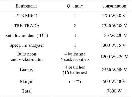
4.3.2.1. Assessment of Energy
The following Table 1 presents the assessment of power which is the power necessary to the operation of all the equipment installed on the site [22,23]
4.3.2.2. Dimensioning of the Energy Workshop
To dimension the energy workshop we will consider only the equipments which functions under the tension 48 V. The power of these equipments is evaluated at 5650 W/48 V. Thus two rectifiers of the 3200 W/48 V type can thus make it possible to provide such a power.
A rectifier will be intended for the power supply of the equipment
A rectifier for the charge of batteries
For the question of emergency we envisage a third standard rectifier in the same way.
Finally the workshop energy will be composed of 3 rectifiers 3200 W/48 V and 4 branches of battery
[image:10.595.309.538.555.723.2] Evaluation of the primary power and dimensioning of the generator: The evaluation of the primary power takes into account all the put powers concerned [22,23]. This power is an active power. The power of the generator is the corresponding apparent power: Pp = Prectifiers + P220V = 3200 × 2+ 1200 = 7600W where Pp corresponds to the active power. It is thus nec- essary to determine the apparent power (S), One a:
Table 1. Assessment of power.
Equipments Quantity consumption
BTS MBO1 1 170 W/48 V
TRE TRADE 8 2240 W/48 V
Satellite modem (IDU) 1 180 W/220 V
Spectrum analyzer 1 300 W/15 V Bulb neon
and socket-outlet
4 bulbs and
4 socket-outlets 1200 W/220 V
Battery (16 batteries) 4 branches 2560 W/48 V
Margin 6.57% 500 W/48 V
Pp = S·cos(Φ), this implies that S = Pp/cos(Φ) = 7600/0.86 = 8.53 KVA.
The standardized power nearest is 10 KVA. But in the range of the generators of the Orange-Ci suppliers the 10 KVA are not equiped with automatic starting. This is why we suggest a group of 12 KVA. To feed such a group during six days we envisage a cistern of 500 liters. The generator must be a silent group to prevent that this one does not disturb by its noise.
Evaluation of the autonomy of the batteries: The quantity of electricity (Q) is:
Q I t, now P U I U Q t
thus t U Q
P
, we
also know that:
1 Ah = 3600C for a battery. Four branches of battery provide:
Q = 4 × 160 × 4 × 3600 C = 9216000 C
The batteries supply only the equipment 48 V whose required power was estimated at 3200 W. Thus:
48 9216000 138240 38.4 1.58
3200
t s hours days
Choice of the generator: The selected generator is that of SDMO company considering the robustness of this one. It was several times used on the Orange-Ci sites. This generator SDMO is of 12 KVA.
4.3.2.3. Study of the Environment
For earthing of the equipment, it will be installed a bar of ground on one side of the truck. All earthings will con- verge towards this bar of ground using green yellow ca- bles or flat part for the descent lightning protector. Thereafter the ground bar itself will be connected to the ground stake by a naked cable, HFG cables. The ground stake will have to be installed far from the place of in- stallation of the equipment.
4.4. Bearing Support and Infrastructures Solutions
It is question of defining the various infrastructures nec- essary to the installation of the equipments of the radio site. The study of radio design suggested a solution out- door; it is a solution with a truck with leaves which is retained.
It is question of using a truck with two side leaves. This solution enables us to make safe the equipments during their transport avoiding dust and the rain. We envisage a space on the truck to shelter the generator and the cistern of 500 L. For this, once on the place of de- ployment, we open the two side leaves and the installa- tions can then be done in an environment outdoor. Finally this solution will be the solution which we adopt.
Study of the antenna support: The various forms of mediums generally used for the installation of anten- nas GSM are:
♦ Stayed or self-stabilizing pylons ♦ Mast
Use of a pylon: The use of a pylon in the deployment of a mobile site does not prove suitable sight the size of this one and time that it is necessary to build it. In the same way the pylon requires many constraints (solid mass, staying, etc.) for its installation. We can- not thus use a pylon.
Use of a mast: The Mast contrary to the pylon is smaller and requires less requirements for its installa- tion. It can easily be installed on a truck. We thus re- tained a Mast for the support of antennas GSM. The Mast to be conceived must have the following char- acteristics:
To be able to support three antennas panels of the K742196 type.
To be controlled by an automated system which en- ables it to leave and to line up
We recommend a mast of 25 m height considering the results the estimated height of the antennas obtained in radio engineering.
4.5. Deployment Kit of the Event-Driven Movable Radio Site
The list of the components of the kit of deployment of the event-driven movable radio site is presented as fol- lows:
A truck with two side leaves.
A BTS MBO1 or a distributed BTS according to the availability
6 × 30 m of coaxial cables “7/8” or optical fibers ac-cording to the solution.
Four rollers of cables
A GPS receiver of any type
A compass satellite of Metronic
Wiltek 9103 satellite pointer
The kit of VSAT station (Modem, parabola and ex-ternal unit).
Fuel to feed the group
All accessories for earthing of the equipments
A satellite portable of any type.
A 12 KVA generator of SDMO type
A cistern of 500 L of any type
Energy cables of section 50 mm2
Panels antennas of the K742196 type
3 panels antenna bases
3 rulers of mechanical tilt
3 supports of arrangements of panels antennas
all type + 1 Emerson bay
An inclinometer
Hiring of the band of 1 MHz
5. Conclusions
This work enabled us to propose a kit for the deployment of a movable radio site for opening or temporarily mak- ing denser the Orange-Ci network during the significant events in a given locality. We proceeded in a first under investigation of the motionless radio sites which enabled us to emphasize the various building blocks as well as the various equipments used for their deployment. There- after we conducted a study on various building blocks within the framework of the deployment of a movable radio site to lead to the proposal of a deployment kit of the movable radio site.
In Perspective, this work can be directly exploited by another GSM operator in Ivory Coast. We will write the procedure for the deployment of the movable radio site and its dismantling.
6. References
[1] J. Zhang and I. Stojmenovic, “Cellular Networks,” Wiley, Hoboken, 2005, pp. 654-663.
[2] L. da Silva, T. Belleli and S. P. Harris and A. CET, “A Decision Support System for Planning GSM Radio Cov-erage,” IEEE Colloquium on GSM and PCN Enhanced Mobile Services, London, 30 January 1991, pp. 1-4.
[3] M. Mouly and M.-B. Pautet, “The GSM System for Mo-bile Communications,” Telecom Publishing, Washington, DC, 1992.
[4] U. Black, “Mobile and Wireless Networks,” Prentice Hall, Upper Saddle River, 1996.
[5] U. Black, “Second Generation Mobile and Wireless Net- Works,”Prentice Hall, Upper Saddle River, 1999 [6] C. Bettstetter, H. Vogel and J. Eberspacher, “GSM Phase
2+ General Packet Radio Service GPRS: Architecture, Protocols, and Air-Interface,” IEEE Communications Survey,Vol. 2 No. 3, 1999.
[7] Y.-B. Lin and I. Chlamtac, “Wireless and Mobile Net- work Architectures,” John Wiley & Sons, Hoboken, 2001.
[8] D. P. Agrawal and Q.-A. Zeng, “Introduction to Wireless and Mobile Systems,” Brooks/Cole, Florence, 2002. [9] T. S. Rappaport, “Wireless Communications—Principles
and practice,Prentice Hall, Upper Saddle River, 2002. [10] W. Stallings, “Wireless communications and Networks,”
Prentice Hall, Upper Saddle River, 2002.
[11] J. Zhang, “Location Management in Cellular Networks,” In I. Stojmenovic, Ed., Handbook of Wireless Networks and Mobile Computing, John Wiley & Sons, Hoboken,
2002, pp. 24-49. doi:10.1002/0471224561.ch2
[12] L. Kleinrock, “Queuing Systems,” New-York Wiley, New York, 1976.
[13] G. Budura, C. Balint and A. Budura, “Radio Resources Dimensioning According to Different Allocation Strate- gies in GSM/GPRS Networks,” Proceedings of the 8th WSEAS International Conference on Computational in-telligence, man-machine systems and cybernetics, Puerto de la Cruz, 2009, pp. 168-174.
[14] B. Baynat, K. Boussetta, P. Eisenmann and S. Trabelsi, “Extended Erlang-B Law for Performance Evaluation of Radio Resources Sharing in GSM/(E)GPRS Networks,”
IEEE 16th International Symposium on Personal, Indoor and Mobile Radio Communications, Berlin, 11-14
Sep-tember 2005, pp. 1713-1718.
[15] P. Stuckmann and O. Paul, “Dimensioning Rules for GSM/GPRS Networks,” Proceeding of the Aachen Sym-posium on Signal Theory, Aachen, 2001, pp. 169-174. [16] G. E. Aderibigbe, M. O. Kolawole and V. S. A. Adeloye,
“Effects of Antenna Tilting on Transmitting Power in Mobile Cellular Communication Systems,” International Journal of Communications, Network and Systems Sci-ences, Vol. 4, No. 7, 2011, pp. 464-467.
doi:10.4236/ijcns.2011.47056
[17] M. V. S. N. Prasad, M. M. Gupta, S. K. Sarkar and I. Ahmad, “Antenna Beam Tilting Effects in Fixed and Mobile Communication Links,” Current Science, Vol. 88,
No. 7, 2005, pp. 1142-1147.
[18] M. O. Kolawole, “Satellite Communication Engineering,” Marcel Dekker, New York, 2002.
doi:10.1201/9780203910283
[19] V. Lakkundy and M. Kasal, “FEC for Satellite Data Communications: Towards Robust Design,” AIC’04 Proceedings of the 4th WSEAS International Conference on Applied Informatics and Communications, Stevens,
2004.
[20] J. Hagenauer, E. Lutz, “Forward Error Correction Coding for Fading Compensation in Mobile Satellite Channels,”
IEEE Journal on Selected Areas in Communications, Vol.
5, No. 2, 1987, pp. 215-225. doi:10.1109/JSAC.1987.1146523
[21] D. Wu, X. Gu and Q. Guo, “A Novel Adaptive Classifi-cation Scheme for Digital Modulations in Satellite Com-munication,” High technology letters, Vol. 13, No. 2,
2007, pp. 145-149.
[22] O. Arnold, F. Richter, G. Fettweis and O. Blume, “Power Consumption Modeling of Different Base Station Types in Heterogeneous Cellular Networks,” Future Network and Mobile Summit 2010 Conference Proceedings,
Flor-ence, 16-18 June 2010, pp. 1-8.
[23] F. Richter, A. J. Fehske and G. P. Fettweis, “Energy Effi- ciency Aspects of Base Station Deployment Strategies in Cellular Networks,” Proceedings of the 70th IEEE Ve-hicular Technology Conference, Anchorage 20-23