Nanostructured L1
0Fe–Pt Based Thin Films
for Perpendicular Magnetic Recording
Toshio Suzuki
AIT (Akita Research Institute of Advanced Technology), Akita 010-1623, Japan
Aiming at development of ultra-high density magnetic recording media, nanostructured Fe–Pt perpendicular recording media were tailored. In order to obtain a crystal orientation of Fe–Pt(001) for a double-layered perpendicular medium with a soft-magnetic underlayer, a heteroepitaxial layer configuration was applied. A high pressure sputter-deposition method was effective for lowering the fct-ordering temperature of the L10crystal structure. Microstructures of the media were constructed by two kinds of methods,i.e.inducing crystal defects and forming composite films with oxides. The highest SN ratio was obtained by a wall pinning type medium with the induced crystal defects. Design and possibility of the Fe–Pt(001) media were discussed.
(Received June 30, 2003; Accepted July 8, 2003)
Keywords: iron-platinum, L10, microstructure, nanogranular, ordering, perpendicular recording media, wall pinning
1. Introduction
Magnetic recording technology is currently heading for the achievement of areal recording densities beyond 310 Tbit/ m2. Perpendicular magnetic recording is a promising candi-date for the ultra-high density recording. However, it becomes harder for conventional Co–Cr based granular type media to fulfill all requirements of higher recording and reproducing resolutions, lower media noise and thermal stability of recorded bits.
The perpendicular magnetic recording is fundamentally characterized by demagnetizing field-free transitions.1)This principal feature is a great advantage not only for the granular type media but also laterally exchange-coupled film media with enhanced wall-pinning effects.2,3)Recently, it has been reported that larger saturation magnetization and uniaxial magnetic anisotropy, high density pinning sites and a thinner thickness of the recording layer are material requirements for the wall-pinning type media.4)In those media, both a larger slope parameter of a hysteresis loop and a smaller domain size would coexist, thus, higher recording and reproducing resolutions and lower media noise are expected to be realized.
Among permanent magnetic materials, an ordered FePt intermetallic compound has the most advantageous features of an extremely large uniaxial anisotropy energy,5,6)a large saturation magnetization, and a high corrosion resistivity. Therefore, the ordered FePt thin film with perpendicular magnetic anisotropy has possibilities not only of the granular type but also the wall-pinning type media.
In this paper, a layer configuration and a high pressure sputter-deposition method are shown for the preparation of Fe–Pt perpendicular double-layered recording media. Fur-thermore, microstructures and possibilities for high density recording are also presented.
2. Preparation of Fe–Pt(001)
2.1 Layer configuration for Fe–Pt(001) media
Ordered Fe–Pt thin films with perpendicular magnetic anisotropy were so far prepared at temperatures over 773 K
using a single crystal MgO substrate by postannealed sputtered Fe/Pt multilayers,7) molecular beam epitaxy,8) cosputtering,9) monoatomic multilayers using ultra-high vacuum evaporation,10)conventional sputtering11)or electron beam vacuum evaporation.12,13)
For the application to magnetic recording media, an ordered Fe–Pt(001) film was first reported using a glass substrate by a high pressure sputter-deposition method with a heteroepitaxial technique using a Cr-underlayer/MgO-seed-layer.14)Furthermore, a perpendicular double-layered media construction with a soft-magnetic underlayer was also proposed.15)
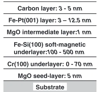
Figure 1 shows a schematic drawing of the double-layered Fe–Pt medium with an Fe–Si soft-magnetic underlayer of a saturation magnetic flux density,Bs, of 1.8 T as a backlayer. Each layer of this construction was heteroepitaxially stacked to realize the Fe–Pt(001) orientation, e.g., bcc(100) crystal orientations of the Cr underlayer and Fe–Si soft-magnetic underlayer were set by the MgO seed-layer with the (100) crystal orientation, as shown in Fig. 2. An ultra-thin MgO intermediatelayer was able to be applied by the effect of the heteroepitaxial growth on the Fe–Si layer with the (100) crystal orientation.
Substrate
MgO seed-layer:
5 nm
Cr(100) underlayer: 0 -
70 nm
Fe-Si(100) soft-magnetic
underlayer:
100 - 500 nm
MgO intermediate layer:
1 nm
Fe-Pt(001) layer:
3 – 12.5 nm
Carbon layer:
3 - 5 nm
[image:1.595.338.511.603.766.2]The MgO intermediate layer fulfilled two important roles in the double-layered configuration. One was for the improvement of the crystallinity of an initial growth layer in the Fe–Pt(001) layer.16)The other was for the elimination of an interlayer exchange-coupling between the Fe–Pt and Fe–Si layers,15)which was shown in the magnetic property for the Fe–Pt layer. As seen in Fig. 3, introducing the MgO intermediate layer resulted in the rectangular shaped Kerr effect hysteresis loop without steps in the second and fourth quadrants. Finally, the Fe–Pt layer of 5 nm thickness was proven to act as an ultra-thin recording layer with sufficient thermal stability.16)
2.2 Low temperature fct-ordering for L10 structure Figure 4 shows the effect of a high pressure sputter-deposition method on perpendicular coercivities of Fe–Pt layers in the double-layered media. The Fe–Pt layers were prepared under the conditions of 50 Pa and 5 Pa by applying the sputtering targets of Fe50–Pt50and Fe55–Pt45, respective-ly, to allow a comparison at the same equiatomic film composition, because the content of Fe in the film increased with increase of the sputtering gas pressure.4)Judging from XRD data, the increase of coercivity with the rise in the
[image:2.595.86.252.69.243.2]preparation temperature was due to the increase in the amount of the formed Fe–Pt ordered phase with the fct(001) orientation. Accordingly, the high pressure sputter-deposi-tion method was very effective for lowering the ordering temperature. Using the sputtering pressure of 50 Pa, temper-atures of 573 to 673 K can be applied for the preparation of the ordered Fe–Pt perpendicular double-layered media and these are around 150 K lower than the temperatures for the condition of 5 Pa.
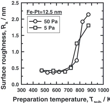
Figure 5 shows surface roughness,Ra, of the media with the Fe–Pt layers prepared in the conditions of 50 Pa and 5 Pa, where Ra is an average height of surface ups and downs measured by an AFM observation. In both the conditions, the
Ravalues increased with increase of the preparation temper-ature for the Fe–Pt layers, especially more than 773 K. The higher pressure conditions are desirable for the ordered Fe–Pt media with a very smooth surface, because the lower temperatures are applied for the ordering transformation, as shown in Fig. 4. On the other hand, the increase of Ra is thought to be caused by a grain growth of the Fe–Pt phase. In the condition of 5 Pa, both the grain growth and the ordering transformation rose at 773 K, while those in the condition of
2θ
20 30 40 50 60 70 80
Log (intensity) (arb. unit)
fct(001) MgO(200) fct(002) Cr(200) fct(003)
FeSi(200)
Preparation temp.= 573 K Sputtering pressure= 50 Pa
Fig. 2 XRD chart for double-layered medium. Fe–Pt = 12.5 nm, Fe–Si = 500 nm, Cr = 70 nm.
Applied Field, H / MA.m-1
-1.0 -0.5 0.0 0.5 1.0
Kerr rotation angle,
θ
k-0.6 -0.4 -0.2 0.0 0.2 0.4 0.6
#2 #1
#1: FePt(12.5 nm)/FeSi/Cr/MgO/Sub. #2: FePt(12.5 nm)/MgO(1 nm)/FeSi/Cr/MgO/Sub.
Sputtering pressure= 50 Pa Preparation temp.=573 K
Fig. 3 Polar-Kerr loops for Fe–Pt media.#1: without MgO intermediate layer,#2: with MgO intermediate layer.
Preparation temperature, Tsub / K
300 400 500 600 700 800 900 1000
Coercivity,
Hc
/ MA
.m
-1
0.0 0.2 0.4 0.6 0.8 1.0
Sputtering Pressure =50 Pa
5 Pa
Fe-Pt=12.5 nm
Fig. 4 Dependence of perpendicular coercivity on sputtering temperature for double-layered media.
Preparation temperature, Tsub / K
300 400 500 600 700 800 900 1000
Surface roughness,
R a
/ nm
0.0 0.5 1.0 1.5 2.0 2.5
50 Pa 5 Pa Fe-Pt=12.5 nm
[image:2.595.334.518.71.245.2] [image:2.595.81.257.299.467.2] [image:2.595.335.516.585.755.2]50 Pa did not simultaneously. This suggests that the ordering mechanism under the 50 Pa condition is different from that of 5 Pa.
To discuss the mechanism of the lower temperature ordering, crystallographic analyses by in-plane XRD meas-urements for the films prepared at 323 K are shown in Fig. 6. In the higher pressure conditions, the disordered phase was found to be of a crystal structure with dð001Þ=dð100Þ<1, where dðijkÞ is an interplanar spacing of (ijk) plane. In general, a high pressure condition induces a tensile stress in the lateral direction of the film.17) This means that a compressive strain is induced along the film normal. Thus, the disordered crystal structure with dð001Þ=dð100Þ<1 would be the result of the compressive strain along the film normal by the high pressure sputter-deposition method. In order to relax the stress under the compressive strain along the film normal, the disordered phase would easily transform to the ordered fct phase with c-axis along the film normal during the sputter-deposition process even at 573 to 673 K. It is safe to conclude that the lower temperature ordering by the high pressure sputter-deposition comes from strain-induced preferred phase transformation.
3. Microstructure Tailoring
3.1 Wall-pinning type Fe–Pt(001)
The microstructure of the double-layered medium pre-pared at the temperature of 573 K under the sputtering pressure of 50 Pa is shown in Fig. 7. The plan-view TEM image, (a), shows a well textured crystal structure with rectangularly arranged crystal defects. The defects were found to be along [110] and [110] directions, judging from the electron beam diffraction pattern. Besides, extra streaks in the diffraction pattern suggest {111} twins.18,19)As seen in the cross-sectional image, (b), the Fe–Pt layer was found to have very clear defect lines which inclined to the film normal. The angle between the defect lines and (001) plane parallel to the substrate is around 55. This corresponds to the angle between the (111) plane and (001) plane. Therefore, the inclined planar defects would be due to {111} twins, showing the extra steaks in the diffraction pattern.
In studies on the microstructure of bulk alloys with the crystal structure of L10type, planar defects are known to be spontaneously formed during the phase transformation from a disordered fcc phase to an ordered fct by annealing,20)and the defects are thought to act as pinning sites against wall propagations.21,22)
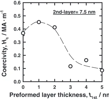
In order to induce numbers of crystal defects acting as wall-pinning sites, a two-step deposition method was proposed.23) In the method, a disordered Fe–Pt thin layer was made by a first-step sputter-deposition at 323 K, then an ordered Fe–Pt layer was grown by a second-step sputter-deposition at 648 K. When the disordered phase of the first deposited layer would be transformed to an ordered phase during the heating up to 648 K for the second-step deposition, numbers of crystal defects are expected to be introduced.
As shown in Fig. 8, preforming the 1 nm or 2 nm thick first-layer led to the increase in perpendicular coercivity of the total Fe–Pt layer. In addition, an MFM observation for an ac-demagnetized state showed that a domain size was 80 nm for the film with the 2 nm thick preformed layer, while 102 nm for the film without the preformed layer.23)These suggest that the density of pinning sites increased by the two-step method.
Ar sputtering pressure, P / Pa
0.1 1 10 100
Interplanar spacing,
d(ijk)
/ nm
0.35 0.36 0.37 0.38 0.39 0.40
(001) || Substrate by out-of-plane XRD
(volume)1/3
(100) ⊥ Substrate by in-plane XRD
Deposited at 323 K
Sputtering target: Fe50-Pt50
Fig. 6 Interplanar spacing of (001) and (100) planes for disordered films prepared at 323 K, measured by out-of-plane and in-plane XRD, respectively. Dotted line is volume average of d(001) and d(100).
(a)
(b)
111T
110
20
0
20 nm
Fig. 7 TEM images of Fe–Pt double-layered medium. Fe–Pt = 7.5 nm. (a): plan-view of Fe–Pt layer, (b): cross sectional view of Fe–Pt layer.
Preformed layer thickness, t1st / nm
0 1 2 3 4 5
Coercivity,
Hc
/ MA
.m
-1
0.0 0.1 0.2 0.3 0.4 0.5 0.6
2nd-layer= 7.5 nm
[image:3.595.312.543.72.256.2] [image:3.595.77.260.74.245.2] [image:3.595.334.517.590.756.2]Figure 9 shows the microstructure of the film with the 2 nm thick preformed first-layer. Extra streaks in the diffraction pattern became stronger than those without the preformed layer. In the cross-sectional image, many inclined planar defects and other defects were observed. Since an interface between the preformed first-layer and the second-layer was invisible, the second-layer probably grew homoepitaxially on the preformed first-layer. Therefore, many defects were induced into the preformed first-layer itself during the ordering transformation process, and the defects were successively induced into the homoepitaxially grown sec-ond-layer. Finally, the increased defects are believed to act as the wall-pinning sites and result in the increased wall coercivity and the reduced domain size.
3.2 Nano-granular type Fe–Pt(001)
Fe–Pt composite films with added ZrOx, TaN, Ag, C, B, SiO2, Al2O3 or B2O3 were studied for realizing nano-composite films with large magnetic anisotropy.24–32)Among several oxide additives, an MgO was first proposed based on crystallographic tailoring for the Fe–Pt perpendicular double-layered media.33) Figure 10 shows the perpendicular co-ercivities for oxide added composite films of the double-layered media. The additive volume content in the obtained composite films was around 30 vol%. While the start-up temperature of the fct-ordering for each composite film was higher than that for the pure Fe–Pt film, the temperature for the (Fe–Pt)–MgO was the lowest among the three kinds of the composite films.
The microstructure of the (Fe–Pt)–MgO layer with the coercivity of 0.27 MA/m is shown in Fig. 11. The film was prepared at the temperature of 723 K, for the comparison at similar coercivity to that of the above described wall-pinning type medium. The (Fe–Pt)–MgO layer exhibited coexistence of networks of both faceted Fe–Pt grains and rectangularly arranged MgO crystals. This is due to the simultaneous heteroepitaxial growth of both Fe–Pt and MgO phases on the MgO intermediate layer. A magnetic domain size was 82 nm by an observation of MFM image, which was smaller than
that of pure Fe–Pt film.33) This is because the lateral exchange-coupling was partially eliminated by the MgO phase.
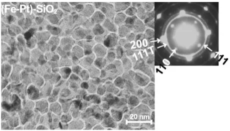
On the other hand, nano-granular type media were obtained for the (Fe–Pt)–SiO2 layer and the (Fe–Pt)-Al2O3. Figure 12 shows the microstructure of the (Fe–Pt)–SiO2layer with coercivity of 0.38 MA/m. The (Fe–Pt)–SiO2 layer exhibited the nano-granular structure with around 10 nm Fe– Pt grains separated by the channels of SiO2 phase. A magnetic domain size was 76 nm by MFM observation, and the pattern showed dotted type.33)This is due to the nano-granular structure with the isolated Fe–Pt grain.
111T
(a)
(b)
200
110
20 nm
Fig. 9 TEM images of Fe–Pt layer prepared by two-step method. Preformed first-layer = 2 nm, second layer = 7.5 nm. (a): plan-view, (b): cross sectional view.
Preparation temperature, Tsub / K
300 400 500 600 700 800 900 1000
Coercivity,
Hc
/ MA
.m
-1
0.0 0.2 0.4 0.6 0.8 1.0
Fe-Pt composite =12 nm
Fe-Pt (Fe-Pt)-MgO
(Fe-Pt)-Al2O3
[image:4.595.54.285.74.258.2](Fe-Pt)-SiO2
Fig. 10 Relationships between preparation temperature and perpendicular coercivity for composite Fe–Pt layer.
[image:4.595.309.545.300.431.2]Fig. 11 TEM image of (Fe–Pt)–MgO layer of double-layered medium.
[image:4.595.312.542.477.608.2]4. Possibilities of Fe–Pt(001) Media
4.1 Recording properties
Recording properties were studied for the above described media. Kerr effect hysteresis loops for the media are shown in Fig. 13. The coercivities of the media were controlled so as to become a similar level by changing sputtering temperature shown in Figs. 8 and 10.
Figure 14 shows density properties of SN ratios for the media, where a unit of the linear recording density is Mega-flux reversal per meter, MFRPM. A single pole type head (Fe–Si–N main pole, Bs¼1:8T, pole thickness = 0.4mm, pole wide = 2mm) for writing34)and a GMR head (shield gap length = 0.13mm, track width = 0.62mm) for reproducing were used. The highest SN ratio was obtained by the pinning type medium with the 2 nm thick preformed layer. On the other hand, the granular type (Fe–Pt)–SiO2 medium exhib-ited the lowest SN ratio in spite of showing the dotted type domains of the smallest size.
The effect of the domain sizes on the SN ratios is
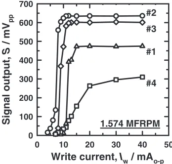
[image:5.595.338.513.74.240.2]summarized in Fig. 15. Except for the (Fe–Pt)–SiO2medium, the SN ratio was improved with reducing the domain size. This is because the media noise is suppressed with reducing the domain size. On the other hand, the lowest SN ratio of the (Fe–Pt)–SiO2 medium is due to a smallest signal output which is caused by an unsaturated recorded state as follows. Saturation recording properties for the media are shown in Fig. 16. The pinning type medium, the (Fe–Pt)–MgO medium and the pure Fe–Pt medium obtained the saturation recorded state, and a steep start-up for each medium corresponded to the hysteresis loop with the steep slope. On the other hand, the (Fe–Pt)–SiO2 medium did not reach the saturation recorded state, thus the large signal output was not realized.
The unsaturated recorded state for the (Fe–Pt)–SiO2 medium is due to the microstructure of the nano-granular type composite film. By the channels of SiO2phase shown in the TEM image, the lateral exchange-coupling was elimi-nated. Then, the perpendicular hysteresis loop exhibited the inclined shape by demagnetizing field, and a saturation field of the loop was over 1 MA/m, as shown in Fig. 13. This saturation field was too large to realize the saturation recording by the applied writing head. In addition, a start-up slope of the saturation curve was smaller, corresponding
Applied Field, H / MA.m-1
-1.0 -0.5 0.0 0.5 1.0
Kerr rotation angle,
θ
k-0.4 -0.3 -0.2 -0.1 0.0 0.1 0.2 0.3 0.4
#2 #1
[image:5.595.339.513.293.459.2]#3 #4
Fig. 13 Polar-Kerr loops for double-layered media. #1: pure Fe–Pt (7.5 nm) medium, #2: pinning type medium (preformed first-layer = 2 nm, second-layer = 7.5 nm), #3: (Fe–Pt)–MgO (12 nm) medium, #4: (Fe–Pt)–SiO2(12 nm) medium.
Linear recording density, f / MFRPM
0 5 10 15 20
SN ratio (dB
pp/rms
)
-10 0 10 20 30 40
#2
#1 #3
#4
Tw= 0.62 µm
Fig. 14 Density properties of SN ratios (0.5–50 MHz). Media are the same as in Fig. 13. Unit of x-axis is Mega-flux reversal per meter, MFRPM.
Domain size, D / nm
0 50 100 150
SN ratio (dB
pp/rms
)
0 10 20 30 40 50
unsaturated
1.574 MFRPM
Tw= 0.62 µm t1st= 2 nm
(Fe-Pt)-MgO (12 nm) STD Fe-Pt (3 nm ~ 7.5 nm)
(Fe-Pt)-SiO2 (12 nm)
Pinning by 2-step (7.5 nm + t1st)
t1st= 1 nm
Fig. 15 Relationship between domain size and SN ratio.
Write current, Iw / mAo-p
0 10 20 30 40 50
Signal output,
S
/ mV
pp
0 100 200 300 400 500 600 700
#4
[image:5.595.81.257.338.508.2] [image:5.595.76.256.588.757.2]1.574 MFRPM #1 #3 #2
to the smaller slope of the hysteresis loop. This is the disadvantage to formation of a sharp transition of the recorded bit in writing process.
4.2 Fe–Pt(001) media design model
From the above results to obtain the higher SN ratio, it was found that two kinds of properties should be considered. One was the smaller domain size for the lower media noise, the other was the saturation recorded state for the higher signal output. The coexistence of both the properties should be needed for the higher SN ratio.
Considering the limitation of a magnetic field generated by a writing head, it will be difficult for the isolated Fe–Pt granular type media to obtain the saturation recorded state. On the other hand, pinning type media of thinner films with large saturation magnetization were reported to have a lager loop slope and a smaller domain size.4) As shown in the above described results, the advantages of the pinning type brought about the saturation recorded state easily and the lower media noise. Accordingly, the pinning type media model is suitable to the design of the Fe–Pt media for the magnetic recording system. Further high SN ratio is expected to be attained by the increase in the density of the pinning sites.
Recently, a heat assisted magnetic recording technology is attracting considerable attention as a future recording technology to realize the saturation recording for the media with a large coercivity.35) In this technology, the heated region should be limited small for the formation of ultra-high density recorded bits. Since the SiO2phase has a low thermal conductivity in the (Fe–Pt)–SiO2film, it will be easy to limit the heated region to the several Fe–Pt nano-grains surround-ed by the SiO2phase. Thus, the composite nano-granular type (Fe–Pt)–SiO2 film is expected to be applied to the heat assisted magnetic recording system.
[image:6.595.315.539.426.526.2]4.3 High density recording for pinning type media A high density recording property was studied in the conventional magnetic recording system by using the narrower shield gap GMR reproducing head (shield gap length = 0.092mm, track width = 0.25mm).
Figure 17 shows density properties of the pinning type Fe– Pt medium with the 2 nm thick preformed layer, compared with a Co–Cr–Nb–Pt granular type medium with a lower media noise property.36) The Fe–Pt medium showed still larger media noise, however, the reproducing resolution,D50,
is very high, whereD50is a linear density for half amplitude of maximum signal output. Thus, the SN ratio at of linear recording density of 19.68 MFRPM is better than that of the Co–Cr–Nb–Pt medium. Accordingly, the Fe–Pt medium is desirable for high density recording.
Figure 18 shows reproduced waveforms for the 0.7874 MFRPM recorded signal. Transition widths for half height of the reproduced waveform,T50, were 22.1 nm for the Fe–Pt medium and 49.5 nm for the Co–Cr–Nb–Pt medium. The very narrow T50 value of the Fe–Pt medium was found to fulfill the condition of the resolution for attaining 310 Tbit/m2.37)
TheT50and alsoD50values are affected by the shield gap length,Gs, of the reproducing head. The dependence of the
T50 on theGs is shown in Fig. 19. The experimental values agreed well with the calculated one that was based on Ref. 38) with the assumption of the ideal step function for magnet-ization transition (a¼0). This suggests that the high reproducing resolution of the Fe–Pt medium is due to a great effect of the thinner recording layer. Furthermore, the thinner recording layer is necessary to achieve even higher resolution in applying future narrower shield gap GMR reproducing heads. In the pinning type Fe–Pt media, only 5 nm thick recording layer with sufficient thermal stability was con-firmed,16)which will bring about a great advantage to a future ultra-high density medium in combination with narrower shield gap GMR reproducing heads.
Linear recording density, f / MFRPM
0 5 10 15 20
Signal output,
S
/ mV
pp
0 500 1000
Media noise (0.5-50 MHz),
N
/ mV
rms
0 100 200
D50
CoCrNbPt Fe-Pt
D50
Linear recording density, f / MFRPM
0 5 10 15 20
SN ratio (dB
pp/rms
)
0 10 20 30 40 50
CoCrNbPt
Fe-Pt
[image:6.595.337.513.588.756.2]Tw= 0.25 µm
Fig. 17 Density properties of (a) signal output and media noise, (b) SN ratio, for Fe–Pt pinning type medium (#2 in Fig. 13) and Co–Cr–Pt–Nb medium.
Fig. 18 Reproduced waveforms for 0.7874 MFRPM recorded signal. Media are the same as in Fig. 17.
Shield gap length, Gs / nm
0 50 100 150 200 250
Transition width,
T50
/ nm
0 50 100 150
Assumption:
πa=0, Flying height = 50 nm
Rec. thick. =100 nm
=50 nm
=10 nm
Calc.
Measured for CoCrNbPt (50 nm)
Fe-Pt (7.5 nm) Measured for
[image:6.595.54.284.646.747.2]5. Conclusions
Two types of nanostructured Fe–Pt perpendicular double-layered media were tailored as high density recording media. A heteroepitaxial layer configuration and a high pressure sputter-deposition method were essential to obtain an ordered fct(001) phase at the temperatures of 573 to 673 K. For a pinning type medium, crystal defects were induced by a two-step deposition method. A granular type medium was obtained by a nano-composite film with the channels of SiO2phase. The highest SN ratio and reproducing resolution were found to be realized by the pinning type medium. An ultra-high resolution is expected to be verified if a narrower shield gap reproducing head would be applied. For future ultra-high density magnetic recording, further increasing the density of pinning sites will be a key technology. On the other hand, the nano-composite granular type medium is expected to be applied to a heat assisted magnetic recording technol-ogy.
Acknowledgments
The author would like to thank Dr. S. Iwasaki, President of Tohoku Institute of Technology, Dr. K. Ouchi and Dr. N. Honda of AIT, for their encouragement and discussions. The author also expresses his thanks to Mr. K. Ise of AIT for providing the SPT head. This work was partially supported by Akita Prefecture Collaboration of Regional Entities for the Advancement of Technological Excellence, JST.
REFERENCES
1) S. Iwasaki: IEEE Trans. Magn.20(1984) 657–662.
2) S. J. Greaves, H. Muraoka, Y. Sugita and Y. Nakamura: IEEE Trans. Magn.35(1999) 3772–3774.
3) T. Suzuki, T. Kiya, N. Honda and K. Ouchi: J. Magn. Magn. Mater.235
(2001) 312–318.
4) T. Suzuki, H. Muraoka, Y. Nakamura and K. Ouchi: IEEE Trans. Magn.39(2003) 691–696.
5) Von L. Graf und A. Kumann: Physik. Zeitschr.XXXVI(1935) 544– 551.
6) O. A. Ivanov, L. V. Solina, V. A. Demshina and L. M. Magat: Phys. Met. Metallog.35(1973) 81–85.
7) B. M. Lairson, M. R. Visokay, R. Sinclair and B. M. Clemens: Appl. Phys. Lett.62(1993) 639–641.
8) A. Cebollada, D. Weller, J. Sticht, G. R. Harp, R. F. C. Farrow, R. F. Marks, R. Savoy and J. C. Scott: Phys. Rev. B50(1994) 3419–3422. 9) M. R. Visokay and R. Sinclair: Appl. Phys. Lett.66(1995) 1692–1694.
Nakajima: J. Magn. Magn. Mater.148(1995) 163–164.
11) M. Watanabe and M. Homma: Jpn. J. Appl. Phys.35(1996) L1264-L1267.
12) Y. Ide, T. Goto, K. Kikuchi, K. Watanabe, J. Onagawa, H. Yoshida and J. M. Cadogan: J. Magn. Magn. Mater.177(1998) 1245–1246. 13) H. Kanazawa, G. Lauhoff and T. Suzuki: J. Appl. Phys.87(2000)
6143–6145.
14) T. Suzuki, N. Honda and K. Ouchi: J. Magn. Soc. Jpn. 21-Supplement-2(1997) 177–180.
15) T. Suzuki, T. Kiya, N. Honda and K. Ouchi: J. Magn. Soc. Jpn.24
(2000) 247–250 (in Japanese).
16) T. Suzuki, T. Kiya, N. Honda and K. Ouchi: IEEE Trans. Magn.36
(2000) 2417–2419.
17) D. W. Hoffman and J. A. Thornton: J. Vac. Sci. Technol.20(1982) 355–358.
18) M. H. Hong, K. Hono and M. Watanabe: J. Appl. Phys.84(1998) 4403–4409.
19) B. Bian, D. E. Laughlin, K. Sato and Y. Hirotsu: IEEE Trans. Magn.36
(2000) 3021–3023.
20) M. Hirabayashi and S. Weissmann: Acta Metall.10(1962) 25–36. 21) G. S. Kandaurova, L. G. Onoprienko and N. I. Sokolovskaya: Phys.
Status Solidi73(1982) 351–360.
22) B. Zhang and W. A. Soffa: IEEE Trans. Magn.26(1990) 1388–1390. 23) T. Suzuki and K. Ouchi: J. Appl. Phys.91(2002) 8079–8081. 24) K. R. Coffey, M. A. Parker and J. K. Howard: IEEE Trans. Magn.31
(1995) 2737–2739.
25) T. Shimatsu, E. G. Keim, T. Bolhuis and J. C. Lodder: J. Magn. Soc. Jpn.21-Supplement-2(1997) 313–316.
26) S. Stavroyiannis, I. Panagiotopoulos, D. Niarchos, J. A. Christodoulides, Y. Zhang and G. C. Hadjipanayis: Appl. Phys. Lett.
73(1998) 3453–3455.
27) M. Yu, Y. Liu, A. Moser, D. Weller and D. J. Sellmyer: Appl. Phys. Lett.75(1999) 3992–3994.
28) N. Li and B. M. Lairson: IEEE Trans. Magn.35(1999) 1077–1081. 29) C. Chen, O. Kitakami, S. Okamoto, Y. Shimada, K. Shibata and M.
Tanaka: IEEE Trans. Magn.35(1999) 3466–3468.
30) B. Bian, D. E. Laughlin, K. Sato and Y. Hirotsu: J. Appl. Phys.87
(2000) 6962–6964.
31) M. Watanabe, T. Masumoto, D. H. Phing and K. Hono: Appl. Phys. Lett.76(2000) 3971–3973.
32) M. L. Yan, H. Zeng, N. Powers and D. J. Sellmyer: J. Appl. Phys.91
(2002) 8471–8473.
33) T. Suzuki and K. Ouchi: IEEE Trans. Magn.37(2001) 1283–1285. 34) K. Ise, K. Yamakawa, K. Ouchi, H. Muraoka, Y. Sugita and Y.
Nakamura: IEEE Trans. Magn.36(2000) 2520–2523. 35) M. H. Kryder: Digest of Joint [NA]PMRC 2003. (2003) pp. 68. 36) J. Ariake, N. Honda, K. Ouchi and S. Iwasaki: IEEE Trans. Magn.36
(2000) 2411–2413.
37) H. Muraoka and Y. Nakamura: Digests of the 25th annual conference on magnetics (2001) pp. 245 (in Japanese).