Thermal Decomposition Behavior of Expandable Pattern Including Blended
Metal or Alloy Powder in Evaporative Pattern Casting Process of Cast Iron
*Takeshi Kobayashi
1and Toru Maruyama
11
Department of Material Science and Engineering, Faculty of Engineering, Kansai University, Suita 564-8680, Japan
Metal or alloy powder capable of exothermic reaction with cast iron melt was blended into expandable polystyrene patterns. The behavior of thermal decomposition of the expandable patterns in evaporative pattern casting of cast iron was investigated. In evaporative pattern casting in which patterns including blended powder of metallic Si, Fe-Si alloy, Fe-Si-Mg alloy, or Fe-Si-Ca alloy were used, the temperature of the melt was higher than that in casting with original non-blended patterns. When the blending ratio was increased, the volume and pressure of decomposition gas during casting process were increased and, on the other hand, the filling rate of the melt was reduced. The use of patterns blended with powder caused no defect and abnormal structure in castings. These results imply that blending of metal or alloy powder into a pattern accelerates thermal decomposition of the pattern.
(Received July 14, 2003; Accepted September 22, 2003)
Keywords: acceleration, alloy powder, cast iron, evaporative pattern casting process, exothermic dissolution, exothermic reaction, expandable pattern, expandable polystyrene
1. Introduction
In evaporative pattern casting process, since the melt fills up the inside of the pattern while thermally decomposing the expandable pattern, the temperature at the top of the melt flow remarkably drops by the endothermic reaction. The filling rate of the melt is restrained because the melt is pushed back toward the gate by thermal decomposition gas. In addition, the heat of the melt is absorbed also by the pattern coating and, as a result, temperature drop of the melt is further accelerated. The temperature drop causes incomplete thermal decomposition of the expandable pattern, the pattern is not gasified and liquefied resin is generated partially. The liquefied resin sometimes causes residual (carbon) defects of castings. To deal with these problems, the behavior of thermal decomposition of expandable polystyrene (herein-after referred to as EPS) patterns in evaporative pattern casting of cast iron was investigated. Some kinds of metal and alloy powder were selected which are capable of exothermic reaction with cast iron melt and melt into the melt. EPS patterns were prepared, in which these kinds of metal or alloy powder were blended. In this study, metal or alloy powder was not added to the original EPS beads at the time of copolymerization but the pre-expansion polystyrene beads before pattern forming were coated with metal or alloy powder and patterns were manufactured using these coated beads. Cast iron melt was cast into these patterns, and the temperature drop at the top of the melt flow, filling rate of the melt inside the patterns, and the volume and pressure of decomposition gas were investigated.
2. Expandable Patterns Including Blended Metal and Alloy Powder
A mold of Al-Zn system alloy made by spray forming was
used.1)The mold (40 mm1145 mm, 182 cm3) was filled
with the pre-expansion beads (expansion ratio of 40 times) of 3.645 g, set in an autoclave, heated and pressurized for 3.5 minutes under 55 kPa. The pre-expansion beads were expanded again, fusion between beads was accelerated and, thus, EPS expanded patterns (apparent density:
0.020 g/cm3) were manufactured. As the kinds of metal
and alloy powder, metallic Si (99.99 mass%), Fe-75 mass%Si alloy, Fe-45 mass%Si-4 mass%Mg alloy, and Fe-60 mass%-Si-30 mass%Ca alloy powder were used. These kinds of
powder had an average particle diameter of about 17mm. The
blending ratios were 1.5 and 3.0 mass%. Precisely weighed metal or alloy powder of 0.0547 or 0.1093 g and pre-expansion EPS beads of 3.645 g were put into an antistatic
polyethylene sack (about2103cm3). The sack was filled
with air, sealed and shaken by dry shaking process to attach the powder on the surface of the pre-expansion beads. Since the pre-expansion beads are charged with static electricity, the powder can be attached satisfactorily without adhesive agent. The beads blended with the powder were expanded in the same way as the above-mentioned non-blended pattern. In this way, expandable patterns including blended metal or alloy powder (hereinafter referred to as powder-blended patterns) were prepared.
3. Experimental Procedure
3.1 Confirmation test for exothermic reaction of metal or alloy powder with cast iron melt
For each of the above-mentioned four kinds of metal and
alloy powder, two end sealed silica tubes ( 4 mm
300 mm) were prepared. Powder sample of 3.00 g was taken out from each kind of metal and alloy powder and colloidal silica of 5.0 mass% was added as bond to each sample. The powder sample was applied to the outer surface of one of the two tubes over a length of 30 mm from the sealed end to make a candy-like silica tube, which was dried then for 24 hours. Another tube was used without any treatment. High purity pig iron, Fe-75 mass% Si alloy, Fe-75 mass% Mn alloy, and electrolytic iron were blended and melted using a 30 kVA
*This Paper was Presented at the 138th Meeting of Japan Foundry
Engineering Society, held in Chiba, on May 12, 2001 2003 The Japan Institute of Metals
high-frequency induction furnace and a#8 graphite crucible so that the chemical composition of the cast iron melt would be C: 3.6 mass%, Si: 2.1 mass%, and Mn: 0.3 mass% and the total weight would be 5 kg. K (JIS standard) thermocouples were inserted into the two silica tubes respectively. The tubes were immersed in the cast iron melt at a temperature of 1500 K with a distance of 40 mm between them and the temperature transition of both thermocouples were checked.
3.2 Casting design and pouring test
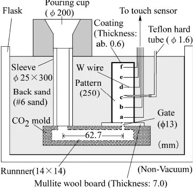
Bottom pouring method was used to assure that cast iron melt flows and fills the mold calmly. Figure 1 shows the
casting design. A gate of13 mm is laid at the bottom of the
pattern. CO2 mold was used for the runner. Two
powder-blended patterns with the size of 40 mm145 mm were
piled up together and connected by winding the periphery with a masking tape to build a single pattern with a total
length of 250 mm. A tungsten wire (0.5 mm) was inserted
as a touch sensor (positiona) 5 mm distant from the pattern
bottom. Tungsten wires as touch sensors were inserted at
additional five positions up tof at intervals of 46 mm from
the positiona. Touch sensors fromatofare connected with
1.5 V battery cells respectively. Diodes were built in the touch sensor circuit to avoid adverse electric current. To measure thermal decomposition gas pressure, a stainless pipe
of1.3 mm was inserted up to the center of the pattern at the
position c 102 mm distant from the pattern bottom. The
stainless pipe was connected to a pressure gauge through a Teflon hard tube and gas pressure was recorded with a recorder. Then the surface of the pattern was coated with
commercial coating material (SiO2 type) in thickness of
about 0.6 mm and subjected to natural seasoning for 48 hours. As shown in Fig. 1, the pattern was set vertically in the flask.
The flask was filled calmly with#6 silica sand and subjected
to triaxial vibration (amplitude: 0.3 mm, frequency: 40 Hz, vibration time: 1 min) to increase the density of back sand.
Using a 30 kVA high-frequency induction furnace and a#8
graphite crucible, cast iron of 6 kg was melted and cast at a temperature of 1623 K. The nominal composition of cast iron was C: 3.6 mass%, Si: 2.1 mass%, and Mn: 0.3 mass%.
Figure 2 shows an example of the change of gas pressure with time and flow distance curve of melt. The stepwise waveform shows flow distance curve. The waveform which rises near 3 seconds in the figure shows gas pressure. This shows that the
pattern decomposed to the position ofcin about 3 seconds.
Therefore, a time difference until melt reaches the position of
cfrom decomposition of the pattern is correspondent to the
thickness of gas reservoir. Table 1 shows some examples of chemical compositions of actual casting specimens. Using a powder-blended pattern having a length of 250 mm, K thermocouples were inserted at positions of 10, 67.5, 125, 182.5, and 240 mm distant from the pattern bottom to measure the temperature of melt. The chemical composition of casting and the casting conditions were the same as those in the case where filling rate of melt and gas pressure were measured as mentioned above.
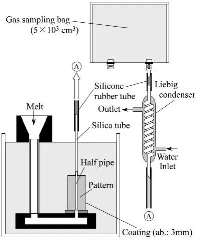
3.3 Measurement of thermal decomposition gas volume
Casting was made using powder-blended patterns
( 40 mm L145 mm). The casting design is shown in
Fig. 3. A hole of 3 mm was bored at the center of the
pattern, a copper half pipe (U-shaped pipe) was inserted into
the hole, and the half pipe was inserted into a silica tube of
4 mm at the top position of the pattern. The half pipe and the silica tube were joined with adhesion bond for mold to assure that decomposition gas does not leak. The silica tube was connected with a Liebig condenser so that decomposition gas
Fig. 1 Schematic illustration of casting design for measuring gas pressure and filling rate of melt.
0 2.0 4.0 6.0 8.0 10.0 0 10 20 30 40 50 a b c d f e Pg
0 2 4 6 8 10 12 14 16 18 0 50 100 150 200 250
(a) Step figure
Voltage, E /V Flow Distance, Df /mm Gas Pressure, Pg /kPa a b c d e f
Time, t/s Electric potential
Gas pressure
(b) Flow distance curve
Pattern: EPS
Casting temp.: 1627K
[image:2.595.319.532.70.326.2]Fig. 2 Change of thermal decomposition gas pressure with passage time (a) and flow distance curve of melt (b).
Table 1 Some examples of chemical composition in eutectic cast iron. (mass%).
[image:2.595.74.262.75.258.2] [image:2.595.305.549.395.453.2]can be led into a gas-sampling bag after cooling. The gas temperature in the bag was 298 K. Gas was then led from the
gas-sampling bag into a syringe (2102cm3), where gas
volume was measured precisely. Further, because the coating thickness of the pattern was approximately 3 mm and the pattern was used after natural seasoning for 48 hours, decomposition gas should hardly penetrate through the coating layer. The chemical composition of casting and the casting conditions were the same as those in foregoing section (3.2).
Still, the reproducibility of the experimental result was obtained by controlling thickness of coating layer and casting temperature precisely.
4. Experimental Results and Discussion
4.1 Confirmation of exothermic reaction of metal or alloy powder with cast iron melt
Figure 4 shows the relation between melt temperature and dipping time in dipping test where a silica tube coated with Fe-Si-Mg alloy powder was dipped in cast iron melt. The data shown in the figure with ‘‘Melt’’ is temperature of the silica tube without coating. The temperature of the silica tube
coated with powder is increased. The temperature risingT
gets to as high as 29.5 K. Figure 5 shows the results of temperature rising obtained in dipping tests where silica tubes coated with metallic Si, Fe-Si, Fe-Si-Ca, and Fe-Si-Mg alloy powder were dipped in cast iron melt. It is found that the temperature is remarkably raised by the reaction of these kinds of powder with melt. When metallic Si is added to iron
melt, exothermic dissolution of metallic Si takes place.2)
When Fe-Si, Fe-Si-Ca, or Fe-Si-Mg alloy is added to cast iron melt, exothermic reaction is caused and these alloys are
melted explosively.3)These kinds of metal and alloy powder
dealt with here produce exothermic reaction with cast iron melt in any case. Therefore, it can be expected that blending
Fig. 3 Schematic illustration of casting design and measurement method of thermal decomposition gas volume.
0
20
40
60
500
1000
1500
Time, t/s
Temperature,
T
/K
Melt
Fe-Si-Mg alloy powder
(3.00g)
∆
T=29.5K
Fig. 4 Relation between melt temperature and dipping time in dipping test of coating layer with Fe-Si-Mg alloy powder.
0 20 40 60 80
Fe-Si Fe-Si-Mg Fe-Ca-Si Metallic Si Metal or Alloy Powder
Temperature Rising,
∆
T
/K
Fig. 5 Comparison of temperature rising by exothermic reaction of cast iron melt with powder between metallic Si and various kinds of alloy powder.
15
20
25
30
35
40
45
Gas Pressure,
P
/kPa
(a)
0
1.0
2.0
3.0
11
12
13
14
Filling Rate,
R
f/mm
.
s
-1
Blending Ratio of Powder,
B
(mass%)
Casting temperature:
1623K
(b)
Si
Fe-Si
Fe-Si-Mg
Fe-Si-Ca
[image:3.595.70.267.72.311.2] [image:3.595.313.543.72.229.2] [image:3.595.325.531.288.421.2] [image:3.595.326.531.486.758.2]these kinds of powder into expandable patterns will accel-erate thermal decomposition of expandable patterns.
Though thermodynamic data of exothermic reaction melting in cast iron melt were not known, the temperature rising in adding 300 K Si to 1873 K melted iron as a reference was calculated. In the calculation, the mass of melt and silicon powder was equal to the dipping test. It was assumed that the system was perfect thermal insulation. As a result of the calculation, the temperature rising is 1.6 K. Though the value is considerably smaller than the experimental result, it
-40
-20
0
20
40
60
80
Original
1.5mass%
3.0mass%
Temperature Difference,
T
/K
∆
Distance from Pattern Bottom,
D
/mm
Casting temperature:1623K
(a) Si
-40
-20
0
20
40
60
80 (b) Fe-Si
3.0mass%
1.5mass%
Original
0
50
100
150
200
250
-40
-20
0
20
40
60
80 (C) Fe-Si-Mg
3.0mass%
1.5mass%
Original
Fig. 7 Relation between distance from expandable pattern bottom and temperature difference (T) in cast iron melt ((a) Si, (b) Fe-Si, (c) Fe-Si-Mg).
0
1.0
2.0
3.0
150
160
170
180
190
200
Blending Ratio of Powder, B(mass%)
Gas Volume,
V
g/ml
.
g
-1
Casting temperature:1623K
Fe-Si
Fe-Si-Mg
Si
Fig. 8 Effects of blending ratio of metal and alloy powder in expandable pattern on the decomposition gas volume.
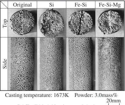
20mm
Casting temperature: 1673K Powder: 3.0mass%
Top
Side
Fe-Si-Mg
Fe-Si
Si
Original
[image:4.595.70.270.68.352.2] [image:4.595.322.532.209.362.2] [image:4.595.84.512.415.777.2]approximates to the experimental value, if it is assumed that the dilution zone between melt and silicon powder occurs locally around the silica tube. For example, the calculated
value becomes about 80 K, when dilution zone is 20 mm
around silica tube which corresponds to melt of 100 g. Therefore, it seems to occur locally the exothermic dissolu-tion.
In case of Fe-Si alloy powder,Tis the smallest. It seems
to be because the melting of this alloy powder needs the time further than other metal and alloy. Actually, except for Fe-Si alloy powder, though they were about 10 seconds in the time until it reached maximum temperature from the reaction initiation, about 60 seconds were needed for Fe-Si alloy powder.
4.2 Effects of blending ratio of metal or alloy powder on filling rate of melt, decomposition gas pressure, and melt temperature
Figure 6 shows the effects of blending ratio of metal or alloy powder on filling rate and decomposition gas pressure. Thermal decomposition gas pressure is increased with the increase in powder blending ratio. The case in which Fe-Si-Mg alloy is blended shows the highest increase. These results imply that blending of metal or alloy powder into expandable patterns accelerates thermal decomposition of patterns, increases generated gas volume, resulting in the increased decomposition gas pressure. It has been reported that when metal oxides are mixed with EPS or brought into contact with EPS and heated, thermal decomposition of EPS is accelerated
by catalytic action.4–8)Therefore, it can be thought that when
metal or alloy powder is blended into EPS patterns, the powder reacts with cast iron melt exothermically and accelerates decomposition of patterns and, in addition, the powder accelerates decomposition of patterns all the more by catalytic action as in the case with metal oxides.
Filling rate of melt is decreased with the increase in blending ratio of powder as seen in Fig. 6. Filling rate is decreased most remarkably when Fe-Si-Mg alloy powder is blended. It is known that filling rate of melt is decreased
when thermal decomposition gas pressure is increases.9)
Therefore, the above-mentioned result implies that thermal decomposition of EPS patterns is accelerated, decomposition gas pressure is increased, and, thus, filling behavior of melt is prevented by decomposition gas pressure. From the result obtained, it was confirmed that blending of metal and alloy powder into EPS patterns accelerates thermal decomposition of EPS patterns.
Figure 7 shows the relation between the distance from the
expandable pattern bottom and temperature difference T.
Temperature difference T means the difference between
the reference temperature and the temperature at various distances from the pattern bottom when the reference temperature is defined as the melt temperature at the position of 10 mm distant from the pattern bottom. Here, the measured temperature in each position is maximum temperature after melt arrival. The temperature difference for the non-blended patterns (Original) is negative and its absolute value increases with the increase in the distance from the pattern bottom. In other words, as the pattern top is approached, melt temperature is decreased. This is supposedly because the melt
loses heat in order to thermally decompose the pattern. On the other hand, the temperature difference at the pattern top for the powder-blended patterns is positive and larger than that at the pattern bottom. Namely, in contrast with the original patterns, the temperature at the pattern top is higher. This implies that the melt reacts exothermically with the metal or alloy powder in the pattern.
If melt temperature is lowered by thermal decomposition
of the pattern, the viscosity of the melt is increased.10)As a
result, misrunning of the melt and carbon defects are caused sometimes.
The temperature rising as exothermic dissolution was calculated as well as describing in the previous section. It is 0.2 K in case with blending ratio of 3.0 mass%. Though the exact evaluation is difficult, because the data on the exothermic dissolution about cast iron melt is unknown, it seems to occur locally the exothermic dissolution in the casting experiment. However, in the result of Fig. 7, because there is temperature rising of about 70 K in the middle point of the melt filling, it is probably an overstatement that this temperature rising is explained only in the exothermic dissolution. Therefore, it is considered to have the catalysis in which metal and alloy powder decreases the endothermic value by the thermal decomposition of EPS pattern.
When cast iron melt was poured into patterns including Fe-Si-Ca alloy powder, a large amount of gas was generated and precise measurement of melt temperature was impossible. This is supposedly because Ca in this alloy powder reacts with water vapor during pattern forming to produce calcium hydroxide, which is thermally decomposed by the melt, resulting in the generation of a large amount of gas. In subsequent experiments, Fe-Si-Ca alloy powder was not used.
4.3 Relation between blending ratio of powder and thermal decomposition gas volume
Figure 8 shows the relation between blending ratio of powder and thermal decomposition gas volume. With the increase in the blending ratio, decomposition gas volume is increased in any metal or alloy powder. As shown in Fig. 7, due to the reaction heat of melt with metal or alloy powder, melt temperature hardly drops as compared with the original pattern. This is supposed to be the reason for the increased decomposition gas volume. The fact shown in Fig. 6 that decomposition gas pressure increases with the increase in the blending ratio of powder also supports the tendency that decomposition gas volume increases with the increase in the blending ratio. It is known that when decomposition temper-ature of EPS patterns increases, lower hydrocarbon such as
methane and acetylene increases.11–13)Though the increased
decomposition gas volume is supposedly caused by the reaction heat of melt with metal or alloy powder as mentioned above, it is also possible that it is caused by catalytic action of the powder.
4.4 Appearance of surface, macrostructure and micro-structure of the casting
the castings can be seen in any powder-blended patterns. In the case of the pattern in which Fe-Si-Mg alloy powder is blended, shrinkage cavities are observed because of high melt temperature. The shape of expandable beads is recognized clearly.
While clear shape of expandable beads is observed on the top surface of the casting made using the original pattern, the shape of expandable beads has collapsed and shrinkage has occurred on the top surface of the castings made using powder-blended patterns. This seems to be a result of occurring from the difference between melt temperature at the tip. The shrinkage cavity does not arise, due to low temperature of melt at the tip, when it was cast in non-blended pattern, and that the casting solidifies from upper part, and that melt is supplied from the lower. On the other hand, melt temperature at the tip rises, when it is cast in powder-blended patterns, and the casting upper part solid-ification slows down compared with that of non-blended pattern. As the result, the melt supply stopped before the macro solidification shrinkage in upper part of the casting, and the shrinkage cavity seemed to arise. Figure 10 shows the relation between the macrostructures on vertical cross sections at the casting top and blending ratio of powder. The macrostructure was observed in the casting top where
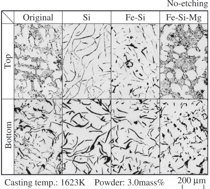
Top
No-etching
Bottom
Casting temp.: 1623K Powder: 3.0mass%
200
µ
m
Fe-Si-Mg
Fe-Si
[image:6.595.305.548.74.323.2]Si
Original
Fig. 11 Graphite structure on cross section of the casting top and bottom.
Original
Si
Fe-Si
Fe-Si-Mg
Top
20
φ
40
(mm)
Cross section
3.0
1.5
Blended ratio, B(mass%)
[image:6.595.82.514.376.765.2]10mm
Etching: 3% Nital
defects could occur easily. In any powder-blended pattern, no gas defect or carbon defect can be observed. It is found that blending ratio of powder hardly acts on the occurrence of defects in castings.
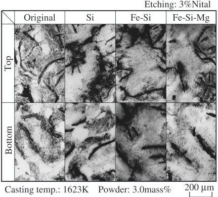
Figure 11 and Figure 12 show graphite structures and matrix structures on cross sections at the casting top and bottom, respectively. As for graphite structures, E- or D-type undercooled graphite is observed at the top of the casting made using the non-blended original pattern. Melt temper-ature at the casting top of the original pattern was low as shown in Fig. 7, which is supposed to have caused under-cooling and crystallization of E- or D-type graphite. Except Fe-Si-Mg alloy powder, all of the graphite structures of castings made using other powder-blended patterns were of A-type graphite. Namely, no inoculating effect by metal or alloy powder was noticed. As for the pattern in which Fe-Si-Mg alloy powder was blended, since the melt at the casting top was heated, undercooling took place. Therefore, D-type graphite is observed. The matrix structures in the case of powder-blended patterns consist of a small amount of ferrite and pearlite. No difference was observed between the matrix structures of casting top and bottom. In the case of the matrix structures of castings made using patterns in which Fe-Si-Mg and Fe-Si alloy powder are blended, a tendency is observed
that the pearlite structure becomes dense to some degree and the amount of ferrite decreases.
By the way, when metal or alloy powder of 3.0 mass% is blended into the pattern and if it is assumed that the powder is included completely in the casting, the calculated concen-tration of powder in the casting is about 83 ppm. However, the actual concentration is thought to be less than this value, if that there is the powder which adheres to the coating layer is assumed.
5. Conclusion
Metal or alloy powder was blended into expandable patterns. The effect of the powder to accelerate thermal decomposition of the patterns and the casting behavior in evaporative pattern casting of cast iron were investigated. The results obtained are as follows.
When metal or alloy powder is blended into EPS patterns, the temperature of melt is raised higher than initial temper-ature and thermal decomposition of patterns is accelerated in evaporative pattern casting. It was confirmed that thermal decomposition gas volume and gas pressure are increased and, as a result, filling rate of melt is decreased. In addition, it was found that the use of powder-blended patterns causes no
Etching: 3%Nital
Top
Bottom
Casting temp.: 1623K Powder: 3.0mass%
200
µ
m
Fe-Si-Mg
Fe-Si
[image:7.595.82.513.76.465.2]Si
Original
casting defect and abnormal structure in castings.
REFERENCES
1) T. Kobayashi, T. Maruyama, M. Kano and M. Hotta: ‘‘Kankyotekiou-gata sokeizai kinozairyou kaihatsu’’, Research Report I, The Institute of Industrial Technology of Kansai University (2001) pp. 120-140. 2) D. M. Stefanescu:Metal Handbook 9th eds. Vol. 15, Casting, (ASM
International, 1988) pp. 62-64.
3) H. H. Cornell: modern casting76/3 (1986) 40-41. 4) K. Suzuki and T. Takahashi: Plastics17/3 (1966) 55. 5) K. Suzuki and T. Takahashi: Plastics16/11 (1965) 52.
6) S. Ide, T. Ogawa, T. Kuroki and T. Ikemura: J. Appl. Polym. Sci.29
(1984) 2561.
7) Y. Uemichi, H. Kanbayashi, T. Kanezuka: Kobunshi Ronbun shu50
(1993) 887.
8) Z. Zhang, T. Hirose, S. Nishio, Y. Morioka, N. Azuma, A. Ueno, H. Ohkita and M. Okada: Ind. Eng. Chem. Res.34(1995) 4514. 9) T. Kobayashi and Y. Kasuya: IMONO64(1992) 794-800. 10) W. Hopf and others: Giesserei Forshung52/3 (2000) 100-111. 11) C. A. Goria, G. Serramoglia and G. Tosi: AFS Trans.94(1986)
589-600.
12) C. E. Bates, J. Griffin and H. Littleton:Expandable Pattern Casting Vol. 1 process Manual, (AFS Inc., 1994) pp. 74-75.