warwick.ac.uk/lib-publications
A Thesis Submitted for the Degree of PhD at the University of Warwick
Permanent WRAP URL:
http://wrap.warwick.ac.uk/108066
Copyright and reuse:
This thesis is made available online and is protected by original copyright.
Please scroll down to view the document itself.
Please refer to the repository record for this item for information to help you to cite it.
Our policy information is available from the repository home page.
IEDDED CODING ALGORITHMS APPLICABLE TO
T IME VARIABLE CHANNELS
By:
Farshid Zolghadr, B.Sc., AMIEE
A thesis presented for the degree of
Doctor of Philosophy in the Department
of Engineering, University of Warwick
THE BRITISH LIBRARY
D O C U M E N T SU PPLY C E N T R E
BRITISH THESES
N O T I C E
T he quality o f this reproduction is heavily dependent upon the quality
of the original thesis submitted for microfilming. Every effort has been
made to ensure the highest quality of reproduction possible.
If pages are missing, contact the university which granted the degree.
Som e pages may have indistinct print, especially if the original pages
w ere poorly produced o r if the university sent us an inferior copy.
Previously copyrighted materials (j°urnal articles, published texts, etc.)
are n ot filmed.
Reproduction o f this thesis, other than as permitted under the United
Kingdom Copyright Designs and Patents A c t 1988, o r under specific
agreement with the copyright holder, is prohibited.
T H IS T H E S IS H A S B E E N M IC R O F IL M E D E X A C T L Y A S R E C E IV E D
T H E B R IT I S H f L IB R A R Y
D O C U M E N T SU PPLY C E N T R E
Boston Spa, W etherby
W e st Yorkshire. LS23 7 B Q
TABLE O F CONTENTS
TITLE PAGE
CONTENTS i
LIST OF TABLES A N D ILLUSTRATIONS V
ACKNOWLEDGEMENTS x
DECLARATIONS xi
ABSTRACT x ^v
CHAPTER 1 : INTRODUCTION 1
CHAPTER 2 : THEORETICAL BACKGROUND 6
2.1 Source Coding (theory) 6
2.1.1 Discrete Sources 6
2.1.2 Huffman Coding 9
2.1.3 Run-Length Codes 10
2.1.4 T-codes: Methods of Code Construction 11
2.2 Channel Models (theory) 17
2.2.1 Discrete Memoryless Channels 17
2.2.2 Channels with Memory 20
2.3 Channel Coding (theory) 22
2.3.1 B l o c k Codes 22
2.3.2 Decoding of Linear Block Codes 24
2.3.3 Convolutional Codes 26
2.3.4 Decoding of Binary Convolutional Codes 30
2.3.5 S o f t Decision Decoding 31
2.4 Modems for Time Variable Channels 34
2.4.1 Modulation Methods 34
2.4.2 Demodulation Methods 36
CHAPTER 3 : REAL TIME CHANNEL EVALUATION 41
3.1 Introduction 41
3.2 Statistical Real Time Channel Evaluation (SRTCE) 44
3.2.1 SRTCE System 44
3.2.2 Use of T-codes in an SRTCE System 50
3.2.3 SRTCE in the P resence of AWGN 53
3.2.4 SRTCE for the Gilbert-Elliot Channel 55
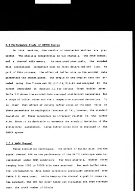
3.3 Performance Study of S R T C E System 58
3.3.1 AWGN Channel 58
3.3.2 The Gilbert-Elliot Channel 61
3.4 Discussions 63
CHAPTER 4 : EMBEDDED BLOCK ENCODING 65
4.1 Introduction 65
4.2 Embedded Array Codes 66
4.2.1 Code Structure 69
4.2.2 Performance Analysis 70
4.2.3 Results 80
4.3 Modified Embedded A rray Code 85
4.3.1 Performance A nalysis 86
4.4 Discussions 88
CHAPTER 5 : EMBEDDED CONVOLUTIONAL ENCODING 90
5.1 Introduction 90
5.2 Embedded Convolutional Encoding 93
5.2.1 The Overall System 94
5.2.2 ARQ Format 99
5.3 Main System Elements in Detail 101
5.3.1 The Encoder 101
5.3.2 The Channel 103
5.3.3 Metric Evaluator 10 4
5.3.4 Soft Decision Decoder 105
5.3.5 Real Time Channel Evaluation 108
System (Error Limiter)
5.4 Performance Study 1 1 3
5.5 Discussions 1i5
CHAPTER 6 : MULTIPLE FREQUENCY SHIFT KEYING MODEM 118
6.1 Introduction 1 1 g
6.2 Overview of Some Common Synchronisation Met h o d s 120
6.3 Principles of the CABS System 123
6.4 Implementation of the CABS Modem 1 3 5
6.4.1 Modulator Design Philosophy 135
6.4.2 Demodulator Design and Implementation 140
6.5 Results of Simulation and On-Line Testing 144
of the Modem
6.5.1 Simulation Results 1 4 5
6.5.2 Modem Operation Verification 146
6.5.3 AWGN Channel Test Results 148
6.5.4 HF Trials Test Results 150
6 . 6 Discussions 1 5 3
CHAPTER 7 : CONCLUSIONS A SUGGESTIONS FOR FURTHER WORK 155
7. 1 Conclusions 1 5 5
7.1.1 Statistical RTCE 155
7.1.2 Embedded Block Encoding Techniques 156
7.1.3 Embedded Convolutional Encoding 156
7.1.4 MFSK Modem Algorithms 157
7.2 Further Work 158
7.2.1 Extensions of Multi-Functional Coding 158
7.2.2 Improvement of the Embedded Encoding 1 59
7.2.3 Embedded Convolutional Code Under 159
CABS Environment
7.2.4 Improvements of the CABS Modem 160
7.2.5 Extensions of the CABS Modem 161
7.2.6 Semi-Orthogonal MFSK Modulation Format 161
REFERENCES 164
SYMBOLS AND ABBREVIATIONS 176
APPENDIX A : ERROR PROBABILITY OF PARTIAL ARRAY CODE 180
APPENDIX B : ERROR PROBABILITY OF EMBEDDED ARRAY CODE 182
APPENDIX C : PERFORMANCE ANALYSIS OF THE OUTER DECODER 185
APPENDIX D : PERFORMANCE ANALYSIS OF (52.36) ARRAY CODE IN 189
AN ARQ SYSTEM
APPENDIX E : MODULATOR PROGRAM LISTING 191
APPENDIX F : DEMODULATOR PROGRAM LISTING 196
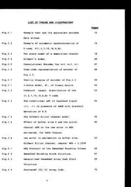
LIST o r TABLES AND ILLUSTRATIONS Tig.2.1 Fig.2.2 Fig.2.3 Fig. 2.4 Fig. 2.5 Fig.2.6 Fig.2.7 Fig.3.1 Fig.3.2 Fig.3.3 Fig.3.4 Fig.3.5 F ig.3.6 F ig.4.1 Fig. 4.2 F ig.4.3 F ig.4.4
Example text and its equivalent encoded 15
data stream.
Example of automatic synchronisation of 16
T-code, S{ 1,3,7,15,10,6,8}.
Two state model of a memoryless channel. 18
Gilbert's model. 20
Convolutional Encoder for v»3, m=2, b = 1 . 27
Tree-code representation of encoder of 28
Tig.2.5.
Trellis diagram of encoder of Fig.2.5 29
2-state model, M 1 , of binary source. 45
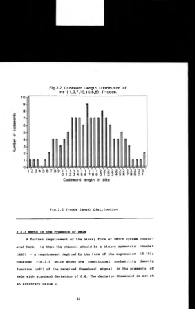
Codeword length distribution of the 53
(1,3,7,15,10,6,8) T-code.
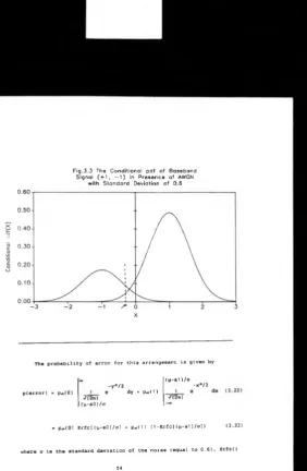
The conditional pdf of baseband signal 54
(♦1, -1) in presence of AWGN with standard
deviation of 0.6.
The Gilbert-Elliot channel model. 56
Effect of buffer size N and the actual 60
channel BER on the rms error in BER
estimated, for AWGN Channel.
rms error in estimation vs buffer size, 62
Gilbert Elliot channel, channel BER = 0.0508.
ARQ Protocol of the Embedded Encoding Scheme. 66
Embedded Encoding Block Structure. 67
Generalised Embedded Array Code Block 69
Structure.
Fig.4.5 Embedded Array Code, Decoder structure. 72
Fig.4.6 Block Diagram of 'Super channel'. 72
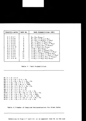
Fig.4.7 Possible Decoding Paths. 74
Fig.4.8 Required Number of Repeat Requests for 75
Decoding a Given Sub-Block.
Fig.4.9 Decoding Paths and Their Probabilities. 76
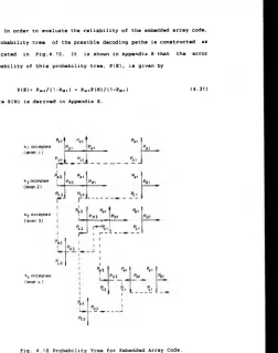
Fig.4.10 Probability Tree for Embedded Array Code. 79
Fig.4.11 (52,12) Embedded Array Code Block Structure. 80
Fig.4.12 Theoretical Throughput of array and Embedded 83
Array Codes under AWGN Channel Conditions.
Fig.4.13 Theoretical Reliabilities of Array and 83
Embedded Array Codes under AWGN Channel
Conditions.
Fig.4.14 Simulated Throughput of Array and Embedded 84
Array Codes under AWGN Channel Conditions.
Fig.4.15 Simulated Reliability of Array and Embedded 84
Array Codes under AWGN Channel Conditions.
Fig.4.16 Modified Embedded Encoding Scheme. 85
Fig.4.17 (64,23) Modified Embedded Array Code Block 86
Structure.
Fig.4.18 Simulated Throughput under AWGN Channel for 87
(52,12) Embedded Code and (64,23) Modified
Embedded Array Code.
Fig.4.19 Simulated reliability under AWGN Channel 87
for (52,12) Embedded Code and (64,23)
Modified Embedded Array Code.
Fig.5.1 ARQ Protocol of the Embedded Convolutional 91
Code.
Fig.5.2 Embedded Convolutional Encoded Block Structure. 91
Fig.5.3 System Block Diagram. 94
Fig.5.4 Convolutional Encoder for 133<«>, 171,., Code. 95
Fig.5.5 Metric Assignment for Soft Decision Data. 99
Fig.5.6 Trellis Diagram for 7<«>, 5,., convolutional 106
code.
Fig.5.7 pdf of the Error Detection Metrics for 110
Channel SNR«2dB, Rate«1/2.
Fig.5.8 pdf of the Error Detection Metrics for 110
Channel SNR=3dB, Rate«1/2.
Fig.5.9 pdf of the Error Detection Metrics for 111
Channel SNR«4dB, Rate-1/2.
Fig.5.10 Mean and Standard Deviation of the Error 111
Detection Metrics vs Channel SNR (dB).
Fig.5.11 Output BER vs Channel S/N (dB) for Code Rate 112
1/2, 2/3 and 3/4 Convolutional Code.
Fig.5.12 Throughput of the Embedded Convolutional 114
and the Comparison Codes.
Fig.5.13 Reliability of the Embedded Convolutional 114
and the Comparison Code.
Fig.6.1 CABS Modulator Block Diagram. 124
Fig.6.2 CABS System Convolutional Encoder and 124
Trellis Diagram.
Fig.6.3 Block Diagram of the Noncoherent Correlator. 125
Fig.6.4 Noncoherent Correlator outputs for Input 127
Tone Sequence 1, 4, 2, 3 and 2.
Fig.6.5a pdf of the Correlator Output based on HypO, 131
T.»1 , E«1, o=0.1 with mean of Z « 1.02.
Fig.6.5b pdf of the Correlator Output based on Hypl, 132
T„= 1, E= 1, o=0.1 with mean of Z = 0.02.
134
Fig.6.6 CABS System Decoding Procedure. 134
Fig.6.7 Frequency Response of a Noncoherent Correlator. 137
Fig.6.8 Transceiver Overall Frequency Response. 138
Fig.6.9 Modulator frequency Response. 139
Fig.6.10 CABS Demodulator Block Diagram. 140
Fig.6.11 The Block Diagram of the Digital Noncoherent 141
Correlator.
Fig.6.12 Diagrammatical Description of VECO and V E C 1 . 142
Fig.6.13 Bit Error Rate of the CABS Modem, 145
Noncoherent MFSK System (uncoded)
and Coded MFSK System vs Eb/N0 .
Fig.6.14 Practical Measurement of the four Correlator 147
Outputs for the Tone Sequence of 1, 4, 2, 3,
2 and 4.
Fig.6.15 Practical Synchronisation Waveform of the CABS 147
Demodulator/Decoder Observed in Real-Time.
Fig.6.16 Block Diagram of the AWGN Test Configuration. 148
Fig.6.17 Low-Pass Filter Frequency Response. 148
Fig.6.18 Practical Measurements of the CABS Modem BER 149
for an AWGN Channel Condition.
Fig.6.19 Cumulative Error-Free Run Distribution for 151
Testl, Overall BER=0.0011, Sample Size*51000.
Fig.6.20 Consecutive Burst Distribution for Testl, 151
Overall BER«0.0011, Sample Size=51000 bits.
Fig.6.21 Cumulative Error-Free Run Distribution for 152
Test2, Overall BER=0.0107, Sample
Size=52000 Bits.
Fig.6.22 Consecutive Burst Distribution for Testl, 152
Overall BER=0.0107, Sample Size*52000 Bits.
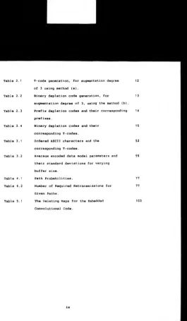
Table 2.1 T-code generation, for augmentation degree 12
of 3 using method (a).
Table 2.2 Binary depletion code generation, for 13
augmentation degree of 3, using the method (b).
Table 2.3 Prefix depletion codes and their corresponding 14
prefixes.
Table 2.4 Binary depletion codes and their 15
corresponding T-codes.
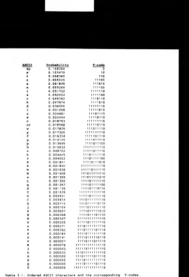
Table 3.1 Ordered ASCII characters and the 52
corresponding T-codes.
Table 3.2 Average encoded data model parameters and 59
their standard deviations for varying
buffer size.
Table 4.1 Path Probabilities. 77
Table 4.2 Number of Required Retransmissions for 77
Given Paths.
Table 5.1 The Deleting Maps for the Embedded 103
Convolutional Code.
[image:13.341.45.310.0.455.2]ACKNOWLEDGMENTS
Z would like to express my sincere gratitude to my supervisor.
Dr. B. Honary, for his guidance, encouragement and valuable comments
throughout this work. I would also like to thank Professor M. Darnell
for his valuable comments during the course of this research.
I am also indebted to my colleagues in the Hull-Warwick Communi
cations Research Group, without whose encouragements, helpful com
ments and friendship I would not have been able to complete this
work.
Finally, I would like to take this opportunity to thank my par
DECLARATIONS
The following is a list of the materials which have either been
published or submitted for publication, during the course of this re
search programme, along with the sections of the thesis to which they
relate. These materials are the direct result of the work carried out
by the author from the of October 1985.
1) Zolghadr, F., Honary, B., Darnell, M . , "Statistical Real Time
Channel Evaluation (SRTCE) techniques using variable length T-codes",
IEE Proc., Com., Speech and Vision, Vol.136, Pt.Z, No.4, pp259-266,
Aug. 1989.
Relevant thesis sections:- 3.1, 3.2, 3.3 and 3.4.
2) Zolghadr, F., "Preliminary Investigation of Embedded Array Encod
ing", Internal Report, Coventry Polytechnic, Jan. 1987
Relevant thesis sections:- 4.1, 4.2, 4.4 and Appendices A to D.
3) Darnell, M., Honary, B., Zolghadr, F.,: "Embedded coding tech
niques: principles and theoretical studies.", IEE Proc. -F, Comm. Ra
dar and Signal Processing, Feb. 1988
Relevant thesis sections:- 4.1, 4.2, 4.4 and Appendices A to D.
4) Darnell, M., Honary, B., Zolghadr, F., "Embedded Array Coding For
HF Channels, Theoretical & Practical Studies", Proc. of IMA C o n f . on
"Cryptography and Coding", Ed. (Beker, H. J.), Oxford Univ. Press,
pp135-152, 1989.
Relevant thesis sections:- 4.3 and 4.4.
5) Zolghadr, F., Honary, B., Darnell, M.,: "Embedded Convolutional
Coding.", Proceedings of the 1ERE, Fifth Int. Conf. on Digital Proc
essing of Signals in Comm., Sept. 88.
Relevant thesis sections:- 5.1, 5.2, 5.3 and 5.4.
6) Zolghadr, F., "Reliable, Interference Resistance, Data Transmis
sion Techniques for Multi-User HF Communications", Progress Report
No.2 to Royal Aerospace Establishment (Farnborough) Contract No.
2119/037, Aug. 1988.
Relevant thesis sections:- 6.1, 6.2, 6.3 and 6.5.
7) Honary, B. Zolghadr, F., Darnell, M., "A Code-Assisted Bit Syn
chronisation (CABS) Scheme", Electronics Letters, Voi. 25, No. 23,
1 9«» jan. 1989.
Relevant thesis sections:- 6.3 and 6.5.
8) Zolghadr, F., "Reliable, Interference Resistance, Data Transmis
sion Techniques for Multi-User HF Communications", Progress Report
No.3 to Royal Aerospace Establishment (Farnborough) Contract No.
2119/037, Jan. 1989.
Relevant thesis sections:- 6.1, 6.3, 6.4, 6.5.
9) Honary, B., Zolghadr, F., Darnell, M., "Convolutional Encoding for
Both Synchronisation and Protection Over HF Channels", IEE Colloquium
on "Adaptive HF Management", London March 1989.
Relevant thesis sections:- 6.1, 6.3, 6.4, 6.5.
10) Zolghadr, F., "Reliable, Interference Resistance, Data Transmis
sion Techniques for Multi-User HF Communications” , Progress Report
No.4 to Royal Aerospace Establishment (Farnborough) Contract No.
2119/037, Apr. 1989.
Relevant thesis sections :-6.1, 6.2, 6.3, 6.4, 6.5, 6.6 and Ap
pendices E and F.
11) Honary, B . , Zolghadr, F., Darnell, M., Maundrell, M . ,
"Multi-Functional MFSK Coding over Poor Narrow-Band HF Channels", IEE
Proc. Part X, Submitted for publication Jun. 1909.
Relevant thesis sections:- 6.1, 6.2, 6.3, 6.4, 6.5, 6.6.
12) Zolghadr, F., "Reliable, Interference Resistance, Data Transmis
sion Techniques for Multi-User HF Communications", Progress Report
No.6 to Royal Aerospace Establishment (Farnborough) Contract No.
2119/037, September 1989.
Relevant thesis section:- 6.3.
13) Zolghadr, F., Honary, B., "Digital Matched Correlator Automatic
Gain Control (Mc-AGC) Scheme Applicable to MFSK Modems", Submitted to
IEE Proc. Part I, Oct. 1989.
Relevant thesis sections:- 6.3 and 7.2.
ABSTRACT
This thesis investigates new design and implementation tech
niques applicable to modern communication systems operating over time
variable channels. Three areas of interest are investigated. These
include, source coding in conjunction w ith real-time channel evalua
tion, channel coding and modem design.
An investigation of source coding methods has led to the devel opment of a new embedded real time channel evaluation, based on sta
tistical techniques. The performance of this technique is examined
using simulation techniques for channels with and without memory.
Existing channel coding schemes applicable to time variable
channels have been examined. This led to the formulation of a new
coding technique, termed embedded encoding. Two implementations of
such codes, embedded array codes and embedded convolutional codes,
were developed. The theoretical and practical performance of these
codes has been investigated.
The final area of investigation has been the development of a 4-tone multi-frequency shift keying modem. In keeping with the inten
tion of totally digital system design, the demodulator has been im
plemented on a single digital signal processing card. The demodula
tion method developed employs an embedded synchronisation technique, termed Code-Assisted Bit Synchronisation.
The demodulator performs symbol synchronisation by utilising the
convolutional code used for the purpose of channel coding. It thus
performs the combined functions of the demodulator, decoder and sym
bol timing recovery, which are normally found as separate sub
systems. In combining these subsystems a more efficient modem has
been developed.
CHAPTER 1
INTRODUCTION
Communication is the transfer of messages from a d a t a source to
a d a t a sink. A message can take many physical forms e.g. sound,
light, electrical, etc. In this thesis only electrical messages are
considered. Electrical messages can be grouped into either analogue
or d i screte formats. With the recent advances in digital computers,
the u s e of discrete messages have become increasingly more wide
spread. This increased demand, has resulted in extensive efforts be
ing concentrated on the development of reliable and efficient com
munication systems.
T h e main attribute of many message streams is the inherent re
dundancy which exists within them. For efficient communication these
messages should contain as little redundancy as possible. The removal
of the message redundancy is referred to as source coding.
T h e transfer of messages involves the utilisation of various
modules, i.e. modulator, demodulator and the communication medium.
The modulator, which is employed at the transmitter, translates the
digital message stream into a suitable format for transmission over
the communication medium. There are many modulation techniques in use
today. Basically, these techniques operate by varying some parameter
of a constant amplitude sinusoidal signal (the carrier), in response
to the message stream.
T h e demodulator, on the other hand, is situated at the receiver
and performs the exact reverse operation to that of the modulator.
The demodulation process involves the detection of the changes intro
duced b y the modulator in the carrier signal and the subsequent map
are numerous methods of signal detection available, the choice being
dictated by cost, complexity and the required performance.
The communication medium, usually referred to as the channel, is
the means by which the message is conveyed to the receiver. In the
context of this thesis, the channel, characterises a radio communica
tion medium comprising, the radio frequency (RF) circuit, antennas
and the ionosphere. In this medium, information is conveyed by the
propagation of electromagnetic waves in space. The characteristics of
the channel are controlled by the choice of the RF frequency, the
property of the medium a n d the antenna. The term "a Time Variable
Channel" describes a communication medium in which the effects of the
channel vary with time.
The reliability and the efficiency of any communication system
depends directly on the choice of the above system modules and the
properties of the medium. The choice of the modulation and the d e
modulation methods have a direct influence on the resilience of the
communication system towards the unwanted effects of the channel.
These unwanted effects a r e the various distortions of the transmitted
message, caused by the channel. These distortions manifest themselves
in many physical forms, e.g. purely additive noise effects, phase and
frequency instabilities, etc. The direct result of these distortions
is the introduction of errors in the message stream delivered to the
recipient of the information.
As a means to combat the effect of the errors caused by the
channel, error control techniques are employed. Generally speaking,
error control coding (channel coding) techniques are implemented by
adding redundant information to the digital message before transmis
sion. In practice, the digital message stream (i.e. the data) is d i
vided into blocks on w h ich a set of parity check calculations are
performed. The result of this operation are the necessary redundant
information digits which are added to each block of data.
A measure of the maximum amount of information that can be
transmitted over a channel, is the channel capacity. The channel ca
pacity is monotonie function of the received signal to noise ratio
(SNR). Clearly, for time variable channels the channel capacity var
ies with time. Shannon has shown [Shannon 1948] that if the transmis
sion rate does not exceed the channel capacity, it is possible to
transmit coded information with an arbitrary small probability of er
ror at the output of the decoder; however the block length must be
allowed to increase without limit.
As a direct consequence of the Shannon's channel capacity
theorem and the variable channel capacity experienced over time
variable channels, enormous amount of effort has been spent on devis
ing techniques for estimating the instantaneous channel status. These
techniques are broadly referred to as Real-Time Channel Evaluation
(R T C E ) techniques. RTCE techniques allow appropriate action to be
taken in response to the information obtained via continuous monitor
ing of the channel state.
This thesis concentrates on the design and implementation of new
algorithms applicable to modern communication systems operating over
time variable channels. The investigation considers three main areas
of interest. These include, source coding in conjunction with RTCE,
channel coding and modem design.
The second chapter of this thesis reviews some of the theoreti
cal background relevant to this thesis. In the first section funda
mentals of information theory are outlined. This is followed by the
description of various forms of source coding techniques. Two of the
channel coding in the context of block and convolutional codes are
reviewed, and the principles of modem design for time variable chan
nels are outlined.
In the third chapter the principle of a new RTCE technique is
presented. This algorithm is an extension of source coding procedures
widely used today. The technique known as statistical RTCE (SRTCE)
[Zolghadr Honary Darnell 1989] is particularly applicable to channels
were the effect of noise is severe. SRTCE is a unique form of RTCE,
which can provide both channel error rate and error distribution
characteristics.
Chapters four and five introduce a new concept in error control
coding termed Embedded coding [Zolghadr 1987, Darnell Honary Zolghadr
1988, Zolghadr Honary Darnell 1988]. Chapter four concentrates on the
theoretical and the simulation study of embedded block codes. Embed
ded block codes employ a combination of forward error correction and
detection in an automatic repeat request (ARQ) environment. In chap
ter five, the concept of embedded coding is extended to convolu
tional codes. In embedded convolutional encoding, punctured convolu
tional codes are used for the purpose of error correction and code
rate variation. Error detection is preformed via a new RTCE technique
which is a by-product of the soft decision decoding of convolutional
c o des.
Chapter six of this thesis is devoted to the development of a
new digital modem algorithm, which combines the functions of the d e
modulator, decoder and the symbol synchronisation subsystems. The de
veloped algorithm is implemented using a digital signal processor
(TMS320c25) to produce a complete modem operating over the High Fre
quency (HF) channel. The modem employs a novel digital processing
1988, Zolghadr 1989a, Honary Zolghadr Darnell 1989, Honary Zolghadr
Darnell Maundrell 1989]. Signal detection is achieved via a set of
noncoherent correlators, while symbol synchronisation and error cor
rection are performed by a soft-decision Viterbi decoder [Viterbi
1971 ].
Finally, chapter seven summarises and discusses the main results
of the research, and suggests ideas for future investigation in this
area.
The Appendices, A through to D, contain the main theoretical
studies of the embedded coding, described in Chapter 4. The last two
appendices present the assembly programs for the CABS modulator and
demodulator. These have been enclosed since the actual implementation
of the algorithm used is in itself a major task and would ease fur
CHAPTER 2
THEORETICAL BACKGROUND
2.1 Source Coding (theory)
In order to improve the efficiency of the communication process,
source coding is applied to remove the redundancy of the message
[Shannon 1948, Abramson 1963, Blahut 1987, Held 1987]. Source coding
is achieved by examining the statistical nature of the symbols in the
source alphabet. Generally speaking, the aim of source coding is to
reduce the average number of symbols required to represent the source
alphabet.
In order to gain a fuller understanding of the concepts of
source coding, it is important to have some basic tools and prin
ciples for describing the source parameters. Consequently, in this
Section the theoretical background of information theory, and the
properties of some simple discrete sources are given. Finally, three
examples of source coding are examined.
2.1.1 Discrete Sources
A discrete source generates a message sequence which consists of
symbols from the source alphabet, i.e.
X i e { X , , X i , X . , --- x 0 ) ( 2 . 1 )
where Xi is a symbol and Q is the size of the alphabet set.
The efficiency of a discrete source is determined by the statis
tical properties of the message sequence, produced by it. Further
g r o u p s :
a) memoryless sources [Abramson 1963 pp13, Gallager 1968 pp40];
b) sources with memory [Sklar 1988 pp599, Kanal Sastry 1978].
A memoryless source, outputs symbols which exhibit no intersym
bol dependency. A good example of such a source is the random number
generators, used for choosing the winning lottery ticket.
If the probability of the source symbols are known, a measure of
information content can be assigned to each symbol:
where I(X».) is the amount of information (in bits) associated with
symbol X»., with the probability of occurrence, p*.
A measure of the average self information of a source, is the
source entropy. The source entropy, H(X), can be viewed as the a v e r
a g e amount of uncertainty associated with the output of a source. For
a memoryless source, the source entropy is defined as:
where E(X) is the expected value of X.
It is clear from (2.3) that a source has maximum entropy if all the
source symbols have equal probability of occurrence. Moreover, for a
memoryless source, the source entropy can bounded by (Blahut, 1987,
pp56-57]:
Z(Xi) ■ -loga p* (2.2)
(2.3)
0 s H (X ) s logaQ- (2.4)
The source symbols probabilities of occurrence, could in theory
known as sources with memory. An example of this type of source is a
source producing a stream of English text, in which there is a strong
intersymbol dependency. The presence of intersymbol dependency se
verely restricts the efficiency of the source. This can be best dem
onstrated by the occurrence of the letter 'q' in a message of the
English text. In this example, the recipient of the message will
(with a high probability) expect the next letter in the message to
be 'u'. Consequently, the transmission of the letter 'u' in this in
stance does not convey very much information.
A measure of information content of sources with memory can be
obtained by generalising equation (2.2). As an example, for a one d i
mensional source (i.e. a source with one symbol dependency), (2.2)
can be written as [Abramson, 1963, p22):
I(X4 |XS ) - -log, P(X*|XS > (2.5)
where X*.|x3 implies the symbol X*. conditional on the symbol X s and
P(x) is the probability of x.
The source entropy in this example can be obtained by extending
equation (2.3), which yields [Abramson, 1963, p35]
e a
H(X) * E {X(Xi|X3 )} « - E E P(X,.,X3 ) .log* P(X*|X3 ) (2.6)
where P(Xi,X3 ) is the probability of symbol X, following the symbol
X 3 .
An examination of equations (2.3) and (2.6) shows that the e n
tropy of a source with memory is lower than that of a memoryless
source with the same alphabet and symbol probability [Sklar, 1988,
p 5 98]. Clearly, a source with maximum entropy conveys maximum
efficient data transfer. In the following Sections, three examples of
source coding techniques are described.
2.1.2 Huffman Coding
Huffman codes are a form of variable-length codes which can
achieve the shortest average code length for a given input alphabet
[Huffman 1952]. In Huffman coding, e ach symbol in the source alphabet
is assigned to a codeword (usually binary). The length of the code
word is chosen such that the information contents of the codeword and
the corresponding symbol are equivalent.
The coding process [Held 1987 pp98-100] is of a tree structure
which is formed by listing the source symbols, along with their prob
abilities, in a descending order of occurrence. These symbols form
the root of the tree with their probabilities labelling the branches.
The two entries with the lowest probability are merged to form a new
node with their composite probability. The pair formed in this manner
is moved up in the list, to ensure the descending probability struc
ture is preserved. The new pair however, is given a higher priority
in the reordering process and is placed above the entries with the
same probability. The above process is repeated until the top of the
tree structure is reached.
The two branches merging into a given node are arbitrary la
belled with 0's and 1's. To find the codeword representing a symbol
X»., the path from the top of the tree is traced to the root of the
tree marked by the symbol X».. T h e binary digits which label the
branches of the path, are then read out as the codeword for symbol
Xi.
A measure of effectiveness of a source coding technique is the
of bits per symbol before and after coding [Sklar 1988 pp657]. When
applying the Huffman coding scheme to memoryless sources, it is pos
sible to achieve high compression ratios. In practice however, since
some degree of conditionality exists between the source symbols, the
level of compression achievable is reduced.
As mentioned in Section 2.2, the intersymbol dependency, reduces
the source entropy. For a m-dimensional source, the effect of inter
symbol dependency can be removed by providing the source with a new
alphabet consisting of all the m-tuples of the original symbols.
The Huffman coding process described above could then be applied to
the m-tuple symbols in the new alphabet. This method of source coding
is known as extended Huffman coding [Abramson 1963 pp86-87, Blahut
1987 pp69-71]. In this manner, higher compression ratio can be o b
tained.
2.1.3 Run-Length Codes
The output of many sources is a sequence of repeated character
sequences, which result in a reduction in the source entropy. In or
d e r to increase the efficiency of the source, the effect of these
long runs should be minimised. An example of this type of sources is
the facsimile machines [Usubuchi et al. 1980]. In facsimile machines
the scanned image is converted into a series of binary digits 0's and
1's (representing black or white levels). The final two-dimensional
array formed in this manner, therefore, consists of many runs of r e
peated bits. The function of source coding is thus to compress the
overall number of bits required to fully describe the scanned image.
Run-length codes are a class of source codes w h ich are highly
suited to this form of messages. These codes operate by making an ap
sub-■titution consists of a "start of compression indicator" followed by
the number of times the character should be repeated and finally the
repeated character itself. In this manner the need for transmission
of all the repeated symbols in the run is eliminated. It is clear
that, this technique can greatly improve the source entropy if long
runs of repeated sym b o l s are present.
2.1.4 T-codes: Met h o d s of Code Construction
T-codes are variable-length codes which exhibit compression r a
tios comparable w i t h Huffman codes. The synthesis of T-codes has been
outlined extensively in [Titchener 1985, Titchener 1986]; and only a
brief review is g i v e n here. There are two basic methods of code g e n
eration:
(a) via the augmentation algorithm,
(b) via the depletion algorithm.
In the augmentation algorithm the following steps are used:
(i) the complete initial character set is listed (set S°), ie
in the binary case the initial character set is (0,1);
(ii) this initial list is repeated;
(iii) a character f rom the first half of the list is allocated as a
prefix to all the elements in the repeated second half of the list.
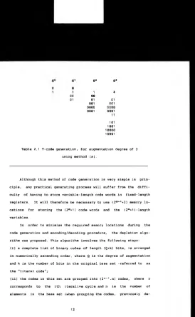
With the repeated application of the above procedure, Q times, an
augmented set of d e g r e e Q is obtained (set S ° ) . This is demonstrated
in Table 2.1 using a binary base set for an augmentation of degree 3.
It should be noted that an augmented binary set of Qth degree always
contains (2°*1) characters.
00 01
s a
s *
1 4
00
01 01
00 1 001
0 0 0 0 0 0 0 0
0 0 0 1 0 0 01
11
101 1001 1 0 0 0 0 1 0 0 0 1
Table 2.1 T-code generation, for augmentation degree of 3
using method (a).
Although this method of code generation is very simple in prin
ciple, any practical generating process will suffer from the diffi
culty of having to store variable-length code words in fixed-length
registers. It will therefore be necessary to use (2°*’,*2) memory lo
cations for storing the (2°+1) c ode words and the (2°+1) -length
variables.
In order to minimise the required memory locations during the
code generation and encoding/decoding procedure, the depletion algo
rithm was proposed. This algorithm involves the following steps:
(i) a complete list of binary codes of length (Q*k) bits, is arranged
in numerically ascending order, where Q is the degree of augmentation
and k is the number of bits in the original base set -referred to as
the "literal code";
(ii) the codes in this set are grouped into (2*r-,.n) codes, where r
corresponds to the rth iterative cycle and n is the number of
[image:30.339.32.306.9.453.2]pleted entries are counted as if still present);
(iii) the set is depleted by a single deletion at an arbitrary, but
corresponding, position in the first and each subsequent alternate
group; the deleted code in the first group is referred to as a
"prefix-depletion code".
The steps (ii) & (iii) are repeated for r»1,2 . .Q, the result
being a set of (2°(n-1 )»1 ] binary depletion code words. Table 2.2
shows the process for a third-order depletion code with a single bit
binary literal code; here Q*3, k»1 and n«2. These c ode words can be
directly translated to the augmented code words using t h e algorithm
detailed below.
s S(0) S(0,1) S{0,1,2}
0000 - _
-0001 0004 -
-0010 0010 0040
-0011 0011 0011 0011
0400 - -
-0101 0101 0101 0101
0110 0110 0110 0110
0111 0111 0111 0111
4000 - -
-1001 4004 -
-1010 1010 1010 1010
1011 1011 1011 1011
4400 - -
-1101 1101 1101 1101
1110 1110 1110 1110
1111 1111 1111 1111
Table 2.2 Binary depletion code generation, for augmentation
degree of 3, using the method (b).
(a) The prefix-depletion codes are labelled depending o n their as
sociation with the iterative cycle, i.e. the first prefix-depletion
code corresponds to the first iterative cycle, etc.
(b) The prefix-depletion code words are examined individually; the
first k bits corresponding to the literal code are left unchanged;
the next Q bits following the literal code are referred to as the
"prefix-selection code". In the process of translation of the
prefix-depletion codes to prefixes, these bits will be replaced by
the previous variable-length prefixes which, along with the literal
code, will form the prefix. Each bit in the prefix-selection code
points to a specific prefix. If the bit is equal to one, the corre
sponding prefix is included and, if the bit is equal to zero, it is
not. It should be noted that, for each new prefix, only the previ
ously determined prefixes are required.
(c) Once all the prefixes have been determined, the translation of
the binary depletion codes into augmented variable-length T-codes can
be carried out. This process is very similar to step (b) above. The
binary depletion code words are examined individually and the first k
bits (the literal code) are left unchanged. The remaining Q bits (the
prefix selection code) are examined, starting with the bit immedi
ately following the literal code. If this following bit is equal to
1, the first prefix (found in the previous step above) is included:
otherwise it is not. This process is repeated for the remaining bits
(and their corresponding prefixes). Tables 2.3 and 2.4 show the p r e
fix generation and the T-code generation processes respectively for
the example of Table 2.2, where S(i,..,j) correspond to the depletion
code set with prefix depletion codes i,..,j.
Prefix depletion codes Prefixes
0 0 0 0 0
0001 1
0010
00
Table 2.3 Prefix depletion codes and their corresponding
Binary depletion codes T-codes
0011 01
0101 11
0110 100
0111 101
1010 0000
1011 0001
1101 0011
1110 00100
1111 00101
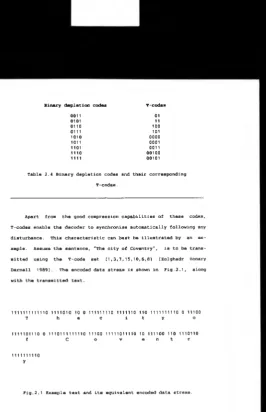
Table 2.4 Binary depletion codes and their corresponding
T-codes.
Apart from the good compression capabilities of these codes,
T-codes enable the decoder to synchronise automatically following any
disturbance. This characteristic can best be illustrated by an ex
ample. Assume the sentence, "The city of Coventry", is to be trans
mitted using the T-code set {1,3,7,15,10,6,8} [Zolghadr Honary
Darnell 1989]. The encoded data stream is shown in Fig.2.1, along
with the transmitted text.
11111111111101111010 1001111111101111110 110 1111111110011100
T h e c i t y o
111110111001110111111110 1110011111011110 10111100 1101110110
f C o v e n t r
1111111110
y
Fig.2.1 Example text and its equivalent encoded data stream.
[image:33.339.38.305.14.427.2]The received data stream is shown in Fig.2.2, where a single
digit error has corrupted the third bit in the second transmitted
symbol -as indicated by the symbol Although this error causes
a loss in synchronisation, the decoder resumes synchronisation after
three symbols and, in fact, only one symbol is actually lost.
1 1 1 1 1 1 1 1 1 1 1 1 0 1 1 010 10 100 1 1 1 1 1 1 1 1 0 1 1 1 1 1 1 0 11 0 1 1 1 1 1 1 1 1 1 00 1 1 1 0 0
T / t e e /e c i t y o
Loss of sync.
1 1 1 1 1 0 1 1 1 0 0 1 1 1 0 1 1 1 1 1 1 1 1 0 11 1 0 0 1 1 1 1 1 0 1 1 1 1 0 10 111 1 00 110 1110110
f C o v e n t r
1111111110
y
Fig.2.2 Example of automatic synchronisation of T code, 3(1,3,7,15,10,6,8).
2.2 Channel Models (theory)
The communication channel causes many forms of degradation of
the transmitted signal, ie distortion, noise and interference. These
effects are complex probabilistic processes, thus it is difficult, if
not impossible, to predict the behaviour of these distortions. The
combined effect of these degradations leads to the corruption of the
transmitted signal, which in turn results in errors at the receiver.
One of the main aims of any communication system is to reduce
the effect of these errors, by utilising reliable communication proc
esses. The design of these schemes, however, relies on the availabil
ity of some knowledge of the channel. Consequently, it is highly de
sirable to have some method of analysing the structure of the error
generating mechanism of channels.
The error generating process of a digital communication channel
can be viewed as a discrete-time stochastic process [Kanal Sastry
1978]. The output of the process is a sequence of error patterns
which are assumed to be statistically independent of the transmitted
data sequence.
Broadly speaking, channels can be characterised into two main
categories :
a) memoryless channels;
b) channels with memory.
Although real channels are a mixture of the above, generally, one
dominates over the other. In the following two Sections these two
classes are discussed.
2.2.1 Discrete Memoryless Channels
A discrete memoryless channel (DMC) is characterised by a dis
condi-tional probabilities which govern the mapping of the channel input
and output sequences. Furthermore, each output symbol of the channel
depends only on the corresponding input.
For a binary DMC the input and output symbols of the channel are
binary. The error patterns formed by the channel can b e represented
as a binary pattern, which are added to the channel input symbols un
der G F (2), where GF(X) is the Galois field with x elements. The main
characteristic of the memoryless channels is that the error mechanism
effects each channel input symbol independently. Moreover, the occur
rence of errors is not dependent on the previous errors. In order to
characterise this type of channels, a two state Markov process can be
used (see Fig.2.3).
Fig.2.3 Two state model of a memoryless channel.
T h e model is composed of two states. So and S , . A t each time in
terval, the model makes a transition from state Z„_, to state Z„,
where n is the time reference. The actual transitions are governed by
the state transition probabilities. The output of the model, Qn , is
formed b y mapping the current state of the model, Z„, to a discrete
output alphabet. For a binary DMC, the following mapping could be
z „ > s<
(2.7) Q~ ■ 0
Z„ - S, Qn ■ 1
where Q„ ■ 1 is a channel error event.
The error generation process of Fig.2.3 is completely described
by the following model parameter [Zolghadr Honary Darnell 1989]:
P(Z„ - Si) - p (2.8)
where P(x) is the probability of occurrence of the event, x.
It is evident that the probability of error for this channel is
given by equation (2.8). Examples of actual channels which can be
closely approximated by this model, include those which are pre
dominately disturbed by Gaussian noise.
The capacity of a channel, C, is given as [see Kanal Sastry
1978]
C - 1 - H„ bits/symbol (2.9)
where H0 is the average conditional entropy of a typical error se
quence of the channel. For a DMC with error rate, p, Ha is the un
conditional entropy and is g i ven as [Kanal Sastry 1978 , (see also
equation (2.3))]
H a (D M C ) « -p.loga p - (1-p).loga (1-p) (2.10)
As discussed in Section 2.1, the basic property of entropy is that it
increases as the memory of the process decreases. Consequently, for a
DMC with bit error rate (BER), p, the channel capacity is lower than
2.2.2 Channels with Memory
For a channel with memory, the occurrence of an error increases
the probability of a further error event. In this manner bursts of
errors occur which are separated by relatively error free intervals.
An example of such channels is the High Frequency (HF) skywave chan
nel .
A simple representation of channels w ith memory is the Gilbert
model [Gilbert 1960], (see Fig.2.4).
Fig.2.4 Gilbert's model
This model is very similar in structure to the model of a DMC
(Fig.2.3). However, this model is now fully described by the follow
ing two parameters [Zolghadr Honary Darnell 1989, Kanal Sastry 1978]:
P(Z„ - So|Zn- i - S , ) - q
(2.11)
P(Z„ - S , |z „ _ , - So) - P
(2.12)
P(Z„ -
P(Z„
-It is clear that for the model
(2.11>*(2.14) and (2.12)8(2.13)
S , ) ■ p / ( p + q ) (2.13)
So) - q / ( p * q ) (2.14)
to be memory less the equation pairs
must be equivalent (ie (p+q) must be
The Gilbert model, like the DMC model, consists of a "good state", So
and a "bad state" S, . No errors are produced in the good state; in
the bad state bursts of errors are generated. The output of the
model, 0,», is formed by mapping the current state of the model, Z„,
to a discrete output alphabet. The mapping process is however,
probabilistic in which the generation of errors in the bad state is
governed by the parameter ,h, ie :
■ So Qn - 0 (2.15)
zn - Si
— > Qn * 1
Qn - 0
probability h
probability (1-h)
(2.16)
where Qn - 1 is a channel error event.
The BER for this channel, P(Q„ » 1), can be evaluated from equations
(2.13)4(2.16)
P(Q„ = 1) = h.p/(p+q) (2.17)
It is clear (see equation 2.9 and 2.6) that the capacity of the
Gilbert channel is higher than that of the DMC. This increase in c a
pacity, which is the characteristic of all channels with memory, is
2.3 Channel Coding (theory)
In this section, the error control techniques used for removing
the channel errors are introduced. Shannon has shown that [Shannon
1948] it is theoretically possible to communicate with very low p rob
abilities of error, even in the presence of noise. However, the p rac
tical achievement of this statement has proved rather difficult.
Shannon's theorem implies that, if a source with entropy, H, is
transmitting data over a channel with capacity C, the BER approaches
zero as long as H s C. In principle, channel coding is concerned
with the controlled addition of redundant data or parity check digits
into the transmitted digits in an attempt to satisfy this condition.
The effectiveness of a coding scheme is measured by how closely
it matches the entropy of the coded data, to the channel capacity
available. Two m ain classes of error control codes are briefly d e
scribed here:
a) block codes;
b) convolutional codes;
2.3.1 Block Codes
Block codes are a class of error control codes, which consist of
a closed set of codewords, where each codeword is of length n with k
information digits (if linear). Block codes can be divided into two
main groups, linear and nonlinear. Linear block codes, form a
sub-space of the vector space V„ of all n-tuples, over a finite field
GF(q), where q is a power of a prime number (q«2 for the binary case)
[Peterson Weldon 1972]. Nonlinear block codes, on the other hand are
generated by means of some nonlinear operators (e.g. n a n d gates
etc.). In this dissertation only linear codes are discussed.
re-dundant digits to every, k, input data digits. In this manner, a
code with block length, n (n = k + c), consists of a set of 21* code
words. The set formed in this way is referred to as a code book. A
code is said to be systematic if the k data digits appear explicitly
in the codeword. A measure of the added redundancy of a code is the
code rate, R, where R*k/n.
Linear codes can be characterised by a generator matrix, G. The
generator matrix is formed by placing k basis vectors as rows of the
k x n matrix. Basis vectors are a set k linearly independent vectors
which span an n-dimensional vector space. For a given code, all the
codewords can be generated by taking all the 2 " linear combinations
of the basis vectors.
The generator matrix is normally used in the Standard Echelon
(SE) form, defined by the linear combination of rows or by rows
interchange [Peterson Weldon 1972]. The SE form of the generator ma
trix has the following structure:
[G] - [I : g] (2.18)
where I is the k x k identity matrix and g is a k x (n-k) matrix. For
systematic codes, the encoding procedure can be viewed as
[X] - [K][G] (2.19)
where [X] is the resulting 1 x n code vector and [K] is the 1 x k
data vector.
One of the important properties of linear block codes is that
the addition (under appropriate GF) of two codewords results in a
valid codeword. This implies that if a code is used for error detec
tion, in order to detect the presence of errors, the error pattern
erty sets the maximum number of errors that an error detection code
can tolerate.
In general, the error control capability of a code is determined
by the Hamming distance of the code. For a linear block code the Ham
ming distance, d, is defined as the smallest non-zero weight of a
codeword in the code.
The error control capability of a code is directly determined by
the Hamming distance of the code. The error correction capability of
the code is given by
t s [ d- 1 j (2.2 0)
where t is the error correction capability of the code (in digits)
and x j implies the integer part of x;
and the number of errors, e, the code can detect is given by
e s d - 1 (2.21)
2.3.2 Decoding of Linear Block Codes
Most of the decoding methods are based on the calculation of the
syndrome vector [MacWilliams Sloane 1977, Michelson Levesque 1985
pp63-69]. The evaluation of the syndrome vector relies on the avail
ability of the parity check matrix. This matrix has dimensions
(n-k)xn, with the property that when multiplied by a valid codeword
vector, [X], gives:
[X] [H]* - [0] (2.22)
where (H]T is the transpose of [H] and [0] is the 1x(n-k) null vec
tor.
The set of all possible codewords is called the null space of
the matrix which has the code book as its null space. In other words,
a multiplication of a codeword with the transpose of the parity check
matrix yields an all zero vector. This property of the [H] matrix is
important for decoding block codes.
Stating equation (2.22) in a different way, it implies that a
1 x n vector [C] is a codeword if and only if
[C] [ H r - [0] (2.23)
Now, if [C] is the received version of a transmitted codeword [X],
and the vector [E] represents the "error" vector, then
[C] - [X] ♦ [E] (2.24)
where the addition is performed under GF[2].
The decoding process would then involve the evaluation of equation
(2.23). The result of this operation is referred to as the syndrome
vector [S], where [S] is given by
[S] - [C] [H]* - ([X] ♦ [EJ) [HJ* (2.25)
[S] = [X] [H]* ♦ [E] [HI* (2.26)
and combining equations (2.23) and (2.26) gives
[S] - [E] [ H r (2.27)
where, again all the operations are performed under GF[2].
From equation (2.27) it is evident that the actual value of the
syndrome vector is only dependent on the error vector. This informa
tion is used as the sole means by which error detection is performed
by a decoder. Once the syndrome vector has been evaluated, its value
would indicate the validity of the received codeword. If [S] = [0],
it is assumed that no errors have occurred. On the other hand a
For error correction, however, the actual value of the non-zero
syndrome is used to find the error vector which has corrupted the
transmitted codeword. It is evident that a unique syndrome exists for
every correctable error pattern. The set of all vectors (corrupted
codewords) having the same syndrome is called a coset of the group of
codewords [Berlekamp 1968]. Furthermore, the number of codewords in a
code, is equal to the number of corrupted codewords in any coset.
In each coset, a word having the minimum weight is chosen as the
coset leader [MacWilliams Sloane 1977]. The coset leader is thus the
most likely error pattern to have corrupted the codewords (provided
the channel is symmetric). In this manner, each syndrome is associ
ated with a particular coset leader. A received corrupted codeword is
decoded by computing the syndrome and finding the coset leader corre
sponding to the syndrome. Finally, the actual decoded codeword is
formed by subtracting (addition in GF(2)) the coset leader from the
received word. This is equivalent to finding the codeword nearest in
distance to the received word.
2.3.3 Convolutional Codes
Convolutional codes [Elias 1955] are a class of error control
codes in which information digits are transmitted as a continuous se
quence with no block structure. In these coding scheme, the redundant
digits check for errors over several consecutive digits. These codes
are also referred to as tree codes since the code bits can be repre
sented as a tree whose branches correspond to the coded segments. As
with block codes, convolutional codes may be used for correcting ran
dom or bursty errors.
Unlike block codes, convolutional codes have check digits which
length of the code. A convolutional encoder may be described as a
linear-state machine consisting of a v-stage shift register and m
linear algebraic function generators [Lin Costello 1983 pp288-290].
The input data, which is usually, though not necessarily, binary, is
shifted along the register, b bits at a time. An example with v-3,
m=2, b=1 is shown in Fig.2.5.
The encoder of Fig.2.5 can also be represented as a tree diagram
of Fig.2.6. In this format, if the first input bit is a zero, the
code symbols are those shown on the first upper branch, while if it
is a one, the output code symbols are those shown in the first lower
branch. This process is continued with every input bit, however the
process moves to the next level.
O U T P U T
From Fig.2.6 it also becomes clear that after the first three
branches the structure becomes repetitive. The reason for this is ob
vious from examination of the encoder. The encoder being a finite
state machine, has a memory of two bits; it is therefore evident that
w i t h the fourth bit entering the shift register, the effect of the
first bit is completely removed. Consequently, the data sequences,
10000.... and 00000... generate the same code symbols after the third
branch.
is the trellis diagram, shown in rig.2.7, where the branches due to
an input zero are printed in bold. The trellis structure of convolu
tional codes stems directly from the repetitive nature of the tree
diagram. Trellis diagrams facilitates the implementation of maximum
likelihood decoding of convolutional codes.
Fig.2.7 Trellis diagram of encoder of Fig.2.5
The error control capabilities of convolutional codes are meas
u red in a similar way to that of block codes. As mentioned in Sec
t ion 2.3.1, Hamming distance directly controls the error correction
capability of a code. T h e determination of the Hamming distance of
convolutional codes is however a difficult task, since the code no
longer posses a finite block. The Hamming distance of a convolutional
c ode can be determined by evaluating the Hamming distance between
all the possible paths through the trellis and the all zeros path.
distance of the code is then the minimum Hamming distance value ob
tained via the search process. The error correction capability of the
code is then given by equation (2.20). As a n example, the Hamming
distance of the code represented in Fig.2.7, is five, thus the code
can correct double digit errors. In the n ext Section the decoding
process of binary convolutional codes is discussed.
2.3.4 Decoding of Binary Convolutional Codes
As discussed in Section 2.2.1, on a symmetric channel, errors
which transform a channel code digit 0 to 1 o r 1 to 0 are assumed to
occur independently from digit to digit w ith probability p. If all
code sequences are equally likely, the function of the decoder can be
described as finding the most probable transmitted sequence based on
the received sequence. The criterion used is, broadly, based on two
techniques, hard decision and soft decision. In any event, the decod
ing process involves searching amongst all the possible paths through
the trellis and choosing a path which satisfies the decoding crite
rion.
In this manner, for every m received b its (ie the received code
symbol), the decoder assigns a decoding metric to a single section of
the trellis diagram. This trellis section w h i c h corresponds to b data
bits, is appended to the end of the trellis diagram. The assigned de
coding metric, is the decoding criterion measure of the received code
symbol, with respect to all the branches of the trellis section. L
such trellises are stored in the decoder buffer, where L is referred
to as the search length of the decoder and is usually set to be five
times the constraint length of the code, v (Viterbi 1967]. The d e
coder then searches through these, L, trellis sections to find a path
In hard decision decoding, the assigned metric is based o n the
Hamming distance. In other words, the received code symbol is com
pared with the m bits labelling the branches (ie the branch symbols)
of the trellis section. The decoding process is then based on choos
ing a code sequence which differs from the received sequence in the
least number of digits [Viterbi 1971]. This is principally b a sed on
three m ain methods: Viterbi algorithm [Viterbi 1967], sequential d e
coding [Reiffen 1962] and threshold decoding [Massey 1963].
The Viterbi algorithm is based on a complete search of all the
possible paths in the trellis. This algorithm results in the minimum
error probability, however, it is evident that as the constraint
length grows the decoding complexity grows exponentially. The sequen
tial decoding method is based on a limited search algorithm. Here,
the distance growth along a given path is monitored; if the growth
exceeds a predetermined value a new path is considered. Although this
scheme suffers from a higher probability of error and decoder storage
overflows, the decoding complexity is somewhat reduced. The threshold
decoding technique is based on the majority of all the parity check
equations (or a suitable sum or combination of them) related to a
particular information digit failing. The check sum may be generated
from the syndrome (H matrix).
2.3.5 Soft Decision Decoding
In the binary case of H.D decoding, the decoder is presented
with two distinct outputs resulting from a single threshold at the
demodulator. This form of decoding however, neglects the additional
information which could be made available by the demodulation proc
ess. This additional information can be used to improve the decoding
decoder [Thiede 1972] to adaptively adjust the demodulator threshold
levels.
A decoding process which is based on the above criterion is re
ferred to as soft decision (S.D) decoding [Chase 1972]. S.D decoding
is a type of probabilistic decoding [Balser Silverman 1954, 1955],
the simplest form of which is erasure or null-zone detection [Bloom
et al 1957]. The received signal is quantised to three symbols: 1, 0
and null, where null represents a signal element close to the H.D
threshold and therefore of doubtful value. In this manner the decoder
has a prior knowledge of the digits which are likely to be in error,
and can decode accordingly. Null-zone detection can be extended to
double-null-zone detection with an improvement in performance
[Cahn 1969]. Generally speaking, optimum decoding is obtained when
the number of threshold levels tends to infinity. Tor the binary case
however, 16 levels is thought to be adequate [Honary 1981 pp60-61] to
obtain near optimum performance.
S.D decoding can be viewed as the assignment of metrics to the
received coded digits, based on some likelihood function. That is to
say, the assigned metrics are based on the probability of the re
ceived digit conditioned on all the possible code symbols having been
transmitted. The function of the decoder is therefore to maximise the
overall likelihood function for the codeword.
As an example, consider a binary PSK signal system operating
over an additive white Gaussian Noise (AWGN) channel, w i t h a trans
mitted symbol energy of E s , and a one sided noise spectral density
N 0 . Let y 3 be the jfct* code digit of the received codeword; and x 3*
be the j*” digit of codeword k, in the codebook. The conditional