ISSN Online: 2151-4844 ISSN Print: 2151-481X
10.4236/sgre.2018.91001 Jan. 16, 2018 1 Smart Grid and Renewable Energy
Experimental Study of the Cloud Influence on
PV Grid Connected System
Yassir Idris Abdalla Osman
1,2,3, Jinping Li
1,2,3*, Xiaofei Zhen
1,2,3, Airong Yang
1,2,31Western China Energy & Environment Research Center, Lanzhou University of Technology, Lanzhou, China 2Gansu Key Laboratory of Complementary Energy System of Biomass and Solar Energy, Lanzhou, China
3China Northwestern Collaborative Innovation Center of Key Technology for Northwest Low Carbon Urbanization, Lanzhou, China
Abstract
In recent years, PV panels witnessed a vigorous gross, as their performance and the leverage of large-scale industrial production steadily decreased costs. Factors such as solar irradiance, insolation, mismatch of modules/arrays cha-racteristic, aging, partial shading situation have a major effect on the har-vested power. Evidence suggests that partial shading situation is the most critical factor and causes a significant reduction in PV system output. In this paper, a method based on two degrees of freedom, namely upper and lower was proposed in order to address the partial shading losses that due to cloud movement. Moreover, an extensive simulation of voltage, current indicators, bypassed modules, fault string, and DC output power was presented to ana-lyze the PV system. The validation of experimental data analysis was carried out on two different days with different amounts of solar irradiance in Minqin County, Gansu Province, China. The results indicated that the power losses were 18.989 W and 127.629 W according to the minimum and the maximum irradiations (1.88 MW/m2) and (2.104 MW/m2) respectively. By considering
the minimum irradiance, the upper and the lower degrees of freedom of the losses were 22.17 W/d, and 15.8 W/d respectively. On the other hand, by con-sidering the maximum irradiance, the upper and the lower degrees of freedom were 130.49 W/d, 125.78 W/d respectively.
Keywords
Photovoltaic Systems, Partial Shading, Current and Voltage Indicators, Degree of Freedom
1. Introduction
Recently, there was a large volume of published studies describing Photovoltaic How to cite this paper: Osman, Y.I.A., Li,
J.P., Zhen, X.F. and Yang, A.R. (2018) Ex-perimental Study of the Cloud Influence on PV Grid Connected System. Smart Grid and Renewable Energy, 9, 1-15.
https://doi.org/10.4236/sgre.2018.91001
Received: November 27, 2017 Accepted: January 13, 2018 Published: January 16, 2018
Copyright © 2018 by authors and Scientific Research Publishing Inc. This work is licensed under the Creative Commons Attribution International License (CC BY 4.0).
10.4236/sgre.2018.91001 2 Smart Grid and Renewable Energy
(PV) array as an essential renewable energy source, obviously, due to the signifi-cant penetration of PV sources in electricity generation [1][2]. It was generally considered that partial shading (PS) may seriously affect the characteristic curve of the PV arrays [3][4][5]. The presence of bypassing diodes provides an alter-nate path for the current, thus the amount of cell’s current of the module is greatly different under PS conditions. Therefore, the PV characteristic curve shows multiple maximum points.
In order to overcome PS effects, a number of techniques have been consi-dered, such as the connection of bypass diodes in anti-parallel to PV cells/ modules. In case, reverse bias occurs to any solar cell/module, this module is bypassed and the full current passes through the bypass diode and thus avoids module damage. Clearly, the integration of bypass diodes into photovoltaic ar-rays is economically costly. Furthermore, extra losses are detected across these diodes under PS conditions. These losses have a major effect in case of low-vol- tage applications. Commonly, the non-linearity of PV characteristic and bypass diodes together are causing a significant issue under PS condition, mainly, the existence of multiple maxima. In order to overcome this issue, a considerable amount of literature has been published on finding GMPP out of all local MPP
[6][7][8]. These publications concentrate on track speed, number and types of sensors required, accuracy, cost, hardware requirements, complexity, etc. On the other hand, techniques based on micro-converters are adopted to deal with PS losses [9], other approaches utilize adaptive reconfiguration for connecting PV modules [10]-[15], AC modules [16][17][18], recovery of energy [19]. The ma-jor disadvantage of these approaches is the higher cost since, each module works at its MPP. A technique based on sudoku puzzle pattern, magic square pattern, and futoshiki puzzle pattern is adopted for reposition of modules which are re-ported in [20] [21] [22] [23]. Mainly, these techniques depend on the shadow pattern to locate the modules in the optimal position in order to minimize the losses. However, these approaches are commonly associated with square PV ar-rays; moreover, the line losses are increased as a result of increasing the length of interconnections. Generally, mismatch losses are a direct result of moving cloud shadows. Moreover, factors such as electrical configuration, PV array shape, and geographic orientation are also influenced mismatch losses [24]. The approach of determining the time window of shadows based on measured data was pro-vided in [25], where an average of around 13 m/s was found as a variant of the shadow’s speed.
Although there are many reports in the literature on the PV performance and output power, most are restricted to overpassing cloud shadows and their effects, irradiance characteristics and mathematical modeling of irradiance as in [26]
[27][28].
10.4236/sgre.2018.91001 3 Smart Grid and Renewable Energy
different amounts of irradiance were analyzed. Voltage and current indicators in addition to mathematical model presented in [29] are considered to detect the faults of PV. An extensive simulation of voltage and current indicators, bypassed modules, fault string, and DC output power was presented. Furthermore, two degrees of freedom are considered, namely upper and lower limit to address the shadow movement over the PV surface. Clearly, the most critical stage of using DOF method, emphasized that the amount of the losses has been revealed based on the measured irradiance of the two different winter days. The DC power losses (upper and lower limit), Average power generation, percentage of genera-tion reducgenera-tion, system consumpgenera-tion [30], and percentage reduction of system consumption is calculated. However, the analyzation provided in this paper based directly on measured data associated with a specific location, the outcomes are not regionally bounded.
2. Methodology
Fault Detection Parameters
In order to detect faults in PV arrays and realize full automatic supervision indi-cators for current and voltage are considered and denoted as NRc and NRv
respectively [29].
m c
sc
I NR
I
= (1)
m v
oc
V NR
V
= (2)
m
I and Vm are the current and voltage of MPP, these parameters can be
calculated at the inverter input.
oc
V and Isc denote the open circuit voltage and short circuit current
re-spectively, these values are related to the inverter and describe the status of irra-diance and temperature in real time. In the light of this, it is necessary for the inverter to have the advantage of monitoring. Within the same context, under normal operation condition Vmo and Imo are the voltage and current of the
PV array at the maximum power point. Furthermore, in the absence of fault the expected values of NRc and NRv are:
mo co
sc
I NR
I
= (3)
mo vo
oc
V NR
V
= (4)
In order to detect the open circuit and short circuit the thresholds for current and voltage TNRcfs and TNRvbm.
Respectively must be defined as follows:
1.02
cfs co
TNR = αNR (5)
1.02
vbm vo
10.4236/sgre.2018.91001 4 Smart Grid and Renewable Energy
where α and
β
denote the relationship between the ratio of current in case of one fault string and fault-free operation, and the ratio between the voltage ra-tion in the case of one PV module was bypassed and fault-free operara-tion respec-tively provided by Equations (7) and (8). Further, in order to avoid detection of the false fault the constant in the Equations (5) and (6) must be included, this constant represent an offset of a 2% respect the expected value of the current in-dicator NRco.1 1 cfs
co p
NR
NR N
α = = − (7)
1 1 vbm
vo s
NR
NR N
β = = − (8)
When the PV array was totally damaged the corresponding voltage and cur-rent for open circuits or short circuit indicators mostly remain under its thre-shold.
Partial shading of PV arrays inevitably reduced the amount of the power out-put [20][31][32]. However, partial shading was characterized by dynamic evo-lution of the cloud, in addition to natural obstacle [24][33].
According to the number of shaded PV modules and the amount of shadow the total output current is reduced. On the other hand, the number of activated bypass diodes in the PV module affected directly the overall output voltage [34]. Monitoring process for current and voltage degradation can be achieved simul-taneously or separately according to the shadow pattern and PV array align-ment. Furthermore, the appearance of these effects is instantaneous due to the irradiance dynamic behavior except in case the PV module totally impaired. Accordingly, current and voltage are particularly useful in this context. Degrada-tion in output voltage is given by:
1
mo m v
mo vo
V V NR
V
V NR
−
∆ = −
(9)
Assuming Ns is a number of PV modules in serious, PV modules bypassed
numbers, BPmod, due to shadow influence are calculated by:
s
BPmod= ∆VN (10)
The variation of degradation in the current output ∆I is given by:
1
mo m c
mo co
I I NR
I
I NR
−
∆ = −
(11)
In case the PV array are connected in parallel, the losses in output current are expressed in term of the number of equivalent faulty strings in open circuit EFs
as:
s p
EF = ∆IN (12)
10.4236/sgre.2018.91001 5 Smart Grid and Renewable Energy
The number of bypassing modules and the equivalent number of faulty strings can be calculated using Equations (10) and (12) respectively in the presence of partial shadow. From Equations (9) and (11), the losses due the shadowing effect in the DC power are given by:
losses 1
c v
co vo
NR NR
P
NR NR
= −
(13)
Estimation of the principal parameters associated with the equations play a major role in the accuracy of this method particularly Isc, Vov, Imo, Vmo, Im,
and Vm.
The ability of the inverter to track the maximum power point affects the as-sessments of Vm and Im. It should be mentioned that the values of NRco,
vo
NR , TNRcfs and TNRvbm are completely independent of MPP real values. In
case the inverter stuck at local maxima, parameters such as NRc and NRv are
lower than the real values of MPP. Clearly, the algorithm will be capable of de-tecting the amount of power losses, which is the difference between the actual MPP and MPP local value.
3. Degree of Freedom
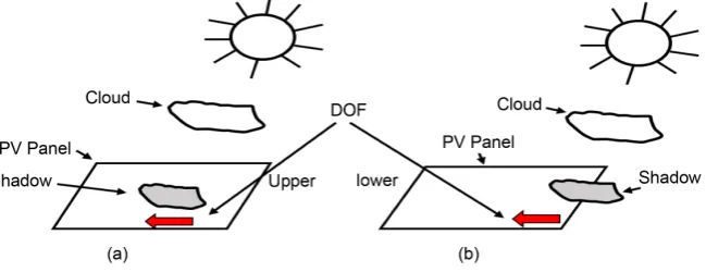
The movement of the shadow over the PV surface is addressed in Figure 1, con-sidering the degree of freedom technique (upper and lower limit) to define the shadow movement (red arrows). Figure 1(a) describes the upper limit case, where the shadow edges are located over the PV surface, on the other hand,
Figure 1(b) shows the lower limit case, where a part of the shadow is situated
over the PV surface. Based on the degree of freedom technique, the output of the system was analyzed and the results were presented.
4. Experiment Setup
[image:5.595.214.539.583.708.2]Partial shading grid connecting PV system phenomenon was analyzed consi-dering the evolution of current and voltage indicators. The PV system was a part of a project designed and tested in a single building in a MinQing China [30]. This experiment was conducted during the winter season, where two different days with different amount of irradiance were considered in order to study the
10.4236/sgre.2018.91001 6 Smart Grid and Renewable Energy
behavior of PV system, in addition to the influence of cloud on the amount of the harvested power. A concept known as the degree of freedom considered de-scribing the dynamic of shadow on the PV panel surface. The experiment out-comes indicate the effectiveness of the proposed method in all situations.
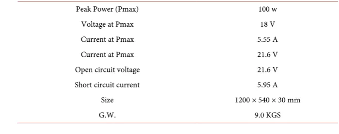
There are a number of instruments are utilized here for monitoring purpose includes two pyranometers (Kipp & Zonen CM 11) to measure irradiance of the panels (daily accuracy of this pyranometer is ±2% and it meets the requirements for this experiment), An Agilent Hp34970A for data acquisition. The configura-tion of the modules is 10 panels 5 parallel-connected strings of 2 series. The complete monitoring system details can be found in [30]. Table 1 presents the parameters of the PV considered in this experiment.
4.1. High Irradiance PV System
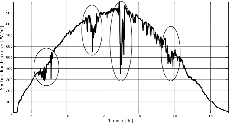
The irradiance pattern is shown Figure 2 where the highlight reveals the inter-vals of shadowing detect by the sensors. Physically the solar cells of the module under PS is bypassed thus the overall active cells is reduced.
The corresponding measured DC output of the PV panels as shown in Figure 3. The irradiance reduction can be seen clearly around 09:00 and 10:00, between 11:00 and 12:00 Also, a considerable reduction noticed around 16:00 moreover, around 13:00 a short disturbance in the grid occurs which leads to a complete inverter shutdown.
It should be mentioned here the influence of these shadows on the output power was well observed on clear days. The voltage indicators evolution is dis-played in Figure 4, where the shadow influences the PV arrays around 09:00, between 11:00 and 12:00 and between 03:00 and 04:20 is more significant. What stands out in this figure is that, during the pre-mentioned interval indicators such as NRv seems under the voltage threshold TNRvbm.
However, reduction in DC output power of the PV arrays around 09:00 it is not because of bypassing PV modules as presented in Figure 4, in which a regu-lar voltage evolution is shown by the indicators. The indicator is clearly ex-plained the inverter disconnection.
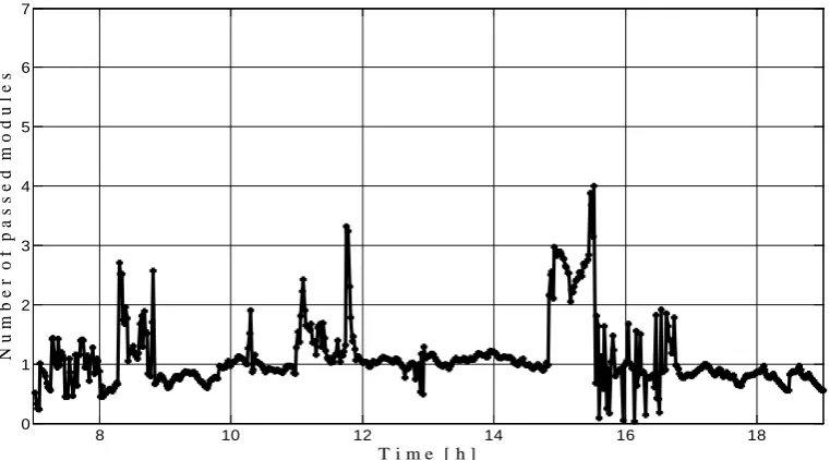
[image:6.595.189.539.592.730.2]The number of bypassing modules is depicted in Figure 5, and their activation
Table 1. Photovoltaic power system configuration.
Peak Power (Pmax) 100 w
Voltage at Pmax 18 V
Current at Pmax 5.55 A
Current at Pmax 21.6 V
Open circuit voltage 21.6 V Short circuit current 5.95 A
Size 1200 × 540 × 30 mm
10.4236/sgre.2018.91001 7 Smart Grid and Renewable Energy Figure 2. Shaded solar radiation pattern March 18, 2015.
Figure 3. Reduction in DC output power due to shade on PV, and inverter disconnection.
is due to shadow phenomenon. The total number of connected modules is Ns =
10. Figure 5 also significantly reveals the shadowy influence at 11:30 that cause
activation of bypassing diode in 2 modules while at noon 4 PV modules are by-passed. Figure 6 shows the zero value of the inverter current input due to the is-landing prevention followed by a normal voltage build up. What stands out in
Figure 6 is that the influence of shadowing phenomenon in the reduction of PV
arrays output current. Particularly at morning, before midday, and at noon is obvious. Figure 6 also clearly determines the interval where the inverter discon-nection occurs, during this interval, the inverter output current is zero and the number of faulty strings is EFs = 2 at the time of fault presence as shown in
Fig-ure 7. The disconnection of the inverter can be translated as a safety measure in
8 10 12 14 16 18
0 100 200 300 400 500 600 700 800 900
S
o
l a
r
R
a
d
i a
t i o
n
[
W
/m
2 ]
T i m e [ h ]
8 10 12 14 16 18
0 100 200 300 400 500 600 700 800 900
T i m e [ h ]
P
( W
10.4236/sgre.2018.91001 8 Smart Grid and Renewable Energy Figure 4. Evolution of voltage at PV output, threshold, and the expected value of the inverter, in normal operation of the PV system.
Figure 5. Number of bypassing PV modules, due to the shadowing of the PV array.
order to avoid islanding. Before the midday the degradation of the current oc-curs because of shadow and hence the equivalent fault EFs is up to 0.47. As a re-sult, the current of the strings is reduced by 25% of expectation.
Further, a reduction of current is detected at 09:00, also between 11:00 to 12:00, and at 03:00. Nevertheless, the amount of power reduction is higher in the morning than in the afternoon.
4.2. Low Irradiance PV System
The irradiance associated to one day of December is presented in Figure 8,
8 10 12 14 16 18
0.55 0.6 0.65 0.7 0.75 0.8 0.85 0.9
T i m e [ h ]
V
o
l t a
g
e
R
a
t i o
N R v T N R v b m N R v o
8 10 12 14 16 18
0 1 2 3 4 5 6 7
N
u m
b e
r
o f
p a
s
s
e
d m
o d u l
e
s
[image:8.595.156.537.343.554.2]10.4236/sgre.2018.91001 9 Smart Grid and Renewable Energy Figure 6. Evolution of current, threshold and inverter output.
Figure 7. Number of equivalent faulty strings.
where a reduction of irradiance is detected around 09:00 Accordingly a reduc-tion in the output power of the PV arrays is observed at the same time interval, this is depicted in Figure 9.
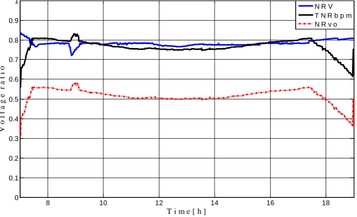
Looking at Figure 10, it is apparent that the shadow of the PV arrays has a very low effect on the evolution of the voltage indicators. Shadowing effects are detected at 09:00, which directly reduces the output power. However, this effect was not significant, due to presence of bypassing modules in the strings. Figure 11 emphasize the fact that the number of bypassing modules has never exceeded one.
By contrast, as seen in Figure 12 a reduction in the current is detected, be-cause of partial shading at 09:00. The output power is reduced according to the current low levels at the same time intervals. Finally, what is appealing about
Figure 13 is that the reduction of the output current at 18:20 was not significant.
8 10 12 14 16 18
0 0.1 0.2 0.3 0.4 0.5 0.6 0.7 0.8 0.9 1
T i m e [ h ]
C
u
r
r
e
n
t R
a
t i o
N R c T N R c f s N R c o
8 10 12 14 16 18
0 0.2 0.4 0.6 0.8 1 1.2 1.4 1.6 1.8 2
F
a u l
t
y
s
t
r
i n g s
10.4236/sgre.2018.91001 10 Smart Grid and Renewable Energy Figure 8. Shaded solar radiation pattern December 31, 2015.
Figure 9. DC output power.
5. Results and Discussions
Table 2 and Table 3 show the system losses based on two degrees of freedom. In
these calculations the average values per day for each parameter is considered. In order to define the upper limit of DOF +3W is added to the average parameter, on the other hand, −3W is subtracted from the average parameter to define the lower limit of DOF.
The most interesting aspects of these two tables are the average generated power is 2.468 kW/d and 2.47 kW/d according to the upper and lower limit of DOF case of low irradiance respectively. On the other hand, when considering
8 10 12 14 16 18
100 200 300 400 500 600 700 800
T i m e [ h ]
S
o
l
a
r
i
r
r
a d
i
a
n
c
e
[
W
/
m
2]
8 10 12 14 16 18
100 200 300 400 500 600 700 800
T i m e [ h ]
P
[ W
10.4236/sgre.2018.91001 11 Smart Grid and Renewable Energy Figure 10. Evolution of voltage indicators.
Figure 11. Number of bypassing modules.
high irradiance case, the average generated power is 2.359 kW/d and 2.364 kW/d associated with the upper and lower limit of DOF respectively. The key aspects of the two days under consideration are firstly, March 18, 2015 has significant irradiance over December 31, 2015. Secondly, December 31, 2015 experience lower losses than March 18, 2015. Thirdly, March 18 2015 is heavily clouded in contrast to December 31, 2015. As a result of a PS event (low irradiance) the av-erage generated power is reduced by 0.88% and 0.64% case of upper and lower limit of DOF respectively. Within the same context, in case of high irradiance the average generated power is reduced by 5.53% and 5.32% with respect to upper
8 10 12 14 16 18
0 0.1 0.2 0.3 0.4 0.5 0.6 0.7 0.8 0.9 1
T i m e [ h ]
V
o
l t a
g
e
r
a
t i o
N R V T N R b p m N R v o
6 8 10 12 14 16 18
0.3 0.35 0.4 0.45 0.5 0.55 0.6 0.65
T i m e [ h ]
B
y
p a s
s
e d M
o d u l
10.4236/sgre.2018.91001 12 Smart Grid and Renewable Energy Figure 12. Evolution of current indicators, threshold and inverter output.
Figure 13. Number of faulty strings.
and lower limit of DOF respectively. The data presented in Table 2 and Table 3
indicates that the system consumption of power is reduced by 0.713% and 0.53% in low irradiance case of upper and lower limit of DOF respectively. On the oth-er hand, in case of high irradiance 4.55% and 4.38% is reported as a reduction of system consumption.
6. Conclusion
In this paper, the PV array system under partial shading caused by moving cloud was investigated. A method based in two degrees of freedom is considered. Moreover, the system was characterized in terms of losses and performances. Simulation and outdoor measurements are conducted in order to validate the
8 10 12 14 16 18
0 0.1 0.2 0.3 0.4 0.5 0.6 0.7 0.8 0.9 1
T i m e [ h ]
C
u r
r
e n t
R
a t
i
o
N R c T N R c f s N R c o
8 9 10 11 12 13 14 15 16 17 18
0.3 0.4 0.5 0.6 0.7 0.8 0.9 1
T i m e [ h ]
n u m
b e
r
o f
f
a
u l
t
y s
t
r
i
10.4236/sgre.2018.91001 13 Smart Grid and Renewable Energy Table 2. Power loss calculation case of low irradiance.
Power losses W Solar irradiance MW/m2 System parameters Values/d
18.989 1.88
Losses upper limit 22.17 W Average generation 2.468 kW Reduction percentage 0.88%
System consumption 2.978 kW Consumption reduction 0.713%
Losses lower limit 15.8 W Average generation 2.47 kW Reduction percentage 0.64%
System consumption 2.98 kW Consumption reduction 0.53%
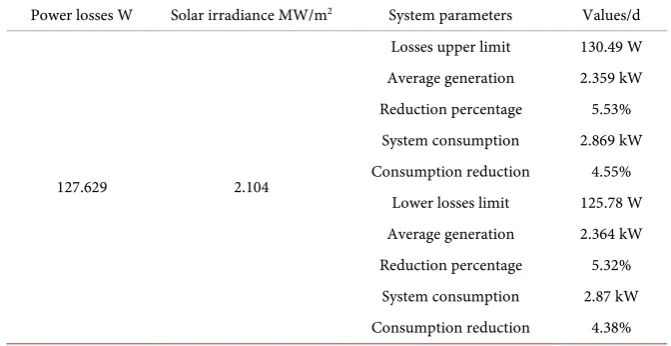
Table 3. Power loss calculation case of high irradiance.
Power losses W Solar irradiance MW/m2 System parameters Values/d
127.629 2.104
Losses upper limit 130.49 W Average generation 2.359 kW Reduction percentage 5.53%
System consumption 2.869 kW Consumption reduction 4.55%
Lower losses limit 125.78 W Average generation 2.364 kW Reduction percentage 5.32%
System consumption 2.87 kW Consumption reduction 4.38%
proposed method. The major advantages of this method are computational effi-ciency, accuracy, simplicity, and the generic formulation. Based on these advan-tages, this method is suitable for fast loss calculation in shaded PV arrays.
References
[1] Mahela, O.P. and Shaik, A.G. (2017) Comprehensive Overview of Grid Interfaced Solar Photovoltaic Systems. Renewable and Sustainable Energy Reviews, 68, 316- 332. https://doi.org/10.1016/j.rser.2016.09.096
[2] Cabrera-Tobar, A., et al. (2016) Review of Advanced Grid Requirements for the In-tegration of Large Scale Photovoltaic Power Plants in the Transmission System. Re-newable and Sustainable Energy Reviews, 62, 971-987.
https://doi.org/10.1016/j.rser.2016.05.044
[3] Seyedmahmoudian, M., et al. (2016) State of the Art Artificial Intelligence-Based MPPT Techniques for Mitigating Partial Shading Effects on PV Systems—A Re-view. Renewable and Sustainable Energy Reviews, 64, 435-455.
https://doi.org/10.1016/j.rser.2016.06.053
[image:13.595.204.540.295.468.2]10.4236/sgre.2018.91001 14 Smart Grid and Renewable Energy https://doi.org/10.1016/j.solener.2017.01.032
[5] Ahmad, R., et al. (2017) An Analytical Approach to Study Partial Shading Effects on PV Array Supported by Literature. Renewable and Sustainable Energy Reviews, 74, 721-732. https://doi.org/10.1016/j.rser.2017.02.078
[6] Roy Chowdhury, S. and Saha, H. (2010) Maximum Power Point Tracking of Par-tially Shaded Solar Photovoltaic Arrays. Solar Energy Materials and Solar Cells, 94, 1441-1447. https://doi.org/10.1016/j.solmat.2010.04.011
[7] Syafaruddin, E.K. and Hiyama, T. (2009) Artificial Neural Network-Polar Coordi-nated Fuzzy Controller Based Maximum Power Point Tracking Control under Par-tially Shaded Conditions. IET Renewable Power Generation, 3, 239.
https://doi.org/10.1049/iet-rpg:20080065
[8] Dhimish, M., et al. (2017) Seven Indicators Variations for Multiple PV Array Confi- gurations under Partial Shading and Faulty PV Conditions. Renewable Energy, 113, 438-460. https://doi.org/10.1016/j.renene.2017.06.014
[9] Lee, J.-P., et al. (2008) A Novel Topology for Photovoltaic DC/DC Full-Bridge Con- verter with Flat Efficiency under Wide PV Module Voltage and Load Range. IEEE Transactions on Industrial Electronics, 55, 2655-2663.
https://doi.org/10.1109/TIE.2008.924165
[10] Balato, M., Costanzo, L. and Vitelli, M. (2016) Reconfiguration of PV Modules: A Tool to Get the Best Compromise between Maximization of the Extracted Power and Minimization of Localized Heating Phenomena. Solar Energy, 138, 105-118. https://doi.org/10.1016/j.solener.2016.09.011
[11] Balato, M., Costanzo, L. and Vitelli, M. (2015) Series—Parallel PV Array Re-Con- figuration: Maximization of the Extraction of Energy and Much More. Applied Energy, 159, 145-160. https://doi.org/10.1016/j.apenergy.2015.08.073
[12] La Manna, D., et al. (2014) Reconfigurable Electrical Interconnection Strategies for Photovoltaic Arrays: A Review. Renewable and Sustainable Energy Reviews, 33, 412-426. https://doi.org/10.1016/j.rser.2014.01.070
[13] Pareek, S. and Dahiya, R. (2016) Enhanced Power Generation of Partial Shaded Photovoltaic Fields by Forecasting the Interconnection of Modules. Energy, 95, 561- 572. https://doi.org/10.1016/j.energy.2015.12.036
[14] Pareek, S. and Dahiya, R. (2016) Series—Connected Shaded Modules to Address Partial Shading Conditions in SPV Systems. AIP Conference Proceedings, 1715, 020020. https://doi.org/10.1063/1.4942702
[15] Vicente, P.D.S., Pimenta, T.C. and Ribeiro, E.R. (2015) Photovoltaic Array Recon-figuration Strategy for Maximization of Energy Production. International Journal of Photoenergy, 2015, 1-11.
[16] Elanchezhian, P. and Chinnaiyan, V.K. (2017) Modeling and Simulation of High- Efficiency Interleaved Flyback Micro-Inverter for Photovoltaic Applications. Mate-rials Today: Proceedings, 4, 10417-10421.
https://doi.org/10.1016/j.matpr.2017.06.391
[17] Kim, H., et al. (2010) A High Efficiency Photovoltaic Module Integrated Converter with the Asymmetrical Half-Bridge Flyback Converter. Solar Energy, 84, 1376-1381.
https://doi.org/10.1016/j.solener.2010.04.019
[18] Hasan, R. and Mekhilef, S. (2017) Highly Efficient Flyback Microinverter for Grid- Connected Rooftop PV System. Solar Energy, 146, 511-522.
https://doi.org/10.1016/j.solener.2017.03.015
Transac-10.4236/sgre.2018.91001 15 Smart Grid and Renewable Energy
tions on Power Electronics, 29, 6458-6471.
https://doi.org/10.1109/TPEL.2014.2302007
[20] Horoufiany, M. and Ghandehari, R. (2017) Optimization of the Sudoku Based Re-configuration Technique for PV Arrays Power Enhancement under Mutual Shading Conditions. Solar Energy.
[21] Pareek, S., Chaturvedi, N. and Dahiya, R. (2017) Optimal Interconnections to Ad-dress Partial Shading Losses in Solar Photovoltaic Arrays. Solar Energy, 155, 537-
551.https://doi.org/10.1016/j.solener.2017.06.060
[22] Sahu, H.S., Nayak, S.K. and Mishra, S. (2016) Maximizing the Power Generation of a Partially Shaded PV Array. IEEE Journal of Emerging and Selected Topics in Power Electronics, 4, 626-637.https://doi.org/10.1109/JESTPE.2015.2498282 [23] Yadav, A.S., et al. (2017) Performance Enhancement of Partially Shaded PV Array
using Novel Shade Dispersion Effect on Magic-Square Puzzle Configuration. Solar Energy, 144, 780-797.https://doi.org/10.1016/j.solener.2017.01.011
[24] Lappalainen, K. and Valkealahti, S. (2017) Effects of PV Array Layout, Electrical Configuration and Geographic Orientation on Mismatch Losses Caused by Moving Clouds. Solar Energy, 144, 548-555.https://doi.org/10.1016/j.solener.2017.01.066 [25] Lappalainen, K. and Valkealahti, S. (2016) Analysis of Shading Periods Caused by
Moving Clouds. Solar Energy, 135, 188-196.
https://doi.org/10.1016/j.solener.2016.05.050
[26] Belhachat, F. and Larbes, C. (2015) Modeling, Analysis and Comparison of Solar Photovoltaic Array Configurations under Partial Shading Conditions. Solar Energy, 120, 399-418.https://doi.org/10.1016/j.solener.2015.07.039
[27] Psarros, G.N., Batzelis, E.I. and Papathanassiou, S.A. (2015) Partial Shading Analy-sis of Multistring PV Arrays and Derivation of Simplified MPP Expressions. IEEE Transactions on Sustainable Energy, 6, 499-508.
https://doi.org/10.1109/TSTE.2015.2389715
[28] Bosch, J.L., Zheng, Y. and Kleissl, J. (2013) Deriving Cloud Velocity from an Array of Solar Radiation Measurements. Solar Energy, 87, 196-203.
https://doi.org/10.1016/j.solener.2012.10.020
[29] Silvestre, S., et al. (2015) Analysis of Current and Voltage Indicators in Grid Con-nected PV (Photovoltaic) Systems Working in Faulty and Partial Shading Condi-tions. Energy, 86, 42-50.https://doi.org/10.1016/j.energy.2015.03.123
[30] Feng, R., et al. (2016) Performance of a Novel Household Solar Heating Thermos-tatic Biogas System. Applied Thermal Engineering, 96, 519-526.
https://doi.org/10.1016/j.applthermaleng.2015.12.003
[31] Belhachat, F. and Larbes, C. (2017) Global Maximum Power Point Tracking Based on ANFIS Approach for PV Array Configurations under Partial Shading Condi-tions. Renewable and Sustainable Energy Reviews, 77, 875-889.
https://doi.org/10.1016/j.rser.2017.02.056
[32] Belhaouas, N., et al. (2017) PV Array Power Output Maximization under Partial Shading using New Shifted PV Array Arrangements. Applied Energy, 187, 326-337.
https://doi.org/10.1016/j.apenergy.2016.11.038
[33] Wolff, B., et al. (2016) Comparing Support Vector Regression for PV Power Fore-casting to a Physical Modeling Approach using Measurement, Numerical Weather Prediction, and Cloud Motion Data. Solar Energy, 135, 197-208.
https://doi.org/10.1016/j.solener.2016.05.051
[34] Dolara, A., et al. (2013) Experimental Investigation of Partial Shading Scenarios on PV (Photovoltaic) Modules. Energy, 55, 466-475.