M
ASTERT
HESISAugmented Virtuality Enhanced
Visualization in an Immersive Cinematic
Environment
Author:
Wenjing TANG
Supervisor: Prof. Rob LINDEMAN
Co-Supervisor: Dr. Gun LEE
Associate Supervisor: Prof. Mark BILLINGHURST
A thesis submitted in fulfillment of the requirements for the degree of Master of Human Interface Technology
in the
HIT Lab NZ College of Engineering
I, WENJING TANG, declare that this thesis titled, ‘Augmented Virtuality Enhanced
Visualization in an Immersive Cinematic Environment’ and the work presented in it are
my own. I confirm that:
This work was done wholly or mainly while in candidature for a research degree
at this University.
Where any part of this thesis has previously been submitted for a degree or any
other qualification at this University or any other institution, this has been clearly
stated.
Where I have consulted the published work of others, this is always clearly
at-tributed.
Where I have quoted from the work of others, the source is always given. With
the exception of such quotations, this thesis is entirely my own work.
I have acknowledged all main sources of help.
Where the thesis is based on work done by myself jointly with others, I have made
clear exactly what was done by others and what I have contributed myself.
Signed:
Date:
i
Abstract
Human Interface Technology Lab New Zealand
Department of Engineering
Master of Human Interface Technology
by Wenjing TANG
The rapid development of affordable head-mounted displays (HMDs) has led to inclusion
of Virtual Reality (VR) in a home entertainment system, which in turn has created a
niche for 360 degree panoramic movies. Previous research blended a user and real-world
objects into a virtual movie scene seamlessly, making the user feel being part of the
virtual environment as if they were in the movie space. This thesis further developed
the concept by overlaying context-aware virtual costumes on the user’s real body. A
prototype was developed by combining Microsoft Kinect, a SoftKinetic depth camera,
and a HMD. The prototype captured user’s real body and embedded it in a virtual 360
movie scene; augmenting the virtual scene with reality resulting in augmented virtuality
(AV). Furthermore, virtual costumes related to the movie scene were overlaid on user’s
real body to enhance user experience. The virtual content, captured real body, and 360
degree movie were combined in Unity and visualized in the Oculus DK2 HMD. With the
created prototype, a user experiment was conducted to investigate how context-aware
virtual costumes on user’s real body affected the user’s sense of presence and preference
in a 360◦ movie scene. Results showed augmenting user’s real body with context-aware virtual costumes was most preferred by users, compared to only watching a movie and
just augmenting user’s real body. The results offer a future direction to generate greater
I would like to express sincere gratitude to my senior supervisor Prof. Lindeman and
co-supervisor Dr. Lee for their guidance and supervision throughout this work. This thesis
would not have been possible without their support, both valuable bits of advice for the
project and insightful feedback for the thesis. Many thanks to all HITLabNZ students
and staff especially Humayun Khan, Qi Min Ser, Omprakash Rudhru, Jackie Soady and
Ken Beckman for their support and encouragement through the tough times. A special
thank to Wenyi for his help, assistance and support in the aspects of technology and
life. Finally, I would like to thank my family for their care, encouragement and support,
as well as Faye and Rayne for their love and sacrifice.
Declaration of Authorship i
Abstract ii
Acknowledgements iii
List of Figures vii
List of Tables ix
Abbreviations x
1 Introduction 1
1.1 Background and Motivation . . . 1
1.2 Research Questions . . . 4
1.3 Contribution . . . 4
1.4 Thesis Structure . . . 4
2 Related Work 6 2.1 MR in the Cinematic Experience . . . 6
2.2 Augmented Virtuality . . . 9
2.3 Microsoft Kinect . . . 12
2.4 3D Modelling . . . 16
2.5 Game Engine . . . 20
2.6 Summary . . . 21
3 Design 22 3.1 Design Concept . . . 23
3.2 Design Consideration. . . 23
3.3 Prototype System Setup Sketch . . . 26
3.3.1 Hardware setup sketch . . . 26
3.3.2 System Architecture Design . . . 27
3.4 User Experience Design . . . 28
3.5 Summary . . . 29
4 Prototype Implementation 30
4.1 System Architecture . . . 30
4.2 The Hardware Requirements . . . 31
4.2.1 Kinect . . . 31
4.2.2 SoftKinetic DepthSense Camera . . . 32
4.2.3 The Head-mounted Display . . . 33
4.2.4 Personal Computer . . . 34
4.2.5 The Hardware Setup . . . 34
4.3 The Software . . . 35
4.3.1 Unity Game Engine . . . 35
4.3.2 Kinect for Windows SDK 1.8 . . . 36
4.3.3 SoftKinetic DepthSense SDK . . . 37
4.3.4 SketchUp . . . 38
4.4 Prototype Integration . . . 39
4.4.1 360◦ panoramic movie player in Unity 3D . . . 39
4.4.2 AM Plugin, Skeleton in the Unity 3D . . . 40
4.4.3 3D Models augmented in Unity 3D . . . 42
4.5 Content . . . 44
4.5.1 3D Models . . . 44
4.5.2 360◦ movie for immersive experience . . . 46
4.5.3 Enhanced Visualization Prototype . . . 47
4.5.4 Trial Run . . . 48
4.6 Summary . . . 50
5 User Evaluation 51 5.1 Evaluation Goal . . . 51
5.2 User Experiment Design . . . 52
5.2.1 Variables and Conditions . . . 52
5.2.2 Hypotheses . . . 54
5.2.3 Experiment Setup . . . 54
5.2.4 Experiment procedure . . . 54
5.2.5 Experiment Task . . . 56
5.2.6 Measures . . . 56
5.2.7 Pilot Study . . . 57
5.3 Summary . . . 57
6 Results 58 6.1 Demographics . . . 58
6.2 Quantitative Measures . . . 59
6.2.1 Igroup Presence Questionnaire,IPQ. . . 60
6.2.1.1 General Presence, PRES . . . 60
6.2.1.2 Spatial Presence, SP. . . 62
6.2.1.3 Involvement, INV . . . 64
6.2.1.4 Experienced Realism, REAL . . . 66
6.2.1.5 Overall IPQ . . . 67
6.2.2 Post-experiment Questionnaire . . . 69
6.3 Qualitative Measures . . . 72
6.3.1 Post-experiment Questionnaire . . . 72
6.3.2 Qualitative Measures Summary . . . 75
6.4 Summary . . . 76
7 Discussion and Limitation 77 7.1 Discussion . . . 77
7.1.1 Sense of Presence . . . 77
7.1.2 User’s preference . . . 79
7.1.3 Overall Discussion . . . 79
7.2 Limitations . . . 80
7.3 Summary . . . 81
8 Conclusion and Future Work 83 8.1 Conclusion . . . 83
8.2 Future Work . . . 84
A Information Sheet and Consent Form 91
1.1 Simplified representation of a “virtuality continuum” [3] . . . 2
1.2 User interaction using a HMD in a 360◦ video . . . 3
2.1 Kyongju VR theatre system configuration [7] . . . 7
2.2 Gyeongju VR theatre system integration [8] . . . 7
2.3 MR Interactive Theatre idea [9] . . . 8
2.4 The example of transitional interface [15] . . . 10
2.5 The screenshot of the system [12] . . . 11
2.6 The corresponding points and hand tracking data of SoftKinetic camera (left) and Leap Motion (Right) [16] . . . 11
2.7 Components of the Kinect [17] . . . 12
2.8 Six different users are recognized by Kinect [19] . . . 13
2.9 Kinect horizontal and vertical Field of View in default range [19] . . . 13
2.10 Joint Hierarchy [20] . . . 14
2.11 The Kinect processes the index and thumb tip measurements [23] . . . 15
2.12 Setup of interaction [24] . . . 15
2.13 KinectFusion application [27] . . . 17
2.14 A process pipeline of real time performance-Based facial animation [30] . 18 2.15 The overall structure of the Augmented Mirror system [21] . . . 19
2.16 The software architecture of Rudhru’s prototype [31] . . . 20
2.17 The abstract design of the game engine [32] . . . 20
2.18 System architectures from previous work. . . 21
3.1 Immersive cinematic experience . . . 22
3.2 System concept scenario . . . 23
3.3 System concept scenario . . . 23
3.4 Processing pipeline of KinectFusion. . . 24
3.5 Colour (left) and depth (right) image captured from Kinect[40] . . . 24
3.6 KinectFusion 3D data captured from Kinect . . . 25
3.7 Hardware setup sketch . . . 26
3.8 System Architecture Design . . . 27
3.9 Example for visual effects and adjustments [41] . . . 28
3.10 Example for visual effects and adjustments [41] . . . 28
4.1 System Architecture . . . 31
4.2 SoftKinetic technical description [43] . . . 32
4.3 SoftKinetic product specifications [43] . . . 33
4.4 Two components of Oculus Rift DK2 used in the study . . . 33
4.5 Hardware setup for the prototype . . . 34
4.6 Other setting interface in Unity 5 . . . 35
4.7 Kinect for windows developer toolkit v1.8.0 Interface . . . 36
4.8 Showing user’s skeleton of Skeleton Basis Sample in Kinect for windows SDK v1.8 . . . 37
4.9 DepthSense Viewer Interface . . . 37
4.10 Camera data shown in Depth Sense Viewer . . . 38
4.11 SketchUp 3D warehouse search result interface . . . 38
4.12 SketchUp 3D make interface . . . 39
4.13 The procedures of mapping 360◦ panoramic movie in Unity 3D . . . 40
4.14 Left low arm skeleton with cylinder and sphere in Unity 3D . . . 42
4.15 User’s skeleton shown in the 360◦ movie . . . 42
4.16 3D armor set in SketchUp . . . 43
4.17 The components of armor’s legs . . . 43
4.18 Left leg armor attached to left leg skeleton. . . 44
4.19 Calibration of 3D armor’s leg component and skeleton in Unity 3D . . . . 44
4.20 Left leg armor in running scene . . . 45
4.21 Different models of armor . . . 45
4.22 Different models of weapon . . . 46
4.23 Red vs. Blue 360◦: Supply Drop . . . 47
4.24 Star Wars 360◦ VR Experience — Desert Assault . . . 47
4.25 User’s visualization in three different scenes . . . 48
4.26 User’s visualizations in the ”movie with the real body was overlaid by virtual objects” scene . . . 49
4.27 Before and after head alignment between Kinect and Oculus Rift head tracker . . . 50
5.1 Human-Computer Interaction research and evaluation [48] . . . 52
5.2 Within-subject experimental design. . . 53
5.3 Experiment Setup . . . 55
5.4 Experiment task for each condition . . . 56
6.1 Participant ages pie chart . . . 58
6.2 Comparison of participants’ frequency between using HMD and watching 360◦ movies . . . 59
6.3 The initial opinion of seeing real body and avatar in the movie . . . 60
6.4 General presence Box-plot . . . 62
6.5 Spatial presence Box-plot . . . 63
6.6 Involvement Box-plot. . . 66
6.7 Experienced realism Box-plot . . . 67
6.8 Overall IPQ Box-plot. . . 68
6.9 Ranking bar chart . . . 69
6.10 Participants rating of seeing their real body in a 360◦ movie . . . 71
2.1 VR cinematic experience movies [11] . . . 9
2.2 Four types of MR visual simulation [11] . . . 10
2.3 Features of KinectFusion . . . 16
4.1 Specifications for the Kinect [42] . . . 32
4.2 Recommended Computer Specifications for Oculus Rift DK2 [45] . . . 34
4.3 Computer specifications in this thesis project . . . 34
4.4 The comparison of different video player assets . . . 40
4.5 Index of each joint defined in AM plugin script . . . 41
4.6 The comparison of different categories of 3D model . . . 45
5.1 Experiment design . . . 53
5.2 All possible permutations design . . . 53
6.1 General presence descriptive statistics table . . . 61
6.2 General presence Friedman test result . . . 61
6.3 General presence Wilcoxon signed-rank result . . . 62
6.4 Spatial presence descriptive statistics table . . . 63
6.5 Spatial presence Friedman test result . . . 64
6.6 Spatial presence Wilcoxon signed-rank result . . . 64
6.7 Involvement descriptive statistics table . . . 65
6.8 Involvement Friedman test result . . . 65
6.9 Experienced realism descriptive statistics table . . . 66
6.10 Experienced realism Friedman test result . . . 67
6.11 Overall IPQ descriptive statistics table . . . 68
6.12 Overall IPQ Friedman test result . . . 69
6.13 Friedman test result for ranking. . . 70
6.14 Wilcoxon signed rank tests result SPSS . . . 70
6.15 Descriptive Statistics table. . . 72
2D Two-Dimensional
3D Three-Dimensional
4D Four-Dimensional
360◦ 360-Degree Panoramic VR Virtual Reality
HMD Head-MountedDisplay
MR MixedReality
AV AugmentedVirtuality
AR AugmentedReality
SDK Software Development Kit
DK Development Kit
FPS Frame PerSecond
CGI Computer-Generated Imagery
RGB RedGreen Blue
GPU GraphicProcessing Unit
HCI Human Computer Interaction
AI ArtificialIntelligence
API ApplicationProgrammming Interface
DLL Dynamic Linked Library
NUI National-User Interface
IPQ IgroupPresenceQuestionnaire
PRES General Presence
SP SpatialPresence
INV Involvement
REAL Experienced Realism
Introduction
1.1
Background and Motivation
Since the birth of films, for more than 100 years filmmakers have been working from
a technical perspective to enhance the audience’s viewing experience, from silence to
sound, from black and white to colour, and from two-dimensional (2D) to three-dimensions
(3D). The recent development of computer technologies has allowed the way of displaying
a film to evolve from 3D further to four-dimensional (4D). A 4D film entails a computer
system and sensor technologies that are added to the 3D vision system, and it is a new
human-computer interaction experience that is mixed with various simulated special
ef-fects, including visual, auditory, tactile, and olfactory [1]. The high-tech Virtual Reality
(VR) technology is bound to have an impact on the traditional film industry. VR
tech-nology has revolutionized the way people watch movies. Recent rapid development of
the latest high-quality head-mounted displays (HMDs) 1 2 3 make immersive VR expe-riences easily affordable by the general public. It brings immersive cinematic experience
from public 4D theatres into a home entertainment system. The development of HMDs
has led to the rising popularity of 4D movies in a home entertainment environment. A
richer VR experience has been developed in a new market of 360◦ movies.4 5 The 360◦ movie is a spherical video that contains a panoramic view of the scene. It transforms the
ways users communicate, create, collaborate, and explore, which allows users to become
immersed in more than just a single view. Currently, a large population looks forward
to experiencing VR 360◦ movies. The HMDs allow viewers to watch movies from any angle without any restrictions. Viewers are free to choose their perspectives, and the
ability to see the whole scene brings a strong sense of immersiveness and presence. Users
will appear to be in the scene or standing next to the character in the film.
Recently, Mixed Reality (MR)[2] has shown great potential and has attracted significant
commercial and research interests. MR involves the merging of virtual and real worlds,
covering physical reality, augmented reality(AR), augmented virtuality(AV), and virtual
reality(VR) [3], as shown in Figure 1.1.
Figure 1.1: Simplified representation of a “virtuality continuum” [3]
Stapleton et al. [4] commented that “ ‘Mixed-reality’ technologies combine virtual
ob-jects with the real world to suspend disbelief and engage audiences in a rich fantasy
experience.” VR immerses the user in a simulated world, while AV refers to the merging
of real-world objects into virtual worlds. MR enables virtual objects to look and sound
like they are part of the physical world by understanding the user’s surroundings. A
new real-time visual experience is created by the mixture of the physical entities and
the virtual objects and presented to users’ eyes in real time.
Rather than watching in a public movie theatre, users are more relaxed and can quickly
become immersed in the scene of the movie in a home-based environment. The
audi-ence can get an immersive and interactive view of the movie tour with various enhanced
interactions. Previous research [5] has successfully achieved the blending of real objects
around the viewer to create 360◦ video cinematic scenes. To bring the immersive ex-perience to the next level is to allow users to have a more natural way of interacting
with the virtual content on the screen. Users can visualize both digital content and real
world objects around them. This thesis explores a prototype consisting of the enhanced
AV visualization, and describes a user experiment to analyze whether this enhanced AV
visualization would improve the user’s sense of presence.
Microsoft Kinect (Kinect 1) was first released in November 2010 along with Microsoft
Xbox. In 2011, Microsoft released its Kinect Software Development Kit (SDK), which
allowed Kinect to be used in other fields beside games. In 2014, Microsoft released second
Kinect for Windows (Kinect 2). There are several technical improvements to Kinect 2
comparing to Kinect 1, such as higher resolution, higher precision in motion tracking,
Figure 1.2: User interaction using a HMD in a 360◦ video
however, with the restriction of the available hardware device, the researcher decided
to use Kinect 1 as the primary device to track real body motion. The world’s leading
supplier in 3D vision and gesture recognition solutions, SoftKinetic DepthSense 325 has
released a depth camera which allows fully engaged users to experience AR with more
immersive interactions, less motion sickness, and most realistic hand representation [6].
A combination of the Kinect and Softkinectic offers the possibility to blend real body
with virtual objects in the virtual world in a 360◦ video cinematic scene.
To specify the environment, a system prototype has been set up in a family-friendly
home-like space. Users could choose either to sit down or stand while they are watching
1.2
Research Questions
The research tries to answer these research questions using the designed system.
• Does the system improve user’s sense of presence by enhanced visualization
(visu-alizing the real body with or without real-time augmented context-aware virtual
objects) in comparison to visualizing a movie only in a cinematic scene?
• Does the user have a preference in visualizing real-time blending (nothing, only
physical object or real-time rendering with context-aware virtual objects) in a
cinematic scene?
1.3
Contribution
The main contributions of this thesis are:
• A novel method to provide hand interaction in 360◦movies by combining real body captured by the Softkinetic camera, user’s movement tracked by the Kinect and
context-aware virtual objects augmented on movie scene in Unity 3D. The
combi-nation used Kinect’s body tracking and SoftKinetic’s hand visualization
technolo-gies.
• A user study analyzing the effect of enhanced visualization on sense of presence
and user preference between visualizing movie only, visualizing user’s real body and
visualizing user’s real body with context-aware virtual objects when experiencing
the 360◦ video using a HMD.
1.4
Thesis Structure
The structure of the thesis is as follows.
Chapter 2: Discusses the related work that has been done in the previous study.
Chapter 3: Describes the design process of the prototype.
Chapter 4: Explains the implementation of the prototype.
Chapter 6: Analyzes the results acquired from the user study,
Chapter 7: Discusses the results and limitations of the study.
Related Work
This chapter aims to discuss the related work which has been done before, including five
different sections in total. The first section is the related work in cinematic experience
in MR. The second section talks about the AV experience. The third section is about
depth camera Microsoft Kinect. The fourth section explains the 3D modelling. The last
section is about game engine.
2.1
MR in the Cinematic Experience
The mixed reality is actively investigated both in an academic field and commercial
industry. However, it is expected to be used in the broader area of daily life. The
previous research has discussed several different sites integrated with MR technology.
There are a few types of research using the MR technology for the theatre experiences.
In 2001, the VR theatre concept was mentioned in a new research field [7]. It combines
VR experience with the IMAX theatre to provide audiences more interactive activities.
They designed a multi-user interaction VR theatre system which was suitable for crowd
audiences. An implementation example of the Kyongju VR theatre is displayed in the
paper. Figure 2.1 shows the system configuration.
The authors proposed Audience Interaction via the multi-user interaction in a VR
the-atre. They also pointed out three issues for this Audience Interaction, interaction
de-vices, mapping challenge and interaction function design [7].
Another work on a VR theatre, called Gyeongju VR theatre, made the system extensible,
reconfigurable and scalable based on a framework named NAVER [8]. Figure 2.2 shows
the system configuration of Gyeongju VR theatre. It is a distributed system which
Figure 2.1: Kyongju VR theatre system configuration [7]
contained multiple integrated 3D virtual space hosts on the network with a wide range
of applications and interfaces.
Figure 2.2: Gyeongju VR theatre system integration [8]
Another exploration of theatre experiences [9] uses new style MR and wearable
com-puting technology. It allows users to have tangible interaction experiences. Figure 2.3
shows the conceptual diagram of this interactive theatre.
There are three critical stages. Firstly, outdoor theatre land exploration mode which
[image:19.596.158.471.406.613.2]Figure 2.3: MR Interactive Theatre idea [9]
wearable computing device. The real environment was overlaid with the virtual
envi-ronment as AR visualization. Secondly, AR theatre land exploration mode embedded
a virtual theatre to the physical environment in a natural way, merging between AR
and VR world seamlessly, also allowing interactions with virtual objects and figures
seamlessly. Thirdly, the virtual interactive theatre was a fully immersive VR navigator
experience mode. It presented a new theatre system which enhanced seamless social
interactions in user-to-user and user-to-physical level between real and virtual world.
However, those MR theatre experiences have high requirements for space and hardware
which are the obstacles for the users who prefers to enjoy a movie at home with a low
cost and time. In comparison, the affordable HMDs offers an easy and cheap way to set
up the hardware and space.
With the development of the MR and HMDs devices, some projects of immersive movie
experiences have launched. Some VR experience movie projects use the 360◦ video as well. Framestore studio created interstellar Virtual Reality Experience project 1. An immersive VR experience was simulated to bring audiences closer to the story.
The Unreal 4 game engine is used. The Interstellar VR Experience allows viewers
immerse themselves in an undoubtedly memorable journey through the solar system.
This project has attracted crowds to try the VR cinematic experience [10].
1
There are some featured films using Gear VR to give viewers a new way to experience
movie contents. For example, “The Martian”, “The Conjuring 2”, “The Jungle Book”,
[image:21.596.173.455.165.370.2]and “Star Wars”. Table 2.1 lists several films which provide cinematic VR experiences.
Table 2.1: VR cinematic experience movies [11]
Movie Device
Interstellar Oculus Rift
The Martian Gear VR
The Conjuring 2 Gear VR
The Jungle Book Gear VR
Insurgent Gear VR
Dirrogate Gear VR
The world inside room Gear VR
Star Wars Google cardboard
classic Batman Samsung’s VR content platform
The previous research by Chen [12] has blended user’s body into the scene. In this thesis
project, the user’s body is brought to the scene with context-aware virtual objects.
2.2
Augmented Virtuality
Augmented Virtuality (AV) has been defined in reference to VR environment, in which
some “reality” has been added to the immersive VR environment [2]. Researchers aims
to enhance user’s physical surroundings by integrating virtual objects.
Billinghurst et al. [13] first introduced the concept of transitioning between the
virtu-ality and revirtu-ality seamlessly. The researchers investigated to how smoothly transport
users between reality and virtuality, and demonstrated a prototype system as a proof
of concept-magic book interface [14]. It contained three different levels: one was the
normal book page which meant the physical object; another was the augmented reality
object which was virtual objects that users could see via the display device; and the
last one was an immersive virtual space in which users could view virtual avatars in the
virtual space. It allowed users to switch between AR viewpoint and VR viewpoint easily.
The concept has been explored and extended [15] (shown in Figure 2.4), discussing a
Figure 2.4: The example of transitional interface [15]
In 2001, the Mixed Reality Systems Laboratory in Japan created an MR project [11].
They achieved several goals in their research. They created four types of MR visual
simulation, as shown in Table 2.2.
Table 2.2: Four types of MR visual simulation [11]
Name Type
Cybercity Walker 2001 a typical AV system
Wisteria World 2001 a telepresence system interacted with MR functions
Seeing Through, Inside Out a mobile system, and a byproduct of the fourth system
Towards Outdoor Wearable
Navigator with Enhanced
and Augmented Reality a pure mobile system
Cybercity Walker 2001 was a typical AV system, which was reconstructed from the real
world via walking through and looking around the realistic environment. The authors
wanted this to be used in city guide and planning for the cultural value.
Previous research work has created a scene with user body visualization in a cinematic
experience [12]. They blended views of the user’s body through visualization into an
immersive 360 movie.
The system was developed in the Unity game engine. An AV Pro Windows Media plugin
was used to transform the 360◦ spherical panoramic movie into Unity game engine. The Oculus SDK Unity plugin with the head sensor was applied to implement the VR
visualization. A Unity plug was developed, using the DepthSense SDK. The Unity game
engine called the plugin script to import the depth and colour video stream captured
by the SoftKinetic camera. According to the depth perception capacity of SoftKinetic
camera, the researcher could supply the Unity game engine with point cloud data, which
based point cloud rendering was used to generate the complete visualization of physical
objects. Figure 2.5 shows the screenshot of their system.
Figure 2.5: The screenshot of the system [12]
However, the SoftKinetic camera sensing range is less than 1.5 metres. The images that
were more than 1.5 metres away had been shown after the adjustment. The images
beyond 1.5 metres were supported by the calibration between the depth and colour
sensors to extend the proper mapping. In this thesis project, the SoftKinetic camera
sensing range was set to be less than 1.5 metres, because the larger sensing range might
affect the sense of immersion in the movie scene with a lot of unnecessary objects.
Both Chen [12] and Khan [16] had worked on hand gesture interaction in a cinematic
environment. In Chen’s prototype, some built-in gesture feature had been implemented,
for example, “Thumbs Up” increased the depth distance while “Thumbs Down”
de-creased the depth distance.
Figure 2.6: The corresponding points and hand tracking data of SoftKinetic camera
(left) and Leap Motion (Right) [16]
Khan’s prototype had an advanced interaction with the user in the cinematic
DepthSense SDK and Leap Motion Unity 3D asset had been used to calibrate the
cap-tured image data in Unity. There was a transformation matrix to align the two datasets
from the SoftKinetic camera and Leap Motion together in one space. The real hand
texture captured from SoftKinetic camera were overlaid over vitual hand models using
the transformation matrix; the combination was rendered in Unity. The correspondence
between real and virtual hands is shown in Figure 2.6.
2.3
Microsoft Kinect
Depth sensing camera can provide traditional images and depth images in real-time.
Some depth cameras have the Red Green Blue (RGB) camera, while some do not have.
This kind of camera has been widely used in AV research.
Kinect is a 3D depth camera which has a wide range of use, and it completely changes
the way users experience games and entertainment [17]. Users interact with the systems
with their body movements in a natural way. The Kinect sensor consists of the infrared
projector, the RGB camera and the infrared camera (Figure 2.7).
Figure 2.7: Components of the Kinect [17]
The low cost, faster speed and better reliability of the Kinect make it to be a primary
device in 3D scene reconstruction, object recognition, image content recognition, and
3D points texture [18].
Skeletal Tracking allows Kinect to identify people and follow their movements. Within
the field of view of the sensor, the infrared camera of Kinect can recognize maximum
six users. However, it can only show tracking details of two users. Figure 2.8 shows the
Figure 2.8: Six different users are recognized by Kinect [19]
User’s field of view in Kinect is set on by the configuration of the IR camera. In the
general default range mode, the possible distance between users and Kinect, which is
between 0.8 and 4.0 meters, is designed to be recognized by the Kinect. Making the
Kinect work accurately, the suggestion distance is from 1.2 to 3.5 meters. Figure 2.9
shows the horizontal and vertical fields of view in default range [19].
Starting from SDK 1.5, Kinect for Windows provides joint orientation data for the
skele-tons. The orientation data is offered in the form of quaternions and rotation matrices
for utilizing in individual scenarios [20].
(a) Horizontal field of view in default range (b) Vertical field of view in default range
Figure 2.9: Kinect horizontal and vertical Field of View in default range [19]
A set of bones is clarified by the Kinect, using the joints defined by skeletal tracking
system. The hip centre joint is the root and extends to the different joints, containing
hand, feet and head. The Figure 2.10 shows the joint hierarchy in Kinect skeleton
tracking system [20]. In this thesis project, each joint has an index for processing
Figure 2.10: Joint Hierarchy [20]
Kinect is widely used by many researchers to collect the real-time skeletons tracking data.
The Kinect in Augmented Mirror system performes user tracking in real-time, with an
11 bones avatar shape [21]. Kinect-based skeleton tracking is also utilized to evaluate
the performance of dancer with the OpenNI drivers/SDK and is OpenNI-encoded [22].
Moreover, the Kinect is quite popular in interacting with users in game activities, with
its significant performance in full body movements capture in 3D space.
Frati and Prattichizzo [23] worked in hand tracking and rendering in wearable haptics
with Kinect, even before the Microsoft released the Kinect SDK. They chose the CLNUI
platform with essential functions to retrieve data from hardware and to manage the
Kinect’s motor. They used the developed calibration procedure to calibrate parameters
of Kinect data. The algorithm they used for hand tracking had been divided into four
steps.
1. Process the depth image
2. Calculate the hand bounding box
3. Obtain main points of the hand including fingertip position
4. Filtering
The index and thumb tip measurements were provided by Kinect as well, as shown
in Figure 2.11. Based on the data came from hand tracking algorithm, the avatar
Figure 2.11: The Kinect processes the index and thumb tip measurements [23]
efficacy of combining Kinect and wearable haptics, while Kinect depth sensor offered
the most important relevant data in the research.
To improve the AR experience, Clark et al. [24] explored the use of the Kinect, and it
contributed in two main parts.
• Provide 3D information about the environment, which was integrated with the
Kinect.
• A more realistic environmentally aware AR application was developed.
Figure 2.12: Setup of interaction [24]
Figure 2.12 shows the setup of Kinect and other devices. The user wore a viewing camera,
it. The Kinect transferred its 3D data to the AR co-ordinate system. Real-time updates
of the environment were captured by Kinect, which enabled the environmental awareness
and interaction methods with virtual content to be cheap and accessible [24].
The setup in Clark’s research offered a working hardware setup example for this thesis
project, which contained both Kinect and another camera SoftKinetic DS325.
2.4
3D Modelling
3D scanning has been a prevalent application of Kinect. An interactive reconstruction
system was created, called KinectFusion [25][26]. Newcombe et al. [25] introduced two
main features of the system: real-time surface mapping and dense real-time tracking.
This system allowed the user to move within a specific space and reconstructed a scene
with the high-quality 3D model, while the 3D model could be mapped with texture using
the RGB camera of the Kinect. The team list several features of the KinectFusion, which
are shown in Table 2.3 [26].
Table 2.3: Features of KinectFusion
Functions Features
Scan low-cost scanning be held in the hand
Segmentation Object Segmentation via Direct Interaction
AR Geometry-Aware Augmented Reality
Physics Taking Physics Beyond the ‘Surface’
Scene Reaching into the Scene
The KinectFusion can be used as a low-cost scanner. The system allows users to capture
an object from the different point of views quickly, even to reverse it, and show the
feedback screen immediately. It also allows the user to segment specific objects from
the entire scene by moving it physically. A more realistic way of AR which the physical
world interacted and overlaid with the virtual world. Based on the simulated parts of the
physics from real-world, dynamic interactions with the reconstructed scene are available
for the virtual objects. The KinectFusion system is extended to a dynamic scene, and
it contains the ability to interact with physics-enabled virtual objects for users [26].
In addition to developing a real-time 3D reconstruction system, Izadi et al. [26] also
proposed the procedures of implementation by generic programming in the graphics
processing unit (GPU). They developed an example AR application which used
which was captured, and the Figure 2.13B shows the 3D model of the scene, as well as
the position of the camera. Several virtual particles could be added to the scene, and
the environment can be reconstructed (Figure 2.13C). This immersive application also
allowed interactions with the scene.
Figure 2.13: KinectFusion application [27]
These inspired the researcher to use the Kinect to generate the 3D construction and
import into the Unity game engine.
There is another one to create a 3D avatar modelling. The word “Avatar” originally
comes from ancient religious words, which has been used to describe as a controllable
3D embodiment of the user [28]. However, it has been widely used in the virtual world,
representing a particular virtual character.
Aitpayev and Gaber [29] introduced their research of creating and animating a 3D Avatar
by using Kinect with Microsoft SDK and OpenNI. They used a human predefined fitted
3D model to match the user’s body in body creation. For Head (face) creation, they
followed the below steps:
1. Face feature region detection
2. Face segmentation
3. Non-rigid registration
4. Deformed template mesh
5. Average face overlaid
6. Final reconstruction and texture
Furthermore, there were two parts to animate the created Avatar as well [29]. Brekel
Kinect 3D program, which allowed to capture 3D objects and output them to the disk
animation. Predefined animation and real-time performance-based animation were both
needed in facial animation.
Weise, Bouaziz, Li and Pauly [30] had presented a new algorithm for facial animation. It
acquired the 2D image and 3D depth map from Kinect. A tracking algorithm, applied
by user-specific expression model, probabilistic animation prior and temporal
coher-ence, had been used to adjust the Blendshape Weights before completing the animation.
Figure 2.14 shows the processing pipeline.
Figure 2.14: A process pipeline of real time performance-Based facial animation [30]
Augmented Mirror, an interactive AR system based on Kinect [21], was used to interact
a virtual actor with an audience. It contained control scenario and augmented scenario,
using a client-server model to connect both. An enhanced MoCap system was created
to collect input data and processed via a server application. The Avatar movement was
controlled by the main device of MoCap system which was Kinect depth sensor camera
with Open Natural Interface (OpenNI) SDK. However, the real-time tracking was not
accurate enough, four ways of enhancement had been introduced:
• head orientation
Attached mobile phone to the cap was used to analyze the head orientation. Based
on the user’s orientation, mobile phone’s sensor data, global reference data
includ-ing earth gravity and the North Pole, an Android application could be used to
calculate the head orientation.
• lips movement while talking
A wireless microphone was given to collect and compute the horizontal and vertical
number of the lip according to the simulation of lip movement. In this case, an
amplitude based algorithm had been created.
• a WiiMote with control algorithms facial expressions
Figure 2.15: The overall structure of the Augmented Mirror system [21]
• automatic gestures
These gestures including, but not limited to hands, feet, blink, etc. All the data
would be calculated automatically and combined with other data later.
All the collected data provided the essential fundamental for real-time augmentation.
The mixed real image and depth data captured by Kinect were merged on a GPU shader
with virtual scene and elements to implement the augmented mirror image. Customized
libraries, Cal3D and OpenSceneGraph, were all used to achieve the augmented
visual-ization. Figure 2.15 describes the overall structure of the application.
There is another way to transform the Kinect image data to the Unity described in
previous work by Rudhru [31] A plugin was developed using Visual Studio C++ 2010
with Microsoft Kinect SDK v1.7 in the prototype. The Kinect would provide 1280*720
resolution of RGB image system and 640*480 resolutions of depth image stream. This
plugin allowed the Unity 3D to access the Kinect sensor data which is provided by the
Figure 2.16: The software architecture of Rudhru’s prototype [31]
2.5
Game Engine
A game engine is a collection of interacting software [32], in a single unit runs an actual
game, consists of several subsystems with specified functionality. The main subsystems
contains audio, input, physics, rendering, artificial intelligence (AI), core, scripting, and
[image:32.596.254.379.83.220.2]networking (Figure 2.17).
Figure 2.17: The abstract design of the game engine [32]
Shiratuddin and Thabet[33] created a virtual office walkthrough using a 3D game
en-gine in 2002, which pointed out that 3D game enen-gine offered a low-cost VR solution
because of its significant built-in features, such as rendering, collision detection, sound,
scripting, and animation. There were games using Unity game engine to create an
im-mersive virtual environment. Bourke [34] discussed an immersive display environment
in a hemispherical dome and presented a method of creating the correct projections with
Unity game engine. Jorge and Couto [35] discussed using the Unreal game engine in
evacuation planning. Benko et al. [36] also used Nvidia PhysX physics engine to do their
physics simulation for their MirageTable project, which provided freehand interaction
There are a large number of games and projects using the game engine. Independent
scenarios and open source codes offer good support for researchers or developers to do
VR simulation using game engine [35]. In previous work, Unity [37] game engine has
also been used as essential parts of the system. The latest version of Unity game engine
has the built-in support for VR HMDs. It becomes convenient to integrate essential
devices together.
Unity was used as the principal software platform to process the interaction of data and
HMD in Chen’s [5] and Khan’s [38] previous works, as well as the work done by Rudhru
[31]. Therefore, Unity 5 is the leading software tool for this thesis project. Figure 2.18
shows the system architectures from Chen’s and Khan’s prototype.
(a) System architecture of Chen’s
proto-type [5]
(b) System architecture of Khan’s
proto-type [38]
Figure 2.18: System architectures from previous work
2.6
Summary
This chapter described the previous related work to this thesis. It contained the popular
concepts, projects, and algorithms in MR cinematic experience, AV, Microsoft Kinect,
Image composite and modelling, and Unity game engine. Next chapter will describe the
Design
This chapter describes the idea formation of adding AV experience to the immersive
cinematic experience, as well as the plan of achieving this goal with one of HMDs named
Oculus Rift DK2, two depth cameras which are Kinect and SoftKinetic DepthSense 325.
Recent technology development in HMDs is making immersive VR experiences easily
affordable for the general public. It brings immersive cinematic experiences from the
[image:34.596.127.501.430.641.2]public 3D theatres into home entertainment (Figure 3.1).
Figure 3.1: Immersive cinematic experience
3.1
Design Concept
The overall goal is to take the personal immersive cinematic experience further to the
next level, where the users can have more intimate experiences by perceiving themselves
as being part of the movie scene. The general design idea is to improve prior work by
Chen 2017 [5] to achieve the proposed goal of augmenting the virtual objects
(includ-ing user’s body) in the AV with matched themes of the cinematic experiences. Figure
3.2 shows the concept design of augmenting the user’s body into the cinematic scene,
while Figure 3.3 shows the concept design of a system through which users could
expe-rience immersive 360◦ movies while seeing their own body blended into the scene and interacting with virtual objects embedded in the movie scene.
Figure 3.2: System concept scenario
Figure 3.3: System concept scenario
3.2
Design Consideration
There are a variety of animations that can be used to enhance users’ immersive
Meanwhile, these animations can be augmented to different parts of the real body, such
as face, arms, hands, legs, feet and body.
Initially, the proposed system consisted of getting Unity to communicate with the Kinect
depth camera, receiving depth image and Kinect Fusion data, displaying in the Unity.
Kinect Fusion enables the generation of real-time detailed 3D reconstruction scenes by
holding and moving the Kinect camera. The Kinect camera can capture depth data
from multiple viewpoints. The Kinect Fusion system will integrate these data to create
a smooth single dense surface model. Figure 3.4 shows the critical steps of processing
pipeline from raw depth to a 3D reconstruction [39].
Figure 3.4: Processing pipeline of KinectFusion
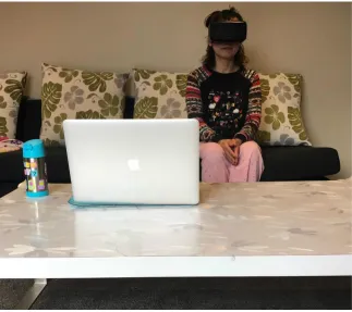
To reconstruct the physical environment near the user, the environmental depth-sensing
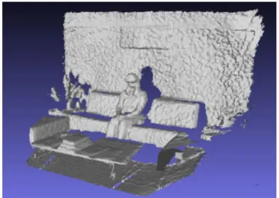
camera has been used. Figure 3.5 shows the colour and depth images captured using
the Microsoft Kinect depth-sensing camera facing the user wearing a HMD that was in
the prototype system setup from Chen’s [5] prototype.
Kinect SDK is used to run Kinect Fusion 3D reconstruction algorithm, which uses a
[image:37.596.120.512.158.437.2]stream of depth images to form a volumetric representation of the reconstructed surface.
Figure 3.6 shows the final mesh representation of the reconstructed physical environment
around the user.
Figure 3.6: KinectFusion 3D data captured from Kinect
However, after integrating the reconstruction module into a Unity project, the researcher
decided not to continue using Kinect Fusion because of the following reasons:
• The user had to stand and move the Kinect when reconstructing the surroundings,
which could not create a consistent experience when watching the movie.
• The speed of reconstructing, the quality of the image and the stability of
trans-forming reduced the efficiency of the proposed system.
• The design and modelling skills of 3D rendering were more complicated than
ex-pected which might slow down the progress of the project.
In this thesis, the Kinect is predominantly used to collect user’s skeleton tracking data,
while the SoftKinetic camera was principally utilized to render the real body data.
Therefore, the designed system is composed of two main depth sense cameras, the Kinect
Figure 3.7: Hardware setup sketch
According to previous related work, the Kinect presents a high performance in the user’s
skeletons tracking. Hence, the part of the body that has more tracking joints will be
prioritized in the augmented scenario.
The study focuses on immersive cinematic experience, which means the augmented
ob-jects should be related to the 360◦ movies. Therefore, the content-based objects created are required to be augmented on a real body. Existing 3D models could be acquired on
an open source website or database to match the video content.
3.3
Prototype System Setup Sketch
3.3.1 Hardware setup sketch
To show the improvement of visualization of the physical environment, a system
proto-type has been developed. The protoproto-type sketch aims to capture the whole environment
physical objects which would be augmented based on the theme of the movie in
real-time. In this system, users can see themselves and the physical objects in a more natural
way of blending into the cinematic scene.
The primary interfaces used in the immersive MR cinematic experience prototype
sys-tem contains a Kinect, an Oculus Rift DK2, and a SoftKinetic DepthSense 325. The
SoftKinetic camera will be mounted on the Oculus Rift DK2 while the Kinect will be
put on the other side. Figure 3.7 shows the sketch of how the devices are set up.
The Kinect is used to capture the broader view around the user, including the user
himself and his skeleton, as well as the surrounding physical environment. The depth
camera attached to the HMD will capture the physical objects from user’s perspective.
[image:39.596.116.521.329.576.2]3.3.2 System Architecture Design
Figure 3.8: System Architecture Design
The virtual environment is mostly implemented in the Unity 5 game engine. The Unity
5 game engine has a built-in feature supporting the Oculus Rift DK2 which eases the
software design. The SDK of the Softkinetic camera and the Microsoft Kinect need to
be installed and well explored.
Realistic or natural textures need to be created or found, and specific 360◦ movies need to be downloaded and imported into the Unity 5 game engine. Figure 3.8 shows the
3.4
User Experience Design
The user experience is the critical part of the prototype. There are several scenarios
which the researcher has considered.
The first one is providing several different types of 360◦ movies. These different movies will be augmented with different virtual objects. The advantage of this is that the user
will be more interested because of more abundant contents available. The disadvantage
is that it will be difficult to do the pair-comparison.
The second one is using the same 360◦ movies with different virtual objects augmented. Similar to the first scenario, it would be good for attracting the user’s attention, but
hard to conduct a pair-comparison.
The third one is using the same 360◦ movies with the same blended virtual objects. It may distract the user’s attention but will allow an easy pair-comparison.
Figure 3.9: Example for visual effects and adjustments [41]
There are different methods that can enhance the visualization as well. One is
adjust-ing the visual appearance of the video overlay, includadjust-ing hue, saturation, brightness
and transparency values of the corresponding pixels (Figure 3.9) [41]. Another one is
augmenting some virtual objects on top of the real objects, as shown in Figure 3.10 [24].
3.5
Summary
This chapter mainly outlined how the idea of this study had been generated, as well as
the initial design of the working system. The hardware setup , software structure and
user experience design have been described. In the next chapter, the implementation of
Prototype Implementation
This chapter explains the implementation of the prototype which the researcher used
in the study. Following the initial design consideration and the system sketches, the
working prototype was built which mainly consists of two parts, hardware, and software,
combining two depth cameras ( Kinect and SoftKinetic DepthSense 325), a HMD (Oculus
Rift DK2), and a headphone with 360◦ VR movies in Unity 3D environment.
4.1
System Architecture
Figure 4.1 presents the system architecture of the study prototype. This block diagram
demonstrates the comprehensive procedures and architecture of the working prototype.
There are four layers to the working prototype system, which are input, SDK and API,
integration and visualization, and output.
The system outlines four input source components. Oculus Rift DK2 Head sensor
pro-vides the head orientation, which helps the systems to define the skeleton position. With
the help of Kinect for Windows SDK v1.8 and the AM plugin script, the skeleton data
is transformed to the Unity 3D. Additionally, the SoftKinetic camera can deliver real
body image via its depth sensor SDK. 360◦ videos are passed into the Unity 3D as well.
It also describes the output AV source in Oculus Rift DK2 and the headphones following
the integration and visualization operations in Unity 3D.
Figure 4.1: System Architecture
4.2
The Hardware Requirements
The hardware requirements for this thesis is similar to prior work [5]. The Oculus Rift
HMD is used, on which is mounted a SoftKinetic RGBD camera with a 3D printed
frame. One more depth camera is needed to track skeleton information for this project,
which is the Microsoft Kinect. General hardware also contains a computer with the
game engine installed. A pair of proper headphones for sound effects of the movie is also
prepared.
4.2.1 Kinect
The Kinect sensor is designed as a black box which places on a small platform, ideal to
put down a desk. The specifications for the Kinect are shown in Table 4.1.
Essential native and managed tools and APIs are provided by the Kinect for Windows
SDK, which the user could develop Kinect-enabled applications for Microsoft Windows.
Table 4.1: Specifications for the Kinect [42]
4.2.2 SoftKinetic DepthSense Camera
SoftKinetic DepthSense 325 camera is the end-to-end provider of natural gesture
recog-nition solutions, delivered real-time 3D distance data for close interaction. It provides
depth data for software analysis from as close as 15cm, at up to 60fps. It contains a
DepthSense sensor, an high definition RGB sensor and two microphones.
Figure 4.2 shows the technical description of the SoftKinetic DepthSense 325 camera ,
while Figure 4.3 shows the product specifications [43].
Figure 4.3: SoftKinetic product specifications [43]
4.2.3 The Head-mounted Display
In the project, Oculus Rift Development Kit2 (DK2) is used as a HMD that allows
developers to build various games and experiences [44]. There are two components
[image:45.596.194.440.81.307.2]which have been used in this project, a headset for display and a sensor for tracking
(Figure 4.4).
(a) The headset (b)The sensor
Figure 4.4: Two components of Oculus Rift DK2 used in the study
The Oculus Rift DK2 has recommended computer specifications requirements to power
Table 4.2: Recommended Computer Specifications for Oculus Rift DK2 [45]
4.2.4 Personal Computer
These recommended specifications for the Oculus Rift DK2 also matches the system
requirements of Kinect and SoftKinetic camera. Therefore, the specifications of the
[image:46.596.105.513.364.730.2]computer used in this thesis project are shown below in Table 4.3.
Table 4.3: Computer specifications in this thesis project
4.2.5 The Hardware Setup
(a) Oculus Rift with SoftKinetic camera (b)Kinect with Oculus sensor
As described in previous subsections, the SoftKinetic camera would be mounted on the
Oculus Rift DK 2, and the Oculus sensor would sit on top of the Kinect. These are
shown in Figure 4.5.
4.3
The Software
The software in this study contained 4 parts. Unity 3D game engine, Kinect for Windows
SDK 1.8, Depthsense SDK, and SketchUp for 3D models.
4.3.1 Unity Game Engine
The virtual environment is mostly implemented in the Unity game engine. Unity is a
cross-platform game engine developing engaging 2D, 3D, VR, and AR apps and games.
It enables users to perform fast prototyping and deploy the content to virtually multiple
devices or media channels. It supports various platform. Therefore, it is convenient to
[image:47.596.158.475.386.682.2]connect Oculus Rift Dk2 to the Unity with built-in features [46].
Figure 4.6: Other setting interface in Unity 5
The Unity is frequently updated, the latest version being Unity 2017.3, while the Unity
version that was used for the project was version 5.4.6. This version was the most
Unity VR makes VR devices easily connected directly from Unity, without installing
any external plug-in in the projects. A primary Application Programming Interface
(API) and multiple devices’ compatibility of feature set are provided by Unity VR. It
also designs for the future devices and software. The user can gain many benefits from
native Unity VR support [47]. The native VR support feature can be activated by
changing the Unity application setting.
When the VR setting is enabled in Unity, it automatically renders a HMD and
head-track input, as well as understand the camera [47].
4.3.2 Kinect for Windows SDK 1.8
Kinect for Windows SDK 1.8 is an essential SDK to use if the Kinect-enabled applications
are developed in Microsoft Windows. It allocates both native and managed APIs and
[image:48.596.111.526.337.685.2]tools. Figure 4.7 shows the interface of Kinect for Windows developer toolkit v1.8.0.
Figure 4.7: Kinect for windows developer toolkit v1.8.0 Interface
To test the Skeleton tracking feature, a ”Skeleton Basic” sample has been selected. The
joints of the user are shown on the screen in Figure 4.8. It shows the user’s joints in three
20 joints data information of user’s skeleton tracking. These skeleton tracking data can
be transferred to Unity via amended AM plugin script, which will be elaborated in a
later section.
[image:49.596.110.524.395.660.2](a) Position 1 (b)Position 2 (c)Position 3
Figure 4.8: Showing user’s skeleton of Skeleton Basis Sample in Kinect for windows
SDK v1.8
4.3.3 SoftKinetic DepthSense SDK
Figure 4.9: DepthSense Viewer Interface
The SoftKinetic DepthSense 325 camera is used in the study, with the help of DepthSense
SDK, a user can access complete data from this camera, The viewer interface allows the
user to configure settings in colour node or depth node (Figure 4.9). The most relevant
would be rendered into the virtual environment. Figure 4.10 shows how the RGB colour
data, depth map, vertices map and the UV map are retrieved. To transfer compulsory
data streams into Unity 3D, a hand gesture plugin has been used, which will be described
in a later section.
(a) RGB colour data (b)Depth map (c) Vertices map (d) UV map
Figure 4.10: Camera data shown in Depth Sense Viewer
4.3.4 SketchUp
SketchUp1is a 3D modelling software. In SketchUp users can create 3D models, import
and export the 3D models and share them with others. The 3D warehouse contains a lot
of existing 3D models which are created by other users in the SketchUp. It is convenient
to find some established 3D models for the project and customize them into pieces.
Figure 4.11: SketchUp 3D warehouse search result interface
Figure 4.11 shows the search result interface in SketchUp 3D warehouse. In this study,
some 3D models of armors and weapons are imported to Unity which is explained in a
1
later section. Figure 4.12 shows the interface in SketchUp Make which can generate and
[image:51.596.150.484.123.328.2]edit the 3D models.
Figure 4.12: SketchUp 3D make interface
4.4
Prototype Integration
4.4.1 360◦ panoramic movie player in Unity 3D
The 360◦ movie can be downloaded from external resources, including broad themes. It is generated by a collection of cameras systems that can captured all 360◦ of a scene simultaneously.
Either a 360◦ camera or a collection of cameras with overlapping fields of view can be operated to capture whole spherical field images. The specialized software tools
are implemented to sew these captured images into a seamless panoramic video, which
renders a 360◦ projection. The commonly used projections are equirectangular and cubical.
To activate the internal video player support feature, a video player component attached
to a spherical GameObject needs to be generated. A “PanoramaVideoPlayerBehaviour”
script is implemented to call the video clip asset plugin, to import 360◦ movie into Unity 3D. Figure 4.13 shows the 360◦ movies player mapping.
Table 4.4 compares the advantages and disadvantages of the different video player assets
for Unity. Therefore, the video player asset the research used in the project is the “easy
(a) Equirectangular projections (b)Sphere generated in Unity 3D for mapping
(c)Video player with inside mapping on sphere (d) Main Camera’s perspective
[image:52.596.109.529.80.393.2]Figure 4.13: The procedures of mapping 360◦ panoramic movie in Unity 3D
Table 4.4: The comparison of different video player assets
Assets Advantages disadvantages
AVPro Trial Version Free Has watermarks
Easy Movie Texture Free Reduce video quality
AVPro Full version No watermark Expensive
4.4.2 AM Plugin, Skeleton in the Unity 3D
To import the skeleton tracking data from Kinect to Unity 3D, an updated AM Plugin
was generated based on the previous version used in previous work [5] [31]. A dynamic
link library (DLL) file was created and called by an AM Plugin Script in Unity 3D.
Natural User Interface (NUI) was as a reference provided by Microsoft, which listed
APIs for identifying the gesture as user input.
An AM plugin DLL file was generated to be called in Unity 3D via AM plugin script,
which made Unity 3D interfacing with Kinect motion tracking sensor. An index of
Table 4.5: Index of each joint defined in AM plugin script
Joint Index
HIP CENTER 0
SPINE 1
SHOULDER CENTER 2
HEAD 3
SHOULDER LEFT 4
ELBOW LEFT 5
WRIST LEFT 6
HAND LEFT 7
SHOULDER RIGHT 8
ELBOW RIGHT 9
WRIST RIGHT 10
HAND RIGHT 11
HIP LEFT 12
KNEE LEFT 13
ANKLE LEFT 14
FOOT LEFT 15
HIP RIGHT 16
KNEE RIGHT 17
ANKLE RIGHT 18
FOOT RIGHT 19
SKELETON COUNT 20
Each joint has its index, which helped to configure the skeleton based cylinders and
spheres in the Unity 3D.
The skeleton-based cylinders and spheres were created for every two joints in the Unity
3D environment. Therefore, these could be visualized by the user. Figure 4.14 shows
the left lower arm skeleton with cylinder and sphere in Unity 3D. In the Kinect Track
Skeleton Behaviour panel, the indexes were set from 5 to 6, which meant from elbow
left joint to wrist left joint, indicating that the skeleton would follow the movement of
the user’s left lower arm.
(a) Left low arm skeleton (b)Left low arm cylinder (c)Left low arm sphere
Figure 4.14: Left low arm skeleton with cylinder and sphere in Unity 3D
generated to track the user’s joints dynamically. This allows the virtual skeletons to be
moved and showed in the 360◦ panoramic movie.
(a) (b)
Figure 4.15: User’s skeleton shown in the 360◦ movie
4.4.3 3D Models augmented in Unity 3D
The previous section discussed the open source 3D Models in SketchUp. Figure 4.16
shows the completed 3D model of the armor.
This 3D armor consisted of significant components that did not match the skeletons set
in Unity 3D. Therefore, 3D models were broken down before implementation in Unity
3D. Fortunately, the SketchUp Make provides this feature; the breakdown components
of legs are shown in Figure 4.17. For instance, the initial 3D model only contained one
component of the two legs (4.17A). However, there were four joints for each leg, including
hip, knee, ankle, and foot. The researcher used an internal feature of the SketchUp to
break down one component into six components, as shown in 4.17B.
The cylinders and spheres of the skeletons were already generated in Unity 3D. The
components of the 3D model were implemented as being attached to the existing
Figure 4.16: 3D armor set in SketchUp
[image:55.596.108.529.75.335.2](a)The initial leg’s component of this armor (b) The leg’s components after breaking down
Figure 4.17: The components of armor’s legs
presents the one piece of left leg component attached to the cylinder and sphere skeleton
which combined left knee joint and left ankle joint.
The components were adjusted to match the required sizes and positions were aligned
with existing skeletons. The features in Unity 3D provides a good solution to achieve
calibrating, as shown in the process of calibrating the skeleton and armor’s component
in Figure 4.19.
3D models could be modified according to different themes and design requirements. The
3D models moved together with the skeleton based on user’s skeleton tracking (Figure
Figure 4.18: Left leg armor attached to left leg skeleton
(a) (b) (c)
Figure 4.19: Calibration of 3D armor’s leg component and skeleton in Unity 3D
4.5
Content
4.5.1 3D Models
Limited to the capability of creating sound 3D armors and weapons, existing and free
open source 3D models were chosen to be used in this project. The researcher initially
thought of light clothing, armors, weapons, and tattoos which would be easily linked to
the existing video content. After a comparison, as shown in Table 4.6, the researcher
chose to use the armor and weapon in this project.
Different sets of armor and weapons can be obtained in SketchUp a 3D warehouse.
Those models should be related to 360◦ movies. The armors are shown in Figure 4.21, while the weapons are shown in Figure 4.22.
Certainly, the Kinect skeleton tracking system has its limitations. After analyzing the
Figure 4.20: Left leg armor in running scene
Table 4.6: The comparison of different categories of 3D model
Categories Advantages Disadvantages
Light Clothes Colourful and attractive Difficult to simulate the fluttering
Armor Big enough to cover the skeleton Looks like VR feature
Weapon Easy to attract attention User may expect interactions with it
Tattoo Small, easy to stick to the body Too small to be noticed
(a) (b)
Figure 4.21: Different models of armor
At this stage, the researcher only has limited choices for 3D models and 360◦ videos. The choice of 360◦ videos were set to match the existing 3D models, so that the weapon and armor would be well-contained in the scene. The type of armor had led to the choice
(a) (b)
[image:58.596.112.528.75.346.2](c) (d)
Figure 4.22: Different models of weapon
4.5.2 360◦ movie for immersive experience
Following from the discussion of the 3D models used in the project, it was concluded that
the 360◦ movie used in this project should relate to armors and guns, which narrowed the search scope.
Initially, the researcher considered both realistic and animated background videos.
Be-cause armors and guns are widely used in animated games, a video “Red vs. Blue 360◦: Supply Drop” 2 was chosen. The user would quickly adapt to the surroundings when they found themselves in the gun game environment; more interactions are expected to
develop when all the surrounding characters are also wearing armor and are equipped
with guns, as shown in Figure 4.23.
Regarding the realistic video, it would be more challenging to find armor and gun
aug-mented content. Therefore, the study used on a timeless classic Star Wars themed video,
which was a video “Star Wars 360◦ VR Experience — Desert Assault” 3, as shown in Figure 4.24.
In further consideration during the working process, the researcher decided to conduct
the study with the realistic video only, which fitted the AV project better. It reduced
2
https://www.youtube.com/watch?v=1wLCbAdLZUs
Figure 4.23: Red vs. Blue 360◦: Supply Drop
Figure 4.24: Star Wars 360◦ VR Experience — Desert Assault
the AV effects in the animated video, which the users sometimes confused with the VR
effects.
4.5.3 Enhanced Visualization Prototype
An enhanced visualization working prototype was generated for user experience. The
video was trimmed to an appropriate two-minute length. To fit the Star Wars theme,
the characters in the scene were armed with Stormtrooper Armor in a desert.
Three different scenes had been created in Unity 3D, representing three different
visu-alizations. The first was the “ movie only” scene, which played the 360◦ movies only in the Unity, as shown in Figure 4.25A. The second was the “movie with real body” scene,
which blended the user’s real body in the scene. If the user moved their hands or legs
![Figure 2.2: Gyeongju VR theatre system integration [8]](https://thumb-us.123doks.com/thumbv2/123dok_us/9990166.499284/19.596.155.478.88.306/figure-gyeongju-vr-theatre-system-integration.webp)
![Figure 2.3: MR Interactive Theatre idea [9]](https://thumb-us.123doks.com/thumbv2/123dok_us/9990166.499284/20.596.149.482.78.308/figure-mr-interactive-theatre-idea.webp)
![Table 2.1: VR cinematic experience movies [11]](https://thumb-us.123doks.com/thumbv2/123dok_us/9990166.499284/21.596.173.455.165.370/table-vr-cinematic-experience-movies.webp)
![Figure 2.10: Joint Hierarchy [20]](https://thumb-us.123doks.com/thumbv2/123dok_us/9990166.499284/26.596.202.443.80.309/figure-joint-hierarchy.webp)
![Figure 2.11: The Kinect processes the index and thumb tip measurements [23]](https://thumb-us.123doks.com/thumbv2/123dok_us/9990166.499284/27.596.286.379.100.213/figure-kinect-processes-index-thumb-tip-measurements.webp)
![Figure 2.15: The overall structure of the Augmented Mirror system [21]](https://thumb-us.123doks.com/thumbv2/123dok_us/9990166.499284/31.596.140.499.90.361/figure-overall-structure-augmented-mirror.webp)
![Figure 2.17: The abstract design of the game engine [32]](https://thumb-us.123doks.com/thumbv2/123dok_us/9990166.499284/32.596.254.379.83.220/figure-abstract-design-game-engine.webp)