Nonlinear optical propagation in a tandem structure comprising nonlinear absorption
and scattering materials
Kangpeng Wang, Yongfeng Ju, Jin He, Long Zhang, Yu Chen, Werner J. Blau, and Jun Wang
Citation: Applied Physics Letters 104, 021110 (2014); doi: 10.1063/1.4862259
View online: http://dx.doi.org/10.1063/1.4862259
View Table of Contents: http://scitation.aip.org/content/aip/journal/apl/104/2?ver=pdfcov
Published by the AIP Publishing
Articles you may be interested in
Super-collimation by axisymmetric photonic crystals Appl. Phys. Lett. 104, 221108 (2014); 10.1063/1.4881839
Charge transfer assisted nonlinear optical and photoconductive properties of CdS-AgInS2 nanocrystals grown in semiconducting polymers
J. Appl. Phys. 113, 123107 (2013); 10.1063/1.4798383
Extreme optical nonlinearities in chalcogenide glass fibers embedded with metallic and semiconductor nanowires Appl. Phys. Lett. 99, 121102 (2011); 10.1063/1.3641423
Characterizing ultrashort optical pulses using second-order nonlinear nanoprobes Appl. Phys. Lett. 97, 261108 (2010); 10.1063/1.3532112
Octupolar versus dipolar crystalline structures for nonlinear optics: A dual crystal and propagative engineering approach
Nonlinear optical propagation in a tandem structure comprising nonlinear
absorption and scattering materials
Kangpeng Wang,1Yongfeng Ju,1Jin He,1Long Zhang,1,a)Yu Chen,2Werner J. Blau,1,3 and Jun Wang1,a)
1
Key Laboratory of Materials for High-Power Laser, Shanghai Institute of Optics and Fine Mechanics, Chinese Academy of Sciences, Shanghai 201800, China
2
Key Laboratory for Advanced Materials, Department of Chemistry, East China University of Science and Technology, 130 Meilong Road, Shanghai 200237, China
3
School of Physics and the Centre for Research on Adaptive Nanostructures and Nanodevices (CRANN), Trinity College Dublin, Dublin 2, Ireland
(Received 13 November 2013; accepted 24 December 2013; published online 15 January 2014)
Laser propagation in a tandem structure comprising carbon nanotubes and phthalocyanines is studied by Z-scan method. Due to the different mechanisms of the two materials, the laser beam can be attenuated with different absorptivities, by changing the sequence of light passing through each material. Numerical simulations considering the effect of path length and the change of nonlinear coefficient within each material are conducted for understanding the distribution of laser intensity in the tandem system and hence, fitting of the asymmetric Z-scan curves. The results are helpful for the design of nonlinear optical devices comprising multiple nonlinear materials and mechanisms.VC 2014 AIP Publishing LLC. [http://dx.doi.org/10.1063/1.4862259]
Study of light propagation in nonlinear optical (NLO) media is very helpful for the development of photonic devices, such as photonic crystals, optical switches, optical limiters, saturable absorbers, etc.1–5To date, numerous materials, such as phthalocyanines (Pcs),6–10 porphyrins,11,12 fullerene,13–16 carbon nanotubes,17–20 graphene,21,22 and their covalently/-non-covalently hybrids,22–28 etc., have been found to show strong nonlinear extinction (NLE) effect, viz. nonlinear absorption (NLA) and/or nonlinear scattering (NLS), to high intensity laser field and hence could be considered for practi-cal photonic materials and devices.29,30However, due to the restriction of its specific NLO mechanism, one material alone is not able to satisfy the full requirements of a viable device, i.e., working in a broad temporal and spectral range. For instance, nonlinear absorbers, e.g., metallophthalocyanines, fullerenes, two-photon absorption dyes, etc.,31 have a quick response time in the ps-fs regime, but covering only a relative narrow wavelength band (e.g.,420–650 nm for metalloph-thalocyanines7); NLS materials, e.g., nanotubes,17,18,20 gra-phene,21 Au nanoparticles, etc.,32,33 can work in a broad wavelength range from the visible to the near infrared, while generally responding at best in the ns regime.
In our previous works, we have studied the NLO response of single-walled carbon nanotube (SWNT) disper-sions, metallophthalocyanine solutions and their blends by using a ns pulse laser at 532 nm.7,17,20,34The phthalocyanine solutions exhibited strong reverse saturable absorption (RSA) at relatively lower intensities, while the effective NLE coefficientbeffdropped sharply as the increase of laser intensity due to the saturation effect of Pc molecules. In con-trast, the NLS effect of SWNT dispersions was weak at the lower laser intensities, but the beffwas improved with the increase of incident intensity which could be explained by a
bubble growth dynamics.35When blending nanotube and Pc together, the resulting composites enhanced the effective NLE coefficients in the higher intensity region when com-pared to the Pc solutions.34
To further understand the influence of coexistence of the NLS and NLA materials on the whole nonlinear response, we investigate and simulate, in this work, the nonlinear propaga-tion of laser in a cascade structure comprising the above-mentioned two materials with NLS and RSA mechanisms. For this purpose, a focused laser beam was allowed to pass through a tandem cuvette, in which the SWNT dispersions and tBu4PcZn (ZnPc) solutions were filled separately into the two compartments of the cuvette. Both the nanotube dispersions and ZnPc solutions were prepared in N, N-dimethylformamide (DMF) as the same procedure in our previous work.20,34 It should be mentioned that any sign of laser damage to the dis-persions and solutions was not find during the Z-scan measure-ments. The path length of each compartment was 2 mm, and the two compartments were isolated by a 1 mm fused silica. A standard open-aperture Z-scan system was used to measure the NLO response of the tandem device.36,37 This measures the total transmittance through the sample as a function of incident laser intensity, while the sample is gradually moved through the focus of a lens (along the z-axis). All experiments were per-formed using 6 ns pulses from a Q-switched Nd:YAG laser. The beam was spatially filtered to remove higher-order modes and tightly focused by a lens of 9 cm focal length. The laser was operated at the second harmonic, 532 nm, with a pulse rep-etition rate of 10 Hz. At the same time, a focusing lens setup was placed at 35 to the direction of the incident beam to monitor the scattered light from the cuvette. The acceptance angle of the convex lens was 3563.6.
Figures 1(a)–1(c) show a set of experimental Z-scan results, where the normalized transmission and the synchro-nal scattered sigsynchro-nal were plotted as functions of sample posi-tion Z. The z axis posiposi-tion was calibrated carefully to ensure
a)Authors to whom correspondence should be addressed. Electronic
addresses: [email protected] and [email protected]
the focus plane was coincided with the center of the tandem cuvette when Z¼0. In order to make sure that both of the two materials can contribute to the nonlinear extinction when the incident laser sequentially passes through the tan-dem structure, the concentrations of the SWNT and ZnPc were fixed at 0.033 g/l and 0.1 g/l, respectively. If the beam is incident into SWNT dispersions first and then ZnPc solutions, we refer this sequence to SWNT-ZnPc. Correspondingly, ZnPc-SWNT stands for the reversed sequence. It is clearly seen in Figs.1(a)–1(c) that the scat-tered signals, which are due to the nanotube dispersions, were always observed and increased gradually along with the focal intensity in either SWNT-ZnPc or ZnPc-SWNT configuration. The position of the scattering maximum was coincide with that of the nanotube compartment when it was moved to the focal point of the beam, i.e., Z1.5 mm for SWNT-ZnPc and Z 1.5 mm for ZnPc-SWNT. Due to the attenuation of ZnPc, the scattering intensity for ZnPc-SWNT was much weaker than that for SWNT-ZnPc. If the concen-tration of ZnPc was increased to 0.5 g/l, one could not see the obvious scattered signals any more in the ZnPc-SWNT configuration, implying that the nanotube dispersions had negligible influence on the whole nonlinear response, although the scattering was still significant in the SWNT-ZnPc configuration (See Figure S1).38
In general, the open-aperture Z-scan curves are symmet-ric about Z¼0, provided that the focused Gaussian beam field is symmetric and the thickness of nonlinear medium can be neglected.36,37 However, it can be seen that the Z-scan results in Figs.1(a)–1(c)are obviously asymmetric. For the ZnPc-SWNT curves, the valleys drift to Z 1.5 mm. Correspondingly, there is another inflection point on each ZnPc-SWNT curve at Z1.5 mm, which grows up to a
protrusion in Figs. 1(b) and 1(c). The situation of SWNT-ZnPc curves is similar but less pronounced. It should be pointed out that in either configuration, the valley on the left hand side corresponds to the focal plane located in the mid-dle of the right compartment of the tandem cuvette, while the right valley to the focal plane in the middle of the left compartment (as showed by the A and B points in Figs.1(c), 1(g), and1(h)). The asymmetry and infection points of the Z-scan curves are originated from the complex co-effect of both the difference of NLE responses of the NLS and RSA materials in the tandem system and the different laser inten-sities of each compartment in Gaussian shaped beam.
The intensity-dependent NLE coefficients, beff, can be calculated by using the open-aperture Z-scan theory.36,37 The normalized transmittance as a function of position z,
TNorm(z), is given byTNorm(z)¼Loge[1þq0(z)]/q0(z), where q0(z)¼q00/[1þ(z/z0)
2
], z0 is the diffraction length of the
beam. q00¼beffI0Leff.I0is the intensity of the light at focus. Leffis known as the effective length of the sample defined in
terms of the linear absorption coefficient, a0, and the path
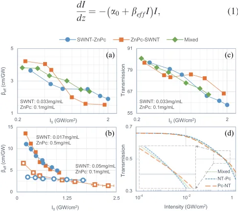
length of the sample, L, Leff¼[1-exp(a0L)]/a0. beff as a function of the on-focus intensity, I0, for the three configura-tions are given in Fig.2(a), where I0was deduced after deter-mining the beam waist by the Z-scan fitting. It is seen that the beffof ZnPc-SWNT is larger than that of SWNT-ZnPc when I0<0.6 GW/cm
2
, while the situation is reversed at the higher intensities. As the increasing of on-focus intensity I0, beff of the three configurations decrease with different slopes, i.e., ZnPc-SWNT>Mixture>SWNT-ZnPc. As shown in Fig. 2(b), the cross-overs of the beff-I0curves for ZnPc-SWNT and SWNT-ZnPc were also observed from the other tandem systems with different concentrations. Overall, the whole tandem structure exhibits a higherbeffbut decreas-ing very fast along with I0when the ZnPc concentration is enhanced. In contrast, for a higher SWNT concentration, the structure has a relative flat change ofbeffwith intensity.
The propagation equation in a NLE medium can be writ-ten in the form of36,37
dI
dz¼ a0þbef fI
I; (1)
FIG. 1. (a)–(c) Experimental results and (d)–(f) theoretical simulations of Z-scan measurements for the tandem structure at different intensities. (g) and (h) Illustrations of sample position along z corresponding to the A and B points in (c).
FIG. 2. (a) and (b)beffas a function of I0for the three configurations at dif-ferent nanotube and Pc concentrations. (c) Experimental results and (d) sim-ulations of transmission as a function of I0for the three configurations.
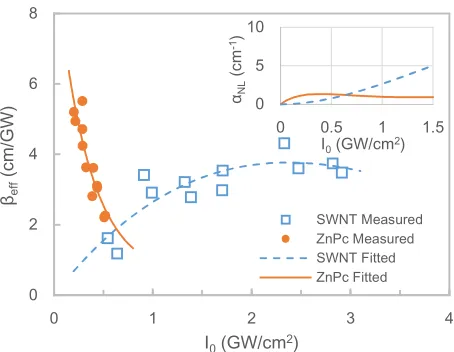
[image:3.612.56.295.54.317.2] [image:3.612.317.560.518.734.2]where I is the laser intensity, and z is the propagation dis-tance of light. In order to get the intensity dependentbefffor the nanotube dispersions and ZnPc solutions, a series of Z-scan measurements were performed at a range of inten-sities for each material alone. The path length was set to be 2 mm.beffof the two materials are plotted as a function of I0 in Fig.3. The concentrations of nanotubes and ZnPc were 0.033 g/l and 0.1 g/l, respectively. An exponential function and a 4-order polynomial were utilized to fit the ZnPc and nanotube data in Fig. 3, respectively. Based on the fitting results, we are able to obtain the nonlinear part of the whole extinction coefficient, i.e., aNL¼beffI0, which is illustrated in the inset of Fig.3. The aNL of ZnPc increases rapidly in the low intensity region but limiting in the higher intensities, while theaNLof nanotubes is increased monotonically in the experimental range. In experiments, the different nonlinear behavior of the two materials result in the diversity of Z-scan results for the different configurations.
Based on Eq. (1), the light propagation in the tandem configuration can be expressed as
dI1ðzÞ
dz ¼ ða01þb1ð ÞI1 I1ÞI1; 2 mmz0 mm (2.1)
dI2ðzÞ
dz ¼ ða02þb2ð ÞI2 I2ÞI2: 0 mmz2 mm (2.2)
The boundary conditions for Eqs. (2.1) and (2.2) are
I1ð2 mmÞ ¼Iin and I2ð0 mmÞ ¼I1ð0 mmÞ, respectively.
For numerical simulation, each compartment is considered as hundreds of ‘thin’ layers, inside which the laser beam is assumed to be parallel. In addition, the beam waist radius and laser intensity are recalculated when the beam passes through the surface of each ‘thin’ layer according to the focused Gaussian beam propagation function, in order to involve the effect of the change of beam waist. The b of nanotubes and ZnPc used in Eq.(2)for the simulations were quoted from the analytical fittings in Fig.3. For the Mixture configuration, we assume it is equivalent to a multi-compartment structure, comprising hundreds of ‘thin’ layers in a repetitive sequence of ZnPc-SWNT. Figure4illustrates the simulations of attenuation of intensity when a collimated
beam passing through the tandem cuvettes. Due to the different NLE behavior of nanotubes and ZnPc (see Fig.3), the decreas-ing trend of intensity is quite different in each compartment. Consistent with the experimental results in Fig. 2, the ZnPc-SWNT configuration shows stronger attenuation than the SWNT-ZnPc at a low level of incident intensity (0.1 GW/cm2), while the SWNT-ZnPc is the best for a higher intensity (0.9 GW/cm2). The nonlinear response of the Mixture is always in the middle of the two tandem configurations.
For numerical simulation of the Z-scan curves in Figs. 1(a)–1(c), the focused Gaussian beam propagation function in combination of Eq.(2)was employed. It can be seen that the trends of numerical evaluations are in very good agree-ment with the experiagree-ments, including the valley position and the feature of asymmetry. The distribution of laser intensity inside the tandem structure during a Z-scan measurement is shown in the inset of Fig.4(b). The white solid lines indicate the envelope of incident Gaussian beam, and the pseudo color corresponds to energy intensity. Moreover, the trans-mission as a function of intensity was simulated in Fig.2(d). Similar to the experimental results in Fig.2(c), there exists a cross-over point for the SWNT-ZnPc and ZnPc-SWNT sequences.
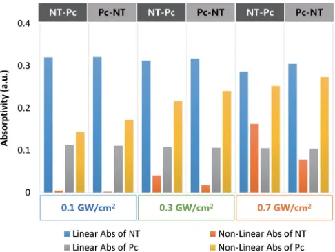
Referring to Eq.(1), the whole extinction coefficient a consists of a linear part a0 and a nonlinear part aNL, i.e., a¼a0þaNL. As mentioned above, a nonlinear medium can be treated theoretically as hundreds of ‘thin’ layers. The lin-ear and nonlinlin-ear energy absorptions in each ‘thin’ layer are calculated by considering a0 and aNL as constant in each layer. One can obtain the total linear/nonlinear energy absorption by summing up the linear/nonlinear energy absorptions of all layers. Then, the linear/nonlinear energy absorptivity of one compartment can be determined by divid-ing the linear/nonlinear absorption by the incident intensity at the front surface of the compartment. The relationship between the energy absorptivity of each compartment and that of the whole structure can be represented as Atol
¼ ðAL1þA
NL
1 Þ ðA
L
2þA
NL
2 Þ, where A
L
[image:4.612.317.558.544.742.2]and ANL stand for the linear and nonlinear absorptivity, respectively. Figure 5
[image:4.612.60.287.557.733.2]FIG. 3.beffas a function of I0for the nanotube dispersions and ZnPc solu-tions. Inset: The nonlinear part of the whole extinction coefficient as a func-tion of I0.
illustrates the linear and nonlinear part of laser energy absorp-tivity of nanotubes and PcZn under the different configura-tions. Compared with the significant fluctuation of the nonlinear absorptivity, the linear absorptivity remains rela-tively stable as the incident laser intensity increases. When the incident intensity reaches 0.3 GW/cm2, it can be seen that the NLE effect of nanotube dispersions is very weak, while ZnPc solutions exhibit strong NLA for both SWNT-ZnPc and ZnPc-SWNT configurations. That is to say, the nonlinear response of ZnPc dominates the absorptivity of the whole tan-dem system at the lower incident intensity. Thus, the ZnPc solutions exhibit the lower transmission at 0.3 GW/cm2when placed in front of the nanotube dispersions in ZnPc-SWNT, resulting in a higher absorptivity in comparison with SWNT-ZnPc. When the incident intensity is increased to 0.9 GW/cm2, the NLA of ZnPc solutions seems to be satu-rated and almost the same in both configurations. In this case, the NLS of nanotube dispersions dominates the absorptivity of the tandem device. Therefore, SWNT-ZnPc possesses higher absorptivity than ZnPc-SWNT.
Whereas the simulation results agree quite well with the experiments, it is worthy of discussing the origin of the sim-ulation errors to improve the simsim-ulation accuracy in future work. The major error comes from the calculation of the effective NLE coefficients,beffof ZnPc and nanotube disper-sions in Fig.3. The beff is obtained by the Z-scan theory, which requires to neglect the thickness of sample and con-sider thebeffas a constant in one scan. The approximate val-ues of beff in Fig. 3 results in errors to the simulation. Another error rises from the reflection of surfaces inside the tandem cuvettes. The multiple reflections of laser beam on the surfaces of the tandem cuvette would have influence on the estimation of real laser intensity in the NLO media, resulting in errors inbeffmeasurements and the deviation of absorptivity in simulation. The beam shape may also effect the simulation accuracy. However, our calculation indicates that the error brought by the top-hat approximation in the Z-scan simulation can be neglected, compared with the Gaussian approximation (See Figure S2).
In summary, the nonlinear light propagation in a tandem structure comprising both NLA and NLS materials was
studied by open aperture Z-scan and numerical simulation methods. By changing the lineal arrangement of ZnPc and SWNTs, a diversity of NLO responses and asymmetric Z-scan curves were observed in the tandem structure. A numer-ical model considering the different nonlinear mechanisms, as well as the thickness of the nonlinear media has been proved to be very effective to simulate the Z-scan results. The simulation is helpful to explain the asymmetry of Z-scan results, in which the effect of sample thickness and the change of NLE coefficient within a nonlinear material during one measurement cannot be neglected. This work may facili-tate the design of NLO devices comprising multiple nonlin-ear materials and mechanisms.
J.W. thanks the financial supports from the National 10000-Talent Program, CAS 100-Talent Program, the National Natural Science Foundation of China (NSFC, No. 61178007), and Science and Technology Commission of Shanghai Municipality (STCSM Nano Project, No. 11nm0502400 and Shanghai Pujiang Program 12PJ1409400). L.Z. thanks the financial supports from STCSM Excellent Academic Leader of Shanghai (No. 10XD1404600) and the Shanghai Natural Science Foundation (No. 11ZR1441500). Y.C. thanks NSFC (No. 61378072) and Joint project of Ministry of Education and State Administration of Foreign Experts Affairs (No. TS2010HDLG024). W.J.B. gratefully acknowledges a visit-ing professorship for international scientists from CAS, the China National High-end Foreign Experts Program (No. GDJ20130491010) and Science Foundation Ireland (SFI, 12/IA/1306).
1N. N. Lepeshkin, A. Schweinsberg, G. Piredda, R. S. Bennink, and R. W.
Boyd,Phys. Rev. Lett.93, 123902 (2004). 2
J. W. Perry, K. Mansour, I. -Y. S. Lee, X.-L. Wu, P. V. Bedworth, C.-T. Chen, D. Ng, S. R. Marder, P. Miles, T. Wada, M. Tian, and H. Sasabe, Science273, 1533–1536 (1996).
3M. Scalora, J. P. Dowling, C. M. Bowden, and M. J. Bloemer,Phys. Rev.
Lett.73, 1368–1371 (1994). 4
G. Xing, H. Guo, X. Zhang, T. C. Sum, and C. H. A. Huan,Opt. Express
18, 4564–4573 (2010).
5B. Macke and B. Segard,Phys. Rev. A
78, 013817 (2008). 6
R. Kumar, S. V. Rao, L. Giribabu, and D. N. Rao,Chem. Phys. Lett.447, 274–278 (2007).
7S. M. O’Flaherty, S. V. Hold, M. J. Cook, T. Torres, Y. Chen, M. Hanack,
and W. J. Blau,Adv. Mater.15, 19 (2003). 8
G. de la Torre, P. Vazquez, F. Agullo-Lopez, and T. Torres,Chem. Rev.
104, 3723–3750 (2004).
9G. De La Torre, P. Vazquez, F. Agullo-Lopez, and T. Torres,J. Mater.
Chem.8, 1671–1683 (1998). 10
J. S. Shirk, R. G. S. Pong, F. J. Bartoli, and A. W. Snow,Appl. Phys. Lett.
63, 1880–1882 (1993).
11H. Rath, J. Sankar, V. PrabhuRaja, T. K. Chandrashekar, A. Nag, and D.
Goswami,J. Am. Chem. Soc.127, 11608–11609 (2005). 12
M. O. Senge, M. Fazekas, E. G. Notaras, W. J. Blau, M. Zawadzka, O. B. Locos, and E. M. Ni Mhuircheartaigh,Adv. Mater.19, 2737–2774 (2007). 13F. Henari, J. Callaghan, H. Stiel, W. Blau, and D. Cardin,Chem. Phys.
Lett.199, 144–148 (1992). 14
G. Brusatin and R. Signorini,J. Mater. Chem.12, 1964–1977 (2002). 15
D. McLean, R. Sutherland, M. Brant, D. Brandelik, P. Fleitz, and T. Pottenger,Opt. Lett.18, 858–860 (1993).
16J. Callaghan, W. Blau, and F. Henari,J. Nonlinear Opt. Phys. Mater.
9, 505–521 (2000).
17
J. Wang, Y. Chen, and W. J. Blau, J. Mater. Chem. 19, 7425–7443 (2009).
18L. Vivien, P. Lancon, D. Riehl, F. Hache, and E. Anglaret,Carbon
[image:5.612.53.296.53.236.2]40, 1789–1797 (2002).
FIG. 5. The linear and nonlinear part of laser energy absorptivity of nano-tubes and PcZn under different configurations.
19L. Katz, A. Donval, E. Zussman, and Y. Cohen, ACS Appl. Mater.
Interface3, 4611–4618 (2011). 20
J. Wang and W. J. Blau,J. Phys. Chem. C112, 2298–2303 (2008). 21J. Wang, Y. Hernandez, M. Lotya, J. N. Coleman, and W. J. Blau,Adv.
Mater.21, 2430–2435 (2009). 22
M. B. M. Krishna, V. P. Kumar, N. Venkatramaiah, R. Venkatesan, and D. N. Rao,Appl. Phys. Lett.98, 081106 (2011).
23Z. B. Liu, J. G. Tian, Z. Guo, D. M. Ren, F. Du, J. Y. Zheng, and Y. S.
Chen,Adv. Mater.20, 511–515 (2008). 24
Y. Xu, Z. Liu, X. Zhang, Y. Wang, J. Tian, Y. Huang, Y. Ma, X. Zhang, and Y. Chen,Adv. Mater.21, 1275–1279 (2009).
25A. Sarkar, G. W. Rayfield, E. W. Taylor, S. Rahman, and S. Mirza,
J. Nanophotonics3, 031890 (2009). 26
B. Zhang, Y. Chen, J. Wang, W. J. Blau, X. D. Zhuang, and N. He, Carbon48, 1738–1742 (2010).
27S. M. O’Flaherty, J. J. Doyle, and W. J. Blau, J. Phys. Chem. B 108, 17313–17319 (2004).
28
Z.-B. Liu, Y.-F. Xu, X.-Y. Zhang, X.-L. Zhang, Y.-S. Chen, and J.-G. Tian,J. Phys. Chem. B113, 9681–9686 (2009).
29Y.-W. Song, S.-Y. Jang, W.-S. Han, and M.-K. Bae,Appl. Phys. Lett.
96, 051122 (2010).
30
H. Zhang, Q. Bao, D. Tang, L. Zhao, and K. Loh,Appl. Phys. Lett.95, 141103 (2009).
31G. S. He, G. C. Xu, P. N. Prasad, B. A. Reinhardt, J. C. Bhatt, and A. G.
Dillard,Opt. Lett.20, 435–437 (1995). 32
R. A. Ganeev, M. Suzuki, M. Baba, M. Ichihara, and H. Kuroda,J. Appl. Phys.103, 063102 (2008).
33
M. Anija, J. Thomas, N. Singh, A. S. Nair, R. T. Tom, T. Pradeep, and R. Philip,Chem. Phys. Lett.380, 223–229 (2003).
34
J. Wang and W. J. Blau,Chem. Phys. Lett.465, 265–271 (2008). 35I. M. Belousova, N. G. Mironova, and M. S. Yur’ev,Opt. Spectrosc.94,
86–91 (2003). 36
M. Sheik-Bahae, A. A. Said, and E. W. Van Stryland, Opt. Lett. 14, 955–957 (1989).
37M. Sheik-Bahae, A. A. Said, T.-H. Wei, D. J. Hagan, and E. W. Van
Stryland,IEEE J. Quantum Electron.26, 760–769 (1990). 38