Structured light techniques for 3D surface reconstruction
in robotic tasks
RODRIGUES, Marcos <http://orcid.org/0000-0002-6083-1303>, KORMANN,
Mariza, SCHUHLER, C and TOMEK, P
Available from Sheffield Hallam University Research Archive (SHURA) at:
http://shura.shu.ac.uk/7280/
This document is the author deposited version. You are advised to consult the
publisher's version if you wish to cite from it.
Published version
RODRIGUES, Marcos, KORMANN, Mariza, SCHUHLER, C and TOMEK, P (2013).
Structured light techniques for 3D surface reconstruction in robotic tasks. In:
KACPRZYK, J, (ed.) Advances in Intelligent Systems and Computing. Heidelberg,
Springer, 805-814.
Copyright and re-use policy
See
http://shura.shu.ac.uk/information.html
Sheffield Hallam University Research Archive
Structured Light Techniques for 3D
Surface Reconstruction in Robotic
Tasks
M.Rodrigues1
, M.Kormann1
, C.Schuhler2
, P.Tomek3
AbstractRobotic tasks such as navigation and path planning can be greatly enhanced by a vision system capable of providing depth perception from fast and accurate 3D surface reconstruction. Focused on robotic welding tasks we present a comparative analysis of a novel mathematical formulation for 3D surface reconstruction and discuss image processing requirements for reliable detection of patterns in the image. Models are presented for a parallel and angled configurations of light source and image sensor. It is shown that the parallel arrangement requires 35% fewer arithmetic operations to compute a point cloud in 3D being thus more appropriate for real-time applications. Experiments show that the technique is appropriate to scan a variety of surfaces and, in particular, the intended metallic parts for robotic welding tasks.
1 Introduction
One the main challenges in automated robotic tasks is the development of flexible systems that can be set up quickly and easily with minimum user intervention and can be switched over to another product line while main-taining quality and productivity. Small and medium enterprises normally find it difficult to invest in new technologies requiring expert knowledge and ex-tensive human training. Addressing those issues, the MARWIN Project [8] (Decision Making and Augmented Reality Support for Automatic Welding Installations) funded by the EU offers a solution to human-robot interaction by developing a cognitive welding robot where welding tasks and
parame-1
GMPR – Geometric Modelling and Pattern Recognition Group, Sheffield Hallam Univer-sity, UK,{m.rodrigues, m.kormann}@shu.ac.uk·2
TWI – The Welding Institute, Cam-bridge, UK, [email protected] · 3
MFKK – Invention and Research Center Services, Budapest, Hungary,[email protected]
ters are intuitively selected by the end-user directly from a library of CAD models. Robot trajectories are then automatically calculated from the CAD models and validated through fast 3D scanning of the welding scene. The role of the user is limited to high level specification of the welding task and to the confirmation or changing of welding parameters and sequences as suggested by MARWIN.
This paper focuses on describing optical techniques for fast 3D reconstruc-tion including image processing methods and a comparative analysis of sensor configurations concerning mathematical formulation and computational re-quirements. Optical methods for 3D surface reconstruction can be divided into two categories: passive methods that only require images from fairly uncontrolled illumination, and active methods that require controlled pat-terns of light to be projected onto the scene [10]. Passive methods include stereo vision, Shape-from-X (SfX) and Simultaneous Localization and Map-ping (SLAM). Active methods include Time-of-Flight (ToF) and Structured Light where surface patches are reconstructed from the geometric relation-ships existing between the source of light and sensor devices. Our research is focused on structured light techniques using coded and uncoded light pat-terns (e.g. [2, 15]). The main advantages of our techniques are speed and accuracy as a surface is scanned and reconstructed from a single 2D image in 40ms.
Structured light techniques can take many forms; a review of current tech-niques is provided in [11]. Salvi et al. [16] have proposed a classification
of structured patterns based on their coding strategy. For instance, we can identify recent techniques such as the Kinect Box based on projecting dot patterns [17], projection of a single pattern of uncoded stripes [13], coded stripes [15], colour patterns such as in [4], and alternating stripe patterns or phase shifting [18]. In general, structured light scanners in the literature assume an angled configuration in which the normals from the centre of the projector and the centre of the camera sensor meet at the calibration plane with a number of methods being proposed for reliable pattern detection (e.g. [1, 3, 5, 7, 12]).
2 The Geometry of Structured Light
[image:4.612.137.464.208.291.2]The principle of operation of the MARWIN structured light scanner is to project multiple planes of light onto the target surface whose image is recorded by a camera. The shape of the captured pattern is combined with the spatial relationship between the light source and the camera, to determine the 3D position of the surface along the pattern.
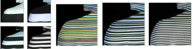
Fig. 1: Examples of coding schemes. From left to right: time-multiplexing, colour coding, variable width, and uncoded stripes.
The mapping from a captured image to a 3D surface requires knowledge of correspondences between captured patterns and projected elements. Many coding schemes have been proposed, a review is given in [16] and a few ex-amples are depicted in Figure 1. In order to avoid taking multiple shots as in time-multiplexing, several coding schemes can be used based on colour or variable width stripes. In this research we use grey-level stripes as in un-coded stripes of Figure 1 in which every stripe has the same width allowing a maximum resolution with a sufficiently dense pattern of stripes.
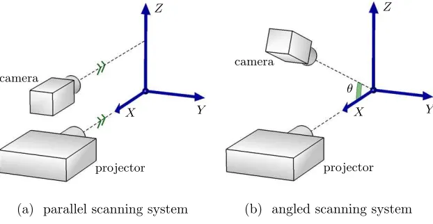
In order to proceed to the mathematical formulation, first it is necessary to define a coordinate system; all image and surface parameters will be related to this reference frame. We choose the coordinate system to be in relation to the light source as shown in Figure 2: the origin is set at a known distance from the centre of the projection. Concerning the physical arrangement, the camera and projector can be either in parallel or angled configuration as illustrated in Figure 3.
The problem we are trying to solve is defined as follows. Every pixel in the image as captured by the camera needs to be mapped into 3D to the chosen world coordinate system, also referred to as the system space. This is solved by determining to which light plane or stripe each pixel belongs to, and then through trigonometric relationships find the coordinates of the surface point imaged by the pixel.
projector X
Y Z
Dp
[image:5.612.136.464.108.242.2]horizontal sheet of light
Fig. 2: A coordinate system is defined in relation to the light source which also defines the indices of the light planes.
camera
projector
X Y
Z
(a) parallel scanning system
camera
projector
X Y
Z
θ
(b) angled scanning system
Fig. 3: Left, parallel configuration; right, standard angled configuration.
corresponding stripe index. From the point of view of the image sensor as illustrated in Figure 4, the mapping of a pixel to its coordinatespis defined as p=c+ (0,−hP F, vP F) [14]. Here cis the centre of the image,F is the focal length of the camera, P is the pixel size and each pixel in the sensor plane is a square of sizeP F ×P F.
[image:5.612.146.457.304.465.2]v
h
Fcamera
[image:6.612.188.410.100.212.2]←−
pFig. 4: The position of a pixel lying on a stripe of indexnin the image plane is transformed to coordinates (h, v) then to a pointp.
Fig. 5: Mapping of a surface pointqfrom (h, v, n) in camera space to (x, y, z) in system space. Left, side view of scanner; right: view from the top.
Ds: the distance between the camera and the projector Dp: the distance between the projector and the system origin
W: the width between successive light planes (or stripes) in the calibra-tion plane
P: the pixel size in the sensor plane of the camera
F: the camera focal distance
v, h: vertical and horizontal position of the pixel in camera space
x, y, z: 3D coordinates of a surface point
n: stripe index from the light source
θ, φ: angle between a light plane and its location in camera space
[image:6.612.138.458.267.375.2]x=Dp− DpDs vP Dp+Wn
(1)
y= hP DpDs
vP Dp+Wn
(2)
z= WnDs
vP Dp+Wn
(3)
The mathematical formulation for the angled configuration has originally been described in [13]. In this case, the mapping of a pixel (v, h) on stripe n
to its corresponding surface point (x, y, z) can be written as:
x= DcvP +W n(cosθ−vPsinθ)
vPcosθ+ sinθ+W n
Dp(cosθ−vPsinθ)
(4)
y=hP(Dc−xcosθ−zsinθ) (5)
z=W n(1−Dx p
) (6)
where the expressions for x in equation (4) can be substituted into equa-tion (6) forz, and then into equation (5) fory, so that each is formulated as a function ofv,handn.
The resolution in 3D space (in millimetres) for both parallel and angled configurations are mathematically equivalent: it depends on the spacing be-tween the projected planes, on the distance bebe-tween the surface and the light source and the dimension of the pixel space. The vertical resolution is affected by the spacing between the projected stripes which occupies several pixels in the image plane (the distance between two stripes). The horizontal resolution measured along each stripe is dependent on the horizontal dimension of the pixel space. We can formalize the resolution (δ) along the (x, y, z) dimensions by [14]:
δx= P D
2
pDs
[vP Dp+Wn][(v+ 1)P Dp+W n]
(7)
δy=P(Dp−x) (8)
δz= W
Dp
(Dp−x) (9)
In practice, it is possible to process one vertex in 3D per image pixel along each stripe (in the horizontal direction assuming that stripes are horizontal). To illustrate the magnitude of resolution, for an IDS camera with 1280×1024
It can be clearly seen from equations (1)–(6) that the mathematical formu-lation for the parallel configuration is simpler requiring less computing cycles than those of standard angled scanners: the parallel configuration requires 24 arithmetic operations per vertex in 3D against 37 operations for the angled (assuming that cosθ and sinθ are pre-computed). Thus, the parallel config-uration design is more appropriate for 3D real-time processing, as it requires 35% fewer operations than the angled configuration. In terms of mechanical construction and calibration, both designs are equivalent; the significant dif-ference is how the surface points (x, y, z) are calculated as described above from the known calibrated (i.e. measured) values of extrinsic parametersDs, Dp, W andθ.
3 Image Processing
[image:8.612.150.447.377.561.2]In order to reconstruct a surface in 3D according to the mathematical defi-nitions in the previous section, the following steps are necessary: (1) image noise filtering; (2) detect stripe patterns in the image; (3) index the stripes in relation to the centre of the system; then (4) map to 3D space. The mapping to 3D is accomplished using equations (1), (2), (3) for a parallel configuration and equations (4), (5), (6) for an angled configuration.
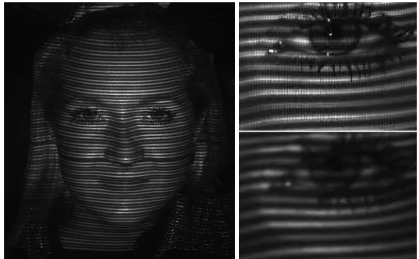
Fig. 6: Left, raw image; top right, raw detail; bottom right, filtered detail.
filter followed by a weighted mean filter. Details of raw and filtered image are shown on the right – although it may seem less sharp, each stripe on the bottom right has a smooth Gaussian profile making it easier to detect the peak of each stripe with sub-pixel accuracy, which is determined as the local maxima in the greyscale intensity values of each stripe. Once peaks or local maxima are detected, algorithms are run (e.g. [2, 13] based on maximum spanning tree and flood filling) to detect each stripe correctly indexing them, where the stripe with index 0 (zero) corresponds to the light plane emanating from the centre of the projector (the reference projected light plane). Stripes with ascending positive indices are above the centre stripe, negative below. With the correct indices determined, the mapping given by equations (1)–(3) or (4)–(6) are then applied resulting in a point cloud of vertices in 3D space.
4 Experimental Results
We developed a flexible design of a compact scanner prototype with internal adjustable mechanisms allowing it to be configured and calibrated either as a parallel or angled configuration. To this end, we must choose a calibration plane at an arbitrary distance from the light source (300mm was used in this paper, albeit the calibration plane can be set at any distance between 200–800mm or until stripes are still detectable in the image) and adjust the camera until the line perpendicular to the image sensor is either parallel to the light source or until it intercepts the system origin at the calibration plane as shown in Figure 3(b) for an angled configuration. Note that the calibra-tion plane does not set the maximum distance an object can be scanned. The limitation is due to the brightness of the projector and the reflective proper-ties of the surface being scanned which, ultimately, will determine whether or not stripe patterns can be detected. For instance, it is known that metal surfaces are difficult to scan due to high levels of specular noise, requiring special techniques and filters to be used.
The prototype depicted in Figure 7 uses an IDS UI-1241LE camera board [6] with image size 1280×1024 and a Microvision PicoP laser projector [9]
with resolution 848×480 pixels, equivalent to WVGA. The MARWIN project
Fig. 7: The compact GMPR Scanner assembly with laser projector and CMOS camera. DimensionW×H×L= 100×150×150mm.
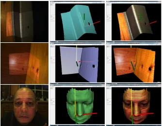
[image:10.612.134.468.324.583.2]Figure 8 depicts several reconstructed surfaces. As 3D reconstruction maps a 2D pixel to its counterpart 3D vertex, texture mapping is a straightforward process and there is no need for a post-processing texture mapping step as in standard scanners. Due to high specularity, metallic parts require two distinct image filtering functions namely a median followed by a weighted mean filter to make stripes detectable. In contrast, the other surfaces only require either a weighted mean filter or a mean filter. In terms of overall processing time we can break down in several steps: 40ms for 2D image filtering (median and mean filters), 40ms for calculation of a point cloud in space for the angled configuration (26ms for the parallel configuration), and 120ms for 3D mesh pos-processing (triangulation, small hole filling, mesh repairing and smoothing). With all the times computed, the current prototype in either parallel or angled configuration can operate in real-time at about 5 frames per second. If only the point cloud estimation is considered, the parallel configuration requires 35% fewer operations per vertex as compared to the angled one.
5 Conclusions
This paper describes research as part of the MARWIN project on 3D scan-ning of metallic components for robotic welding tasks. The focus is on the development of structured light scanners; a novel mathematical formulation for a parallel configuration is presented and compared to a standard angled arrangement of light source and image sensor. The built prototype consists of a camera board and a laser projector mounted on a mechanism designed for fine adjustments yielding either parallel or angled configurations. All in-terfaces to the control computer, camera boards and projector use standard USB connectors.
The main image processing requirement is identified as filtering images such that pixel intensities across stripes describe a smooth Gaussian pro-file for reliable detection of stripes peaks and throughs. Our experience has demonstrated that for reflective surfaces such as metals, employing a median filter followed by weighted mean filters can effective remove extremes of noise resulting in the required Gaussian profile of pixel intensities. On less reflective surfaces such as wood and skin tissue, a combination of mean and weighted mean filters proved effective.
surfaces is required; the focus of this paper has been on initial development and testing of the designs for parallel and angled configurations and on the ability to scan a variety of surfaces.
Acknowlegements
This work is supported by the European Commission, MARWIN Project Grant 286284 Research for SMEs SME-2011-1, from Nov 2011 to Oct 2013. We also acknowledge Willie Brink at Stellenbosh University (South Africa) for his work on geometry.
References
1. Albitar, C., Graebling, P., Doignon, C., 2007, “Robust structured light coding for 3D reconstruction”, in:Int Conf Comp Vis(ICCV), pp. 1–6.
2. Brink, W., A. Robinson, M. A. Rodrigues, “Indexing Uncoded Stripe Patterns in Structured Light Systems by Maximum Spanning Trees”,Proc BMVC British Ma-chine Vision Conference2008, ISBN 978-1-901725-36-0.
3. Chen, S., Li, Y., 2008, “Vision processing for realtime 3D data acquisition based on coded structured light”,IEEE T Image Process17, 167–176.
4. Clancy, N.T., Stoyanov, D., Groch, A., Maier-Hein, L., Yang, G.Z., Elson, D.S., 2011. “Spectrally-encoded fibre-based structured lighting probe for intraoperative 3D imag-ing”,Biomedical Optics Express 2, 3119–3128.
5. Gorthi, S., Rastogi, P., 2010, “Fringe projection techniques: Whither we are?”Opt Laser Eng 2, 133–140.
6. IDS Imaging GmbH, (2013) “USB2 uEye LE Camera Boards”, www.ids-imaging.com. Last accessed 9 Jan 2013.
7. Kawasaki, H., Furukawa, R., Sagawa, R., Yasushi, Y., 2008, “Dynamic scene shape reconstruction using a single structured light pattern”, in:IEEE Int Conf Comp Vis and Pat Rec(CVPR), pp. 1–8.
8. MARWIN: Decision making and augmented reality support for automatic welding installations, EU-funded Project no. 286284, Research for the Benefit of SMEs, from Nov 2011 to Oct 2013. http://www.marwin-welding.eu/
9. Microvision Inc, (2013). “MicroVision SHOWWX+ Laser Pico Projector”, microvi-sion.com. Last accessed on 9 Jan 2013.
10. Mirota, D.J., Ishii, M., Hager, G.D., 2011. “Vision-based navigation in image-guided interventions”,Annu Rev Biomed Eng 13, 297–319.
11. Mountney, P., Stoyanov, D., Yang, G.Z., 2010. “Three-dimensional tissue deformation recovery and tracking”,IEEE Signal Proc Mag 27, 14–24.
12. Pavlidis, G., Koutsoudis, A., Arnaoutoglou, F., Tsioukas, V., Chamzas, C., 2007, “Methods for 3D digitization of cultural heritage”, Journal of Cultural Heritage 8, 93–98.
13. Robinson, A., L. Alboul and M. Rodrigues, “Methods for Indexing Stripes in Uncoded Structured Light Scanning Systems”, Journal of WSCG, Vol.12, No.1-3, ISSN 1213– 6972.
15. Rodrigues, M. and A. Robinson, 2010, “Novel methods for real-time 3D facial recog-nition”, In: SARRAFZADEH, Majid and PETRATOS, Panagiotis, (eds.) Strategic Advantage of Computing Information Systems in Enterprise Management. Athens, Greece, ATINER, 169–180.
16. Salvi, J., J. Pag`es , J. Batlle, “Pattern codification strategies in structured light sys-tems”, Pattern Recognition Volume 37, Issue 4, April 2004, Pages 827–849.
17. Smisek, J. (2011). 3D with Kinect, IEEE International Conference on Computer Vision Workshops (ICCV Workshops), 6-13 Nov. 2011, 1154–1160.