Supervised Control of a Flying Performing Robot using its
Intrinsic Sound
PASSOW, Benjamin N., SMITH, Sophy, GONGORA, Mario A. and
HOPGOOD, Adrian A.
Available from Sheffield Hallam University Research Archive (SHURA) at:
http://shura.shu.ac.uk/5634/
This document is the author deposited version. You are advised to consult the
publisher's version if you wish to cite from it.
Published version
PASSOW, Benjamin N., SMITH, Sophy, GONGORA, Mario A. and HOPGOOD,
Adrian A. (2009). Supervised Control of a Flying Performing Robot using its Intrinsic
Sound. In: World congress on Computer Science and Information Engineering, 2009.
IEEE, 76-81.
Copyright and re-use policy
See
http://shura.shu.ac.uk/information.html
Supervised Control of a Flying Performing Robot using its Intrinsic Sound
Benjamin N. Passow and Sophy Smith
Institute of Creative Technologies
De Montfort University
LE1 9BH Leicester, United Kingdom
Mario A. Gongora and Adrian A. Hopgood
Centre for Computational Intelligence
De Montfort University
LE1 9BH Leicester, United Kingdom
Abstract
We present the current results of our ongoing research in achieving efficient control of a flying robot for a wide variety of possible applications. A lightweight small indoor heli-copter has been equipped with an embedded system and rel-atively simple sensors to achieve autonomous stable flight. The controllers have been tuned using genetic algorithms to further enhance flight stability. A number of additional sen-sors would need to be attached to the helicopter to enable it to sense more of its environment such as its current loca-tion or the localoca-tion of obstacles like the walls of the room it is flying in. The lightweight nature of the helicopter very much restricts the amount of sensors that can be attached to it. We propose utilising the intrinsic sound signatures of the helicopter to locate it and to extract features about its cur-rent state, using another supervising robot. The analysis of this information is then sent back to the helicopter using an uplink to enable the helicopter to further stabilise its flight and correct its position and flight path without the need for additional sensors.
1. Introduction
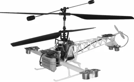
The interest on unmanned aerial vehicles (UAV) in-creased very much within the past decade [1]. UAV’s ca-pable of vertical take off and landing (VTOL) are versatile in manoeuvrability and thus can be applied in many indus-trial, military and civil applications. Our project goes even further as we are developing a multi-purpose lightweight autonomous flying robot that has the potential to be used for a variety of projects ranging from research in control to performing art. For this reason our autonomous helicopter is namedFlyper-flyingperformingrobot (Figure 1).
In this paper we present our ongoing research in achiev-ing stable control forFlyper. We applied two genetic algo-rithms (GA) to tune the existing controllers directly on the robot rather than evaluating individuals in simulation. In doing so, we confirmed that this method provided us with
more robust controllers [10]. Furthermore, we propose a novel method for localisation and enhancement of control that does not require additional sensors to be added to the lightweight indoor helicopter. This method is based on the helicopter’s intrinsic sound signature that is analysed by a supervising robot. The information extracted during the analysis is sent back to the helicopter enabling it to further stabilise and correct its position and flight path.
The remainder of this paper is structured as follows. tion 2 discusses some background and existing work. Sec-tion 3 presents the helicopter, its embedded system, and the GA tuned controllers. Section 4 introduces our sound based method to enhance flight stability. Conclusions are drawn in Section 5 and future work is suggested in Section 6.
2. Background
[image:2.595.314.540.549.688.2]The high manoeuvrability of helicopters makes them ideal for many applications. Unfortunately, the control of these highly unstable machines presents a difficult task. The high complexity of helicopter control and the big demand for UAVs in industry, military and the civil sector made this a highly active research topic. This section discusses recent work in the areas of helicopter control, controller tuning, and sound analysis.
2.1. Helicopter control
Much research is done on large helicopter platforms, with rotor radiuses up to 3.12 meters [9]. These have the ad-vantage of a much higher payload compared to lightweight helicopters, enabling them to carry a large number of sen-sors, computer systems, and batteries or fuel. But these have also many disadvantages. A large helicopter is more dangerous to humans in its proximity, much more expen-sive, experimental set-ups are more complex, tests more time consuming to run, and so on.
Traditional control techniques using a combination of proportional-integral-derivative (PID) control methods have been successfully used in helicopter control [16, 17, 13].
Puntunan and Parnichkun introduce a heading direc-tion and floating height controller for a single rotor heli-copter [13]. The control system uses a proportional plus derivative controller (PD) to maintain the helicopter’s head-ing and height, while a human pilot controls the horizontal movements remotely. Puntunan and Parnichkun present test results that confirm stable controlling capability with a rel-ative small margin of error.
Sanchezet al. present in [16] an unmanned helicopter control system combining a Mamdani type fuzzy logic con-troller with PID concon-trollers. The Fuzzy Inference System (FIS) controls the translational movement while the PID controllers handle the altitude and attitude of the helicopter. The system was tested via simulation for hovering and slow velocities which showed good performance.
Saripalli et al. introduce an autonomous helicopter which uses differential GPS, an inertial measurement unit (IMU), and a sonar sensor to determine the helicopter’s po-sition and attitude [17]. The control behaviours use PI con-trollers. Seven test flights confirm the successful control and landing of the helicopter. The work shows that PI con-trollers work well and the integral control parts are very use-ful in helicopter control.
2.2. Tuning controllers with GAs
Tuning and optimising controllers is an important and nontrivial task and a great deal of information is available on a variety of search and optimisation algorithms and tun-ing techniques for control algorithms [5, 4, 19].
Fleming and Purshouse present a survey about evolution-ary computing in control system engineering [5] and dis-cuss that only few real-time applications use EC methods for control. Additionally, it is mentioned that little work shows actual results rather than simulated results. A simu-lator of the corresponding system is very often used in or-der to evaluate the individuals fitness within a GA. Jakobiet al.[7] discuss the reality gap, evolving solutions in a sim-ulation and then applying these in the real world, and
re-search the effect of noise in a simulator to evolve control systems. A simulators limitations need to be identified so that it does not describe properties that do not exist in the real world or does not ignore properties that are essential in the real world [3].
In [19], Shimet al. present a comprehensive study of control design for an autonomous helicopter. Three dif-ferent control methodologies are compared and discussed: linear robust multi-variable control, nonlinear tracking con-trol, and fuzzy logic control with evolutionary tuning. A genetic algorithm is used to identify and tune the conse-quent parameters of four controllers using fitness evaluated in a simulation created from aerodynamics models. No per-formance tests have been conducted on a real system.
Phillipset al. introduce a fuzzy logic based flight con-troller for a UH-H1 Huey helicopter [12]. A GA is used to find the parameters of the fuzzy controllers, evaluating the individuals on a formal numerical model of the helicopter. The resulting controller is tested in simulation and on the actual helicopter. The tests on the real system showed os-cillations and a small problem in the design with the fuzzy logic controller where the simulation showed no problems.
In our work, we evaluated the individual solutions of the applied genetic algorithm on the actual system rather than on a simulation of it, thus avoiding the reality gap al-together [10].
2.3. Sound
To further enhance the helicopter’s stability and ex-tend its capabilities we propose a sound based supervised method. This method does not require additional sensors on the lightweight helicopter and uses a supervising robot to analyse the intrinsic sound signature of the helicopter.
Mammal binaural hearing is efficient and accurate and a fine example of biology’s intriguing evolutionary design. Nevertheless, it is very difficult to reproduce these capabil-ities on a robot using only two microphones. Fortunately robot audition is not limited to two microphones only and much research is being conducted on creating microphone arrays that make audition simpler, faster and more accurate. An array of eight microphones is used by Valinet al.[23] to accurately localise the direction to a sound source. Re-sults show that the set-up is capable of localising sound sources accurately within a few degrees. Detecting the distance to a sound source has not been tested but initial simulation showed less encouraging results. Kagamiet al.
Much research has been done on sound source locali-sation within the last decade [22]. Common and well un-derstood methods are time delay of arrival (TDOA), beam forming, MUSIC, Maximum likelihood method, and many more [14, 23, 6, 18, 20]. These methods show a good ac-curacy determining the direction of a sound source within a few degrees. For full localisation the distance to the sound source needs also to be determined. Other work showed distance estimation to unknown sound sources to be a chal-lenging task where only little accuracy is obtained [21, 23]. Analysing a sound can not only provide the location of the sound source but give information about its state. State and fault detection is an area of research concerning sound and vibration. Many people get their car checked when they start to hear an unfamiliar sound coming from it. The change of the typical sound of a machine is often an indi-cation of an incipient problem with it. In [15] Samuel and Pines, and in [11] Pawar and Ganguli present reviews on fault and state detection techniques for helicopters.
In [24], the state of a turbo pump is detected by analysing it’s sound signature. Westemeyeret al. first transform the sound signature into the frequency domain and then use two methods to identify the pumps state from the frequencies. The first technique used was a feedforward neural network where the inputs were the average of slots of frequencies. Clearly this method was not able to detect the shift in fre-quencies the pump is emitting when running up or down. The second method used a heuristic approach where the fre-quencies with the strongest signal are tracked over time to determine the state. This technique showed adequate accu-racy.
3. System Set-up
Flyper is based on a Twister Bell 47, an originally remote-controlled coaxial dual-rotor helicopter model. The autonomous helicopter has a rotor span of 340 mm, a weight of about 230 grams without battery, and can fly for about 10 minutes with its standard battery. Figure 1 showsFlyper
with its complete embedded system and the battery pack at-tached.
3.1. Flying Performing Robot
The control program runs on a microcontroller which reads three sonar sensors and a digital compass. A Blue-tooth module provides a communication link between the microcontroller and a host computer. The main purpose of this link is to stop the helicopter in case of an emergency but it also provides the host computer with flight teleme-try for performance analysis. The Bluetooth uplink to the helicopter is also used for the sound based control method introduced later in this paper.
The sonar sensors provide an effective means to deter-mine the helicopter’s altitude as well as attitude relative to the flat ground. Taking three distance measurements to the ground from three sides of the helicopter are enough to de-termine the helicopter’s attitude. With this system a pitch and roll angle of about 2◦ can be detected. Although the choice of sensors limits the use of the robot to rooms with a flat and obstacle free floor, the readings are accurate and ab-solute, thus easy to interpret. To widen the use of this robot platform, the sensors might be replaced in the future by an inertial measurement unit. The additional digital compass provides information about the helicopter’s heading.
The sensors give all the information needed to achieve stable flight except for drift. Moving air, as caused for ex-ample by air-conditioning, as well as very small errors in roll and pitch cause the helicopter to drift off. In order to solve this and other problems without adding a large num-ber of additional sensors, we propose a novel method based on sound.
3.2. Control architecture
The program running on the microcontroller reads all sensors and calculates the four actuator outputs using four separate PID controllers. Others showed that PID con-trollers are very capable of stabilising helicopters [2, 17, 13]. Nevertheless, determining good PID control parame-ters can be a challenging task [4].
We applied two GAs to tune the heading and altitude controllers of the helicopter. Rather than using a simulation of the system, we used the real helicopter itself to evalu-ate the fitness of the individuals in the GA. We have shown that the GA tuned heading controller evolved towards more robust solutions due to naturally occurring noise in the sys-tem [10]. Based on these results we have tuned the altitude controller in a similar way. The helicopter has been attached to a stand that allows the small helicopter to take off and fly in a height of up to 1.4 meters while being fixed in head-ing, roll, and pitch angles. The mass of the stand is kept as a minimum and the weight of the stand is neutralised with long springs. Every GA individual is evaluated by the controllers performance reaching and keeping at predefined setpoints. Although elitism has been applied, the best in-dividuals fitness does not increase monotonically. This is caused by the noise in the real system, giving a variable fit-ness for different instances of the same individual.
4. Enhancing control utilising sound
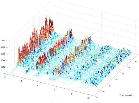
Figure 2. Helicopter sound spectrum over a complete test series.
location. One possible solution would be to add additional sensors to the helicopter to localise its position and gain fur-ther information about its state. The helicopter is designed for indoor use only and thus GPS cannot be used. A cam-era could be added to identify drift but this would require extensive computation and would not be able to identify an absolute position without the use of landmarks. Many other techniques could be used, such as multiple stereo vi-sion cameras or laser rangers, but these would dramatically increase the payload of the lightweight helicopter and the costs of the system. Rather than using additional sensors, we propose a system where a supervising robot analyses the helicopter’s intrinsic sound signature to localise the he-licopter and to identify its current state. The supervising robot will be using a microphone array such as suggested by Valinet al.[23] to record and analyse the sound in real time. The supervising robot sends the extracted informa-tion back to the helicopter to enable it to further stabilise its flight and to correct its position and flight path.
The helicopter’s intrinsic sound signature consists of a mixture of sounds produced by the rotor blades, the air pass-ing the helicopter body, motor noise and servo movement. The motors, rotor blades and the flybar generate a specific sound based on the power supplied to them and their cur-rent speed. The servos have a specific sound when chang-ing their lever position. These sounds can be heard by a supervising robot which analyses these to extract informa-tion about the helicopters locainforma-tion and state.
In an initial experimental set-up we recorded the he-licopter’s sound signature in various distances and states while being fixed to a slim stand. Figure 2 shows the com-plete spectrum of the helicopter up to 10 kHz in a distance of 3 meters. We increased the overall motor and rotor speed
Table 1. Helicopter loudness for different dis-tances
Distance Loudness Std.dev.
[meter] [arbitrary unit]
1 0.147 0.003
2 0.129 0.005
3 0.117 0.005
4 0.102 0.006
to 100% and commanded the helicopter to change head-ing, pitch, and roll rotational angles, performing each ma-noeuvre for approximately 5 seconds. The sound spectrum consists of the sounds generated by the helicopter includ-ing their harmonics. In the start-up phase while increasinclud-ing motor and rotor speed to 100% it can be observed that the helicopter’s overall loudness increases together with the fre-quencies of the emitted sounds.
The first and most important information we want to ob-tain is the location of the helicopter. The direction of the helicopter can be determined by the supervising robot using a sound localisation technique such as a frequency-domain beamformer [23]. Pinpointing the actual location of the he-licopter requires the direction as well as the distance to it. Determining the distance to a sound source without knowl-edge about its loudness is a challenging task [21, 23].
In another experiment we slowly increased motor and rotor speed from 0% to 100% while the helicopter was again fixed to a slim stand. Figure 3 shows the lower frequency spectrum of the helicopter sound signature recorded during the experiment.
The loudness of the helicopter is relative to the distance between helicopter and microphone as well as to the speed of its motors and rotors. Figure 3 shows that a change of motor and rotor speeds causes a shift in the observable fre-quency spectrum. Although the helicopter was commanded to increase motor and rotor speed gradually over the dura-tion of the experiment, the spectrum shows a slightly curved shift in frequency. This is to be expected as the helicopter’s power supply, a Lithium-Polymer battery pack, is not able to provide high amounts of power as easily as low amounts. The motor and rotor speed can be estimated by determining the frequency in the sound signature (Figure 3). By taking this estimate and the loudness of the helicopter, the distance to it can be determined, since its intrinsic noise is consistent and the level can be known. As expected, in an experimental set-up we were able to see the consistent difference in loud-ness of the helicopter for constant motor and rotor speed and different distances (Table 1).
[image:5.595.351.503.124.198.2]0 1 2 3 4 5 0
10 20 30 40 50 60 70 80 90 100
Frequency (kHz)
[image:6.595.310.544.76.262.2]Time [seconds]
Figure 3. Helicopter sound spectrum in tran-sition from 0% to 100% motor power.
technique based on our previous results. The system anal-yses only a part of the complete frequency spectrum be-tween 1200Hz and 2350Hz, which is split up into bands. Further, only frequency bands larger three times the mean of the spectrum are considered. This restricts the system to detect only major frequencies within the received sound signature. The centre of gravity of the remaining major fre-quency bands is used to determine the motor and rotor speed by multiplying it with a factor of 21.75. This factor has been determined by trial and error based on the fact that the sound signature’s frequency spectrum widens towards higher mo-tor and romo-tor speeds.
The system has been tested using an experimental setup where the helicopter slowly increased speed from 0% to 100% over 100 seconds, keeping at each percent increase for one second. In order to compare the results of the speed estimation with the known power input command we ap-plied a correcting factor. The speed estimate between 0 and 1 is taken to the power of 1.55 to best fit the nonlinear be-haviour of the battery. Figure 4 shows the test results where the x-axis is the command input in percent and time in sec-onds. The y-axis is the motor and rotor speed estimate con-verted to match the motor power command in percent.
Figure 4 shows some rather large errors for power com-mands less than 40%. The system detects the first harmon-ics of the actual frequencies of the motors and rotors. This is not a problem as the helicopter’s minimal power for fly-ing is never less than 50% thus the system will never detect these harmonics except for a short time before take-off and after landing. Table 2 presents the results from the test in numerical form. The mean error is the mean of the absolute of all errors of estimates bigger than 40%. For the standard
0 10 20 30 40 50 60 70 80 90 100 0
10 20 30 40 50 60 70 80 90 100
Time [seconds], Power output [%]
Estimated power [%]
Figure 4. Motor and rotor speed estimation test increasing speed from 0% to 100% over 100 seconds.
Table 2. Sound based motor and rotor power estimation test results
Mean Error StdDev Min Max
1.93% 1.94% 0.02% 6.64%
deviation of the error, the minimum error, as well as the maximum error only estimates larger than 40% are consid-ered.
5. Conclusions
This paper presents the current results of our ongoing re-search in achieving stable control of a small and lightweight indoor robotic-helicopter. We introducedFlyperand its em-bedded system and discussed the implemented control ar-chitecture and tuning strategy. Instead of adding more sen-sors to the lightweight robot we proposed a method com-bining a supervised and sound based method with existing controllers to further enhance stability and to enable the he-licopter to be localised in space.
[image:6.595.52.284.78.260.2]exist-ing helicopter controllers.
We showed that the motor and rotor speed as well as the power command can be estimated by analysing the fre-quency spectrum of the helicopter’s sound signature. We present a system capable of accurately determining the mo-tor and romo-tor speed and power command only by listening to the helicopter.
Further we propose the use of a sound localisation tech-nique to determine the direction to the helicopter. The per-ceived loudness of the helicopter is relative both to the dis-tance between helicopter and microphone and to the motor and rotor speeds. With our motor and rotor speed estimate the supervising robot can perform a robust analysis to corre-late the loudness of the helicopter to its distance. Using the angle and distance information we can determine the loca-tion of the helicopter in space in reference to the supervising robot.
6. Future work
We showed that our proposed system will enhance the helicopter’s stability and its abilities. As a next step we need to analyse the exact performance and capability gain. For this reason we will build a microphone array and implement the system on a supervising robot that analyses the data in real time and sends it to the helicopter. We will then conduct further experiments to analyse the stability and flightpath of the helicopter with and without the supervised robot.
Additionally we will focus further on feature extraction from the sound signature to enable the supervising robot to extract more information about the helicopter’s current states. With this additional information we will further en-hanceFlyper’s capabilities and flight stability.
Acknowledgment
The authors would like to thank Prof. Andrew Hugill, Director of the Institute of Creative Technologies, De Mont-fort University, for supporting this research project.
References
[1] S. Bouabdallah, M. Becker, and R. Siegwart. Autonomous miniature flying robots: coming soon!-research,
develop-ment, and results.Robotics & Automation Magazine, IEEE,
14(3):88–98, 2007.
[2] S. Bouabdallah, R. Siegwart, and G. Caprari. Design and
control of an indoor coaxial helicopter. 2006 IEEE/RSJ
In-ternational Conference on Intelligent Robots and Systems, pages 2930–2935, 2006.
[3] R. A. Brooks. Intelligence without reason. In J. Myopoulos
and R. Reiter, editors,Proceedings of the 12th International
Joint Conference on Artificial Intelligence, pages 569–595,
Sydney, Australia, 1991. Morgan Kaufmann publishers Inc.: San Mateo, CA, USA.
[4] P. De Moura Oliveira. Modern heuristics review for pid
con-trol systems optimization: A teaching experiment. In
Pro-ceedings of the 5th International Conference on Control and Automation, ICCA’05, pages 828–833, 2005.
[5] P. Fleming and R. Purshouse. Evolutionary algorithms in
control systems engineering: a survey.Control Engineering
Practice, 10(11):1223–1241, 2002.
[6] J. Huang, N. Ohnishi, and N. Sugie. Building ears for robots:
sound localizationand separation. Artif. Life Robotics,
1(4):157–163, 1997.
[7] N. Jacobi, P. Husbands, and I. Harvey. Lecture Notes
in Computer Science - Advances in Artificial Life, chapter Noise and the Reality Gap: The Use of Simulation in Evo-lutionary Robotics, pages 704–720. Springer, UK, 1995. [8] S. Kagami, H. Mizoguchi, Y. Tamai, and T. Kanade.
Mi-crophone array for 2d sound localization and capture. In Robotics and Automation, 2004. Proceedings. ICRA’04. 2004 IEEE International Conference on, volume 1, 2004. [9] B. Ludington, E. Johnson, and G. Vachtsevanos.
Augment-ing uav autonomy.Robotics & Automation Magazine, IEEE,
13(3):63–71, 2006.
[10] B. N. Passow, M. A. Gongora, S. Coupland, and A. A. Hop-good. Real-time evolution of an embedded controller for an
autonomous helicopter. InProceedings of the IEEE
Inter-national Congress on Evolutionary Computation (CEC’08), Hong Kong, 2008.
[11] P. Pawar and R. Ganguli. Helicopter rotor health
monitoring-a review. InProceedings of the Institution of Mechanical
En-gineers, Part G: Journal of Aerospace Engineering, volume 221, pages 631–647. Professional Engineering Publishing, 2007.
[12] C. Phillips, C. L. Karr, and G. Walker. Helicopter flight
con-trol with fuzzy logic and genetic algorithms. Engineering
Applications of Artificial Intelligence, 9(2):175–184, 1996.
[13] S. Puntunan and M. Parnichkun. Control of heading
di-rection and floating height of a flying robot. InIEEE
In-ternational Conference on Industrial Technology, volume 2, pages 690–693, Bangkok, Thailand, 2002.
[14] G. Reid and E. Milios. Active stereo sound localization. The Journal of the Acoustical Society of America, 113:185, 2003.
[15] P. Samuel and D. Pines. A review of vibration-based
tech-niques for helicopter transmission diagnostics. Journal of
Sound and Vibration, 282(1-2):475–508, 2005.
[16] E. Sanchez, H. Becerra, and C. Velez. Combining fuzzy and
pid control for an unmanned helicopter. InAnnual Meeting
of the North American Fuzzy Information Processing
Soci-ety, pages 235–240, Unidad Guadalajara, Mexico, 2005.
[17] S. Saripalli, J. Montgomery, and G. Sukhatme.
Vision-based autonomous landing of an unmanned aerial vehicle. InRobotics and Automation, 2002. Proceedings. ICRA’02. IEEE International Conference on, volume 3, pages 2799– 2804, Washington, DC, May 2002.
[18] R. Schmidt. Multiple emitter location and signal parameter
estimation. InIEEE Transactions on Antennas and
[19] H. Shim, T. Koo, F. Hoffmann, and S. Sastry. A comprehen-sive study of control design for an autonomous helicopter. In Decision and Control, 1998. Proceedings of the 37th IEEE Conference on, volume 4, pages 3653–3658, Tampa, Florida, USA, December 1998.
[20] P. Stoica and K. Sharman. Maximum likelihood methods
for direction-of-arrival estimation. InIEEE Transactions on
Acoustics, Speech, and Signal Processing, volume 38, pages 1132–1143, 1990.
[21] Y. Tamai, Y. Sasaki, S. Kagami, and H. Mizoguchi. Three ring microphone array for 3d sound localization and
sepa-ration for mobile robot audition. InIntelligent Robots and
Systems, 2005.(IROS 2005). 2005 IEEE/RSJ International Conference on, pages 4172–4177, 2005.
[22] J. Valin. Auditory System for a Mobile Robot. PhD thesis,
Ph. D., Faculte de genie, University of Sherbrooke, Sher-brooke, Canada, 2005.
[23] J. Valin, F. Michaud, and J. Rouat. Robust localization and tracking of simultaneous moving sound sources using
beam-forming and particle filtering. Robotics and Autonomous
Systems, 55(3):216–228, 2007.
[24] S. Westemeyer, L. Wagner, L. Nolle, A. Hopgood, F. Biegler-Koenig, and N. Braithwaite. A heuristic algo-rithm for detecting the state of a turbo molecular pump from
its sound. In8th International MENDEL Conference on Soft